Sign In
Upload
Manuals
Brands
Rockwell Automation Manuals
Servo Drives
Allen-Bradley Kinetix 6000
Rockwell Automation Allen-Bradley Kinetix 6000 Manuals
Manuals and User Guides for Rockwell Automation Allen-Bradley Kinetix 6000. We have
4
Rockwell Automation Allen-Bradley Kinetix 6000 manuals available for free PDF download: User Manual, Selection Manual, Reference Manual
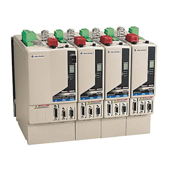
Rockwell Automation Allen-Bradley Kinetix 6000 User Manual (268 pages)
Multi-axis Servo Drive
Brand:
Rockwell Automation
| Category:
Servo Drives
| Size: 11.6 MB
Table of Contents
Table of Contents
3
About this Publication
9
Conventions Used in this Manual
9
Preface
9
Who Should Use this Manual
9
Additional Resources
10
Chapter 1
11
Introduction
11
Start
11
About the Kinetix 6000 Drive System
12
Appendix D
15
Agency Compliance
16
CE Requirements (System Without LIM)
17
CE Requirements (System with LIM)
17
Catalog Number Explanation
16
Chapter 2
19
Introduction
19
Planning the Kinetix 6000 Drive System Installation
19
System Design Guidelines
20
System Mounting Requirements
20
Transformer Selection
21
Circuit Breaker/Fuse Selection
22
Enclosure Selection
23
Minimum Clearance Requirements
26
Minimizing Electrical Noise
27
Bonding Modules
27
Bonding Multiple Subpanels
29
Establishing Noise Zones
30
Cable Categories for Kinetix 6000 Systems
37
Noise Reduction Guidelines for Drive Accessories
39
Chapter 3 Introduction
43
Using 2094 Mounting Brackets
43
Installing the 2094 Power Rail
44
Mounting the Kinetix 6000 Drive System
43
Determining Mounting Order
44
Mounting the Modules
45
Mounting the External Shunt Module
48
Chapter 4
49
Introduction
49
Kinetix 6000 Connector Data
49
Locating IAM/AM Connectors and Indicators
50
Safe-Off Connector Pinout
52
I/O Connector Pinout
54
Motor Feedback Connector Pinouts
55
Auxiliary Feedback Connector Pinouts
57
IAM Input Connector Pinouts
58
IAM and am Motor Power and Brake Connector Pinouts
59
Understanding IAM/AM Signal Specifications
60
Digital Inputs
60
Publication 2094-UM001A-EN-P — September
60
SERCOS Connections
61
Analog Outputs
62
Contactor Enable Relay
63
Motor/Resistive Brake Relay
64
Control Power Input
65
Understanding Feedback Specifications
66
Motor and Auxiliary Feedback Specifications
66
Feedback Power Supply
67
Locating Shunt Module Connectors and Indicators
68
Chapter 5
69
Connecting the Kinetix 6000 Drive System
69
Introduction
69
Understanding Basic Wiring Requirements
69
Building Your Own Cables
70
Routing Power and Signal Wiring
70
Determining Your Type of Input Power
71
Grounded Power Configurations
71
Ungrounded Power Configurations
73
DC Common Bus Configurations
74
Common Bus Fusing Requirements
75
Setting the Ground Jumper in Ungrounded Power Configurations
75
Setting the Ground Jumper
76
Grounding Your Kinetix 6000 System
78
Grounding Your System to the Subpanel
78
Grounding Multiple Subpanels
79
Power Wiring Requirements
80
Wiring Guidelines
83
Wiring the LIM Connectors
84
Wiring the Auxiliary Input Power (APL) Connector
84
Wiring the VAC LINE (IPL) Connector
85
Wiring the VAC LOAD (OPL) Connector
86
Wiring the Control Power Output (CPL) Connector
87
Wiring the Auxiliary Power Output (P2L) Connector
88
Wiring the Brake Power Output (24V DC) Connector
89
Wiring the IAM/AM Connectors
90
Wiring the Control Power (CPD) Connector
90
Wiring the Input Power (IPD) Connector
91
Wiring the Contactor Enable (CED) Connector
93
Wiring the Safe-Off (SO) Connector
94
Wiring the Motor Power (MP) Connector
95
Wiring the Motor/Resistive Brake (BC) Connector
101
Applying the Motor Cable Shield Clamp
103
Understanding Feedback and I/O Cable Connections
104
Flying-Lead Feedback Cable Pin-Outs
105
Publication 2094-UM001A-EN-P — September
106
Wiring Feedback and I/O Connectors
108
Connecting Premolded Motor Feedback Cables
108
Wiring Panel-Mounted Breakout Board Kits
109
Wiring Low-Profile Connector Kits
110
Understanding External Shunt Module Connections
113
Understanding Resistive Brake Module Connections
114
Connecting Your SERCOS Fiber-Optic Cables
115
Chapter 6
119
Configure and Startup the Kinetix 6000 Drive System
119
Introduction
119
Configure the IAM/AM
120
Configure the Logix SERCOS Interface Module
125
Configure the Logix Controller
125
Configure the Logix Module
126
Configure the Kinetix 6000 Modules
128
Appendix D
131
Configure the Motion Group
132
Configure Axis Properties
133
Download the Program
134
Apply Power to the Kinetix 6000 Drive
135
Test and Tune the Axes
138
Test the Axes
138
Tune the Axes
141
Chapter 7
145
Introduction
145
Safety Precautions
145
Troubleshooting the Kinetix 6000 Drive System
145
Interpreting Status Indicators
146
Error Codes
146
IAM/AM Status Indicators
152
SM Status Indicators
153
Troubleshooting General System Problems
155
Understanding Logix/Drive Fault Behavior
157
Supplemental Troubleshooting Information
160
Tools for Changing Parameters
160
Using Analog Test Points to Monitor System Variables
161
Before You Begin
163
Chapter 8
163
Introduction
163
Removing and Replacing the Kinetix 6000 Drive Modules
163
Removing Power Rail Modules
164
Replacing Power Rail Modules
165
Removing the Power Rail
166
Replacing the Power Rail
167
Publication 2094-UM001A-EN-P — September
168
Introduction
169
Appendix A Power Specifications
170
Integrated Axis Module (Converter) Power Specifications
170
Axis Module (Inverter) Power Specifications
172
Shunt Module Power Specifications
173
Circuit Breaker/Fuse Specifications
177
Contactor Ratings
179
Transformer Specifications for Control Power Input
179
Power Dissipation Specifications
180
General Specifications
181
Maximum Feedback Cable Lengths
181
Environmental Specifications
181
Weight Specifications
182
Certifications
182
AC Line Filter Specifications
183
External Shunt Module Specifications
184
Product Dimensions
185
Appendix B
191
Interconnect Diagrams
191
Introduction
191
Wiring Examples
192
Power Wiring Examples
193
DC Common Bus Wiring Examples
197
Shunt Module Wiring Examples
201
Axis Module/Motor Wiring Examples
204
Controlling a Brake Example
210
System Block Diagrams
212
Appendix C
215
Introduction
215
Upgrading Firmware
215
Using Controlflash Software to Upgrade Drive Firmware
216
Before You Begin
216
Selecting the Drive to Upgrade
217
Configuring Logix Communications
218
Flashing Firmware
220
Troubleshooting Controlflash
222
Verifying the Firmware Upgrade
223
Using Driveexplorer Software to Upgrade Drive Firmware
224
Before You Begin
224
Selecting Axis Modules to Upgrade
224
Hyperterminal Configuration
226
Flashing Firmware
228
Publication 2094-UM001A-EN-P — September
229
Before You Begin
231
Introduction
231
Calculating Additional Bus Capacitance
232
Calculating Total Bus Capacitance
232
Kinetix 6000 Capacitance Values
233
Common Bus Capacitance Example
234
Setting the Additional Bus Capacitance Parameter
235
Removing SERCOS Communication
235
Setting the Additional Bus Capacitance Parameter
236
Saving the Add Bus Cap Parameter to Non-Volatile Memory
237
Reconnecting SERCOS Communication
238
Appendix E
239
Before You Begin
239
Integrating Resistive Brake Modules with Kinetix 6000 Drives
239
Introduction
239
Understanding Safety Precautions
240
Safety Standards for Reference
240
Background on Safety Design
241
Stop Categories
241
Risk Assessment
242
Control Reliability
243
Resistive Brake Module Wiring Examples
243
Setting the RBM Delay Time Using Driveexplorer
252
Removing SERCOS Communication
252
Setting the RBM Delay Time Parameter
253
Saving the Delay Time Parameter to Non-Volatile Memory
254
Reconnecting SERCOS Communication
255
Publication 2094-UM001A-EN-P — September
256
Advertisement
Rockwell Automation Allen-Bradley Kinetix 6000 User Manual (280 pages)
Multi-axis Servo Drives
Brand:
Rockwell Automation
| Category:
Servo Drives
| Size: 12.11 MB
Table of Contents
Table of Contents
5
About this Publication
11
Conventions Used in this Manual
11
Who Should Use this Manual
11
Additional Resources
12
Chapter 1 Introduction
13
IAM/AM Module Series Change
13
About the Kinetix 6000 Drive Systems
14
Typical Hardware Configurations
15
Typical Communication Configurations
18
Catalog Number Explanation
19
Drive Component Compatibility
20
Agency Compliance
21
CE Requirements (System Without LIM Module)
21
CE Requirements (System with LIM Module)
22
Introduction
23
Chapter 2 System Design Guidelines
24
System Mounting Requirements
24
Transformer Selection
25
Circuit Breaker/Fuse Selection
26
Enclosure Selection
27
Minimum Clearance Requirements
30
Electrical Noise Reduction
31
Bonding Modules
31
Bonding Multiple Subpanels
33
Establishing Noise Zones
34
Cable Categories for Kinetix 6000 Systems
41
Noise Reduction Guidelines for Drive Accessories
43
Introduction
47
Chapter 3
47
Using the 2094 Mounting Brackets
47
Installing the 2094 Power Rail
48
Determine Mounting Order
48
Mount Modules on the Power Rail
49
Introduction
53
Chapter 4 IAM/AM Module Features
54
Safe-Off Connector Pinout
56
I/O Connector Pinout
57
Motor Feedback Connector Pinout
58
Auxiliary Feedback Connector Pinout
60
IAM Input Connector Pinout
61
IAM and am Motor Power and Brake Connector Pinout
62
Control Signal Specifications
63
Digital Inputs
63
SERCOS Communication Specifications
64
Analog Outputs
65
Contactor Enable Relay
66
Power and Relay Specifications
67
Motor/Resistive Brake Relay
67
Input Power Cycle Capability
68
Peak Enhancement Specifications
69
Control Power
72
Feedback Specifications
73
Absolute Position Feature
73
Feedback Power Supply Specifications
75
Auxiliary Position Feedback Encoders
76
Chapter 5
77
Introduction
77
Basic Wiring Requirements
77
Building Your Own Cables
78
Routing the Power and Signal Cables
78
Determine the Input Power Configuration
79
Grounded Power Configurations
79
Ungrounded Power Configurations
81
DC Common Bus Configurations
82
Common Bus Fusing Requirements
83
Setting the Ground Jumper in Ungrounded Power Configurations
83
Set the Ground Jumper
84
Grounding the Kinetix 6000 Drive System
89
Ground the Power Rail to the System Subpanel
89
Ground Multiple Subpanels
90
Power Wiring Requirements
91
Power Wiring Guidelines
93
Wiring the IAM/AM Module Connectors
94
Wire the Control Power (CPD) Connector
94
Wire the Input Power (IPD) Connector
95
Wire the Contactor Enable (CED) Connector
97
Wiring the Safe-Off (SO) Connector
98
Wire the Motor Power (MP) Connector
99
Wire the Motor/Resistive Brake (BC) Connector
106
Apply the Motor Cable Shield Clamp
109
Feedback and I/O Cable Connections
110
Flying-Lead Feedback Cable Pin-Outs
112
Wiring the Feedback and I/O Connectors
115
Connect Premolded Motor Feedback Cables
115
Connect Panel-Mounted Breakout Board Kits
116
Wire Low-Profile Connector Kits
117
External Shunt Module Connections
120
RBM Module Connections
121
SERCOS Fiber-Optic Cable Connections
122
Installing the Fiber-Optic Connector Bracket Kit
125
Connecting the Kinetix 6000 Drive System
77
Chapter 6
127
Introduction
127
Configure the Drive Modules
128
Configure the Logix SERCOS Interface Module
133
Configure the Logix Controller
133
Configure the Logix Module
135
Configure the Kinetix 6000 Drive Modules
137
Configure the Motion Group
141
Configure Axis Properties
142
Download the Program
146
Apply Power to the Kinetix 6000 Drive
146
Test and Tune the Axes
148
Test the Axes
148
Tune the Axes
150
Configure Drive Parameters and System Variables
153
Tools for Changing Parameters
153
Monitor System Variables with Analog Test Points
154
Configure and Start up the Kinetix 6000 Drive System
127
Chapter 7
157
Introduction
157
Safety Precautions
157
Interpret Status Indicators
158
Error Codes
158
IAM/AM Module Status Indicators
164
Shunt Module Status Indicators
165
General System Anomalies
167
Logix/Drive Fault Behavior
169
Introduction
173
Troubleshooting the Kinetix 6000 Drive System
157
Chapter 8
173
Before You Begin
173
Remove Kinetix 6000 Drive Modules
174
Replace Kinetix 6000 Drive Modules
175
Remove the Power Rail
176
Replace the Power Rail
177
Introduction
179
Appendix A Power Specifications
180
Integrated Axis Module (Converter) Power Specifications
180
Axis Module (Inverter) Power Specifications
182
Shunt Module Power Specifications
184
Circuit Breaker/Fuse Specifications
187
Contactor Ratings
188
Transformer Specifications for Control Power Input
188
Power Dissipation Specifications
189
General Specifications
190
Maximum Feedback Cable Lengths
190
Maximum Power Cable Length
191
Weight Specifications
192
Certifications
192
Environmental Specifications
193
AC Line Filter Specifications
193
External Shunt Module Specifications
194
Product Dimensions
195
Appendix B
199
Introduction
199
Interconnect Diagram Notes
200
Power Wiring Examples
201
DC Common Bus Wiring Examples
205
Shunt Module Wiring Examples
209
Axis Module/Rotary Motor Wiring Examples
212
Axis Module/Linear Motor/Actuator Wiring Examples
220
Controlling a Brake Example
224
System Block Diagrams
225
Introduction
229
Appendix C Upgrade Drive Firmware with Controlflash Software
230
Before You Begin
230
Configure Logix Communication
231
Flash Firmware
233
Verify the Firmware Upgrade
237
Upgrade Drive Firmware with Driveexplorer Software
238
Before You Begin
238
Select Axis Modules to Upgrade
238
Hyperterminal Configuration
240
Flash Firmware
242
Introduction
245
Appendix D
245
Before You Begin
245
Calculate Total Bus Capacitance
246
Calculate Additional Bus Capacitance
247
Bulletin 2094 Drive Capacitance Values
247
Common Bus Capacitance Example
248
Set the Additional Bus Capacitance Parameter with
249
Driveexplorer Software
249
Remove SERCOS Communication
249
Set the Additional Bus Capacitance Parameter
250
Save the Add Bus Cap Parameter to Non-Volatile Memory
251
Reconnect SERCOS Communication
252
Introduction
253
Appendix E
253
Before You Begin
253
Change IDN Parameter Values
254
Read the Present IDN Parameter Value
254
Calculate the New IDN Value
256
Write the New IDN Parameter Value
257
Introduction
259
Appendix F
259
Before You Begin
259
RBM Module Wiring Examples
260
Rockwell Automation Allen-Bradley Kinetix 6000 Selection Manual (234 pages)
Motion Control
Brand:
Rockwell Automation
| Category:
Industrial Equipment
| Size: 41.09 MB
Table of Contents
Table of Contents
2
What's New
3
Kinetix Motion Control Selection Suite
5
Kinetix Integrated Motion
6
Connected Components Platform
7
Select a Kinetix Motion Control System
7
Kinetix 5700 Servo Drives
7
Kinetix 5500 Servo Drives
7
2097-V33PR3-XX
216
2097-V32PR2-XX
216
2097-V31PR2-XX
216
2097-V33PR5-XX
216
2097-V32PR4-XX
216
Kinetix 300
220
Kinetix 300
221
2097-V34PR3-XX
223
2097-V34PR5-XX
223
Advertisement
Rockwell Automation Allen-Bradley Kinetix 6000 Reference Manual (72 pages)
Migration Guidelines
Brand:
Rockwell Automation
| Category:
Servo Drives
| Size: 11.49 MB
Table of Contents
Table of Contents
3
Conventions Used in this Manual
5
Preface
5
Before You Begin
6
Motion Analyzer
6
Controller Files
6
Electrical Noise Reduction
6
Kinetix 5700 Servo Drives
7
Kinetix 5700 Drive System Features
7
Kinetix 5700 Drive Module Components
8
Catalog Number Explanation
9
Integrated Architecture Tools and Resources
9
Migration Services
9
Additional Resources
10
Chapter 1
11
Checklist for Kinetix 6000 Servo Drive System Migration
11
Compare Drive Family System Components
11
Checklist for Kinetix 6000 Servo Drive System Migration
12
Compare Drive Family System Components
13
System Replacement Considerations
11
Communication
18
Controller Platforms, Ethernet Modules, and Stratix Switches
18
Rotary and Linear Motion
19
Kinetix 5700 Rotary Motor Support
19
Kinetix 5700 Linear Motor/Actuator Support
19
2198-K57CK-D15M Universal Feedback Kit
19
2198-H2DCK Hiperface-To-DSL Feedback Converter Kit
20
Cable Lengths
20
Motor Power and Feedback Cables
20
Single Cables
21
Ethernet Cable Lengths
21
Circuit Protection
22
Control Power
22
Physical Dimensions
22
Control Signals
23
Digital Inputs/Outputs
23
Dual Position Loop/Auxiliary Feedback
24
Motor Brake
24
Safe Torque-Off Safety Features
24
Important Safety Considerations
25
Accessories
26
Chapter 2 Drive Sizing
27
Output Current Comparison
28
Dimension Comparison
29
Servo Drive and System Comparison
27
AC Input Power Wiring
31
DC Common-Bus Configurations
31
Contactor Enable Relay
34
Shunt Modules
34
Circuit Breaker and Fuse Considerations
35
System Layouts and Cables
38
Motor Power and Feedback Cables
38
Single Cables
39
Feedback Connector Kits
39
Typical System Layouts
40
Compare Drive Family Features
42
Chapter 3 Common Replacement Tasks
43
Drive Sizing Example
43
Module Mounting Order
45
Kinetix 6000 Network Topology
45
Kinetix 5700 Ethernet Topology
46
Axis Configuration in Studio 5000 Logix Designer
49
Sercos to Ethernet/Ip Network Guidelines
49
Fault Structure
49
Tuning
50
System Replacement Examples
43
Replacement Example #1
51
Kinetix 6000 System Without a Line Interface Module
51
Kinetix 5700 Drive System
53
Hardwired Safe Torque-Off Configuration
54
Circuit Protection
55
Contactor Specifications
55
AC Line Filter Specifications
55
Transformer Specifications
56
Shared-Bus Connections
56
Cable Accessories
57
Replacement Example #2
58
Kinetix 6000 System with a Line Interface Module
58
Kinetix 5700 Drive System
60
Integrated Safe Torque-Off Configuration
62
Circuit Protection
63
Contactor Specifications
63
AC Line Filter Specifications
63
Transformer Specifications
64
Shared-Bus Connector Kits
64
Cable Accessories
65
Index
67
Advertisement
Related Products
Rockwell Automation Allen-Bradley Kinetix VP Series
Rockwell Automation Allen-Bradley Kinetix 5500 Series
Rockwell Automation Allen-Bradley Kinetix 2000
Rockwell Automation Allen-Bradley Kinetix TLP Series
Rockwell Automation Allen-Bradley Kinetix 7000
Rockwell Automation Allen-Brandley Kinetix 3
Rockwell Automation Allen-Brandley Kinetix 300
Rockwell Automation Allen-Brandley Kinetix 350
Rockwell Automation Allen-Brandley Kinetix 2000
Rockwell Automation Allen-Brandley Kinetix 6000
Rockwell Automation Categories
Controller
Control Unit
Power Supply
DC Drives
Industrial Equipment
More Rockwell Automation Manuals
Login
Sign In
OR
Sign in with Facebook
Sign in with Google
Upload manual
Upload from disk
Upload from URL