Rockwell Automation Allen-Bradley Kinetix 6000 User Manual
Multi-axis servo drives
Hide thumbs
Also See for Allen-Bradley Kinetix 6000:
- User manual (268 pages) ,
- Reference manual (72 pages) ,
- Selection manual (234 pages)

Related Manuals for Rockwell Automation Allen-Bradley Kinetix 6000


Summary of Contents for Rockwell Automation Allen-Bradley Kinetix 6000
- Page 1 User Manual Kinetix 6000 Multi-axis Servo Drives Catalog Numbers 2094-ACxx-Mxx-S, 2094-BCxx-Mxx-S, 2094-AMxx-S, 2094-BMxx-S 2094-ACxx-Mxx, 2094-BCxx-Mxx, 2094-AMxx, 2094-BMxx, 2094-BSP2, 2094-PRF...
- Page 2 In no event will Rockwell Automation, Inc. be responsible or liable for indirect or consequential damages resulting from the use or application of this equipment.
- Page 3 Motor Feedback Cable Compatibility - Circular DIN/Plastic Connectors Chapter 6 Configure Axis Properties IAM Module (460V) Power Specifications (series A and B) Appendix A AM Module (inverter) 460V Power Specifications (series A and B) Product Dimensions Rockwell Automation Publication 2094-UM001D-EN-P - May 2010...
- Page 4 Summary of Changes Notes: Rockwell Automation Publication 2094-UM001D-EN-P - May 2010...
-
Page 5: Table Of Contents
Mount Modules on the Power Rail ....... . 49 Rockwell Automation Publication 2094-UM001D-EN-P - May 2010... - Page 6 Wire the Input Power (IPD) Connector......95 Wire the Contactor Enable (CED) Connector....97 Rockwell Automation Publication 2094-UM001D-EN-P - May 2010...
- Page 7 Logix/Drive Fault Behavior ........169 Rockwell Automation Publication 2094-UM001D-EN-P - May 2010...
- Page 8 System Block Diagrams ......... . 225 Rockwell Automation Publication 2094-UM001D-EN-P - May 2010...
- Page 9 RBM Module Wiring Examples ........260 Index Rockwell Automation Publication 2094-UM001D-EN-P - May 2010...
- Page 10 Table of Contents Notes: Rockwell Automation Publication 2094-UM001D-EN-P - May 2010...
-
Page 11: About This Publication
SERCOS interface module. If you do not have a basic understanding of the Kinetix 6000 drives, contact your local Rockwell Automation sales representative for information on available training courses. Conventions Used in This The conventions starting below are used throughout this manual. -
Page 12: Additional Resources
AG-7.1 A glossary of industrial automation terms and abbreviations. You can view or download publications at http://www.rockwellautomation.com/literature. To order paper copies of technical documentation, contact your local Rockwell Automation distributor or sales representative. Rockwell Automation Publication 2094-UM001D-EN-P - May 2010... -
Page 13: Introduction
Axis Properties dialog box. To download the utility, go to http://www.ab.com/motion/software/peak.html. For more information on setting axis properties in RSLogix 5000 software, refer to Configure Axis Properties page 142. Rockwell Automation Publication 2094-UM001D-EN-P - May 2010... -
Page 14: About The Kinetix 6000 Drive Systems
(1) Refer to the Kinetix Safe-off Feature Safety Reference Manual, publication GMC-RM002, for more information. (2) Refer to Peak Enhancement Specifications page 69 for more information on drive performance in the Peak-enhanced mode. Rockwell Automation Publication 2094-UM001D-EN-P - May 2010... -
Page 15: Typical Hardware Configurations
RDD-Series Direct Drive Motors LDC-Series and LDL-Series Linear Motors (RDB-Bxxxx motor shown) (LDC-Cxxxxxx linear motor shown) MP-Series Electric Cylinders (MPAR-Bxxxx electric cylinder shown) (1) RDD-Series direct-drive motors require the 2090-K6CK-KENDAT low-profile feedback module. Rockwell Automation Publication 2094-UM001D-EN-P - May 2010... - Page 16 RDD-Series Direct Drive Motors LDC-Series and LDL-Series Linear Motors (RDB-Bxxxx motor shown) (LDC-Cxxxxxx linear motor shown) MP-Series Electric Cylinders (MPAR-Bxxxx electric cylinder shown) (1) RDD-Series direct-drive motors require the 2090-K6CK-KENDAT low-profile feedback module. Rockwell Automation Publication 2094-UM001D-EN-P - May 2010...
- Page 17 E90 (pre-charge timeout fault). To correct this condition, you must replace the leader IAM module with a larger module or decrease the total bus capacitance by removing AM modules. Rockwell Automation Publication 2094-UM001D-EN-P - May 2010...
-
Page 18: Typical Communication Configurations
2094-BMxx-M to 2094-BMxx-S = 2090-SCEP0-1 2094-BCxx-Mxx-S or 2094-BMxx-S to 2094-BMxx-S = 2090-SCEP0-1 2094-BCxx-Mxx-S or 2094-BMxx-S to 2094-BMxx-M = 2090-SCEP0-2 2094-BMxx-S 2094-BMxx-S AM Module AM Module 2094-BMxx-M AM Power Modules with 2094-SE02F-M00-Sx Control Modules Rockwell Automation Publication 2094-UM001D-EN-P - May 2010... -
Page 19: Catalog Number Explanation
69, for more information on drive performance in the peak-enhanced mode. Table 4 - Kinetix 6000 Drive Component Catalog Numbers Drive Components Cat. No. Kinetix 6000 shunt module, 230/460V, 200 W 2094-BSP2 Kinetix 6000 slot-filler module, 230/460V 2094-PRF Rockwell Automation Publication 2094-UM001D-EN-P - May 2010... -
Page 20: Drive Component Compatibility
Not compatible Not compatible Fully compatible EtherNet/IP network For additional information on the 2094-BCxx-Mxx-M (IAM) and 2094-BMxx-M (AM) modules, refer to the Kinetix 6200 and Kinetix 6500 Multi-axis Servo Drives User Manual, publication 2094-UM002. Rockwell Automation Publication 2094-UM001D-EN-P - May 2010... -
Page 21: Agency Compliance
(grounded to the enclosure) outside of the enclosure. Separate signal and power cables. Refer to Appendix B on page 199 for interconnect diagrams, including input power wiring and drive/motor interconnect diagrams. Rockwell Automation Publication 2094-UM001D-EN-P - May 2010... -
Page 22: Ce Requirements (System With Lim Module)
IAM module as possible. When the LIM module (catalog numbers 2094-ALxxS, 2094-BLxxS, or 2094-XL75S-Cx) supports two IAM modules, each IAM module requires an AC line filter installed as close to the IAM module as possible. Rockwell Automation Publication 2094-UM001D-EN-P - May 2010... -
Page 23: Introduction
Because the system is of the open type construction, be careful to keep any metal debris from falling into it. Metal debris or other foreign matter can become lodged in the circuitry, which can result in damage to components. Rockwell Automation Publication 2094-UM001D-EN-P - May 2010... -
Page 24: System Design Guidelines
(HF) energy and reduce electrical noise. Refer to the System Design for Control of Electrical Noise Reference Manual, publication GMC-RM001, to better understand the concept of electrical noise reduction. Rockwell Automation Publication 2094-UM001D-EN-P - May 2010... -
Page 25: Transformer Selection
Example: Sizing a transformer to the voltage requirements of a 2094-BC01-M01-S Integrated Axis Module: 2094-BC01-M01-S = 6 kW continuous x 1.5 = 9.0 KVA transformer Rockwell Automation Publication 2094-UM001D-EN-P - May 2010... -
Page 26: Circuit Breaker/Fuse Selection
Refer to Circuit Breaker/Fuse Specifications on page 187 for recommended circuit breakers and fuses. Refer to Power Specifications on page 180 for input current and inrush current specifications for your IAM module. Rockwell Automation Publication 2094-UM001D-EN-P - May 2010... -
Page 27: Enclosure Selection
Resistive brake module (RBM), 33 A, 32 Ω 2090-XB33-32 Total Kinetix 6000 system wattage (1) To determine heat dissipation specifications for the drive system components, refer to Power Dissipation Specifications on page 189. Rockwell Automation Publication 2094-UM001D-EN-P - May 2010... - Page 28 A = 2dw + 2dh + 2wh A = (2dw + 2dh + 2wh) / 144 Where d (depth), w (width), and h (height) are in Where d (depth), w (width), and h (height) are in meters. inches. Rockwell Automation Publication 2094-UM001D-EN-P - May 2010...
- Page 29 Because this cabinet size is considerably larger than what is necessary to house the system components, it may be more efficient to provide a means of cooling in a smaller cabinet. Contact your cabinet manufacturer for options available to cool your cabinet. Rockwell Automation Publication 2094-UM001D-EN-P - May 2010...
-
Page 30: Minimum Clearance Requirements
Although clearance left and right of the power rail is not necessary for IMPORTANT ventilation, additional clearance is required when mounted adjacent to noise sensitive equipment or clean wireways. Refer to page 189 for power dissipation specifications. Rockwell Automation Publication 2094-UM001D-EN-P - May 2010... -
Page 31: Electrical Noise Reduction
(paint-free) steel. Improper bonding of metal surfaces blocks the direct return path and allows high-frequency energy to travel elsewhere in the cabinet. Excessive high-frequency energy can effect the operation of other microprocessor controlled equipment. Rockwell Automation Publication 2094-UM001D-EN-P - May 2010... - Page 32 Flat Washer Star Washer Flat Washer If the mounting bracket is coated with a non-conductive material Star Washer (anodized or painted), scrape the material around the mounting hole. Rockwell Automation Publication 2094-UM001D-EN-P - May 2010...
-
Page 33: Bonding Multiple Subpanels
Wire Braid 25.4 mm (1.0 in.) by 6.35 mm (0.25 in.) Cabinet ground bus bonded to the subpanel. Wire Braid 25.4 mm (1.0 in.) by Paint removed 6.35 mm (0.25 in.) from cabinet. Rockwell Automation Publication 2094-UM001D-EN-P - May 2010... -
Page 34: Establishing Noise Zones
(2) When space does not permit the 150 mm (6.0 in.) segregation, use a grounded steel shield instead. For examples, refer to the System Design for Control of Electrical Noise Reference Manual, publication GMC-RM001. Rockwell Automation Publication 2094-UM001D-EN-P - May 2010... - Page 35 (2) When space does not permit the 150 mm (6.0 in.) segregation, use a grounded steel shield instead. For examples, refer to the System Design for Control of Electrical Noise Reference Manual, publication GMC-RM001. Rockwell Automation Publication 2094-UM001D-EN-P - May 2010...
- Page 36 System Design for Control of Electrical Noise Reference Manual, publication GMC-RM001. (3) Only the 2094-ALxxS and 2094-XL75S-Cx LIM modules are compatible with the 2094 mounting brackets. The 2094-BLxxS, 2094-AL09, and 2094-BL02 LIM modules are not compatible. Rockwell Automation Publication 2094-UM001D-EN-P - May 2010...
- Page 37 (2) When space does not permit the 150 mm (6.0 in.) segregation, use a grounded steel shield instead. For examples, refer to the System Design for Control of Electrical Noise Reference Manual, publication GMC-RM001. Rockwell Automation Publication 2094-UM001D-EN-P - May 2010...
- Page 38 (2) When space does not permit the 150 mm (6.0 in.) segregation, use a grounded steel shield instead. For examples, refer to the System Design for Control of Electrical Noise Reference Manual, publication GMC-RM001. Rockwell Automation Publication 2094-UM001D-EN-P - May 2010...
- Page 39 (3) When space does not permit the 150 mm (6.0 in.) segregation, use a grounded steel shield instead. For examples, refer to the System Design for Control of Electrical Noise Reference Manual, publication GMC-RM001. Rockwell Automation Publication 2094-UM001D-EN-P - May 2010...
- Page 40 (3) This is a clean 24V DC available for any device that may require it. The 24V enters the clean wireway and exits to the right. (4) This is a dirty 24V DC available for motor brakes and contactors. The 24V enters the dirty wireway and exits to the left. Rockwell Automation Publication 2094-UM001D-EN-P - May 2010...
-
Page 41: Cable Categories For Kinetix 6000 Systems
Very Ferrite Shielded Dirty Clean Dirty Sleeve Cable CTRL 1 and 2 DC-/DC+ (unshielded cable) L1, L2, L3 (shielded cable) L1, L2, L3 (unshielded cable) CONT EN- and CONT EN+ (M1 contactor) CED Rockwell Automation Publication 2094-UM001D-EN-P - May 2010... - Page 42 Aux power output Table 12 - External Shunt Module Zone Method Wire/Cable Connector Very Ferrite Shielded Dirty Clean Dirty Sleeve Cable COL, DC+ (shielded option) COL, DC+ (unshielded option) Thermal switch Fan (if present) Rockwell Automation Publication 2094-UM001D-EN-P - May 2010...
-
Page 43: Noise Reduction Guidelines For Drive Accessories
• Segregate input and output wiring as far as possible. CE test certification applies only to AC line filter and single power rail. IMPORTANT Sharing a line filter with multiple power rails may perform satisfactorily, but the user takes legal responsibility. Rockwell Automation Publication 2094-UM001D-EN-P - May 2010... - Page 44 Motor Power Cables 2094-BSP2 Shunt Module No sensitive equipment within 150 mm (6.0 in.). Kinetix 6000 System Line Interface Module I/O and Feedback Cables Route 24V DC I/O Enclosure Route encoder/analog/registration shielded cable. shielded cables. Rockwell Automation Publication 2094-UM001D-EN-P - May 2010...
- Page 45 Motor Power Cables 2094-BSP2 Shunt Module No sensitive equipment within 150 mm (6.0 in.). Kinetix 6000 System Line Interface Module I/O and Feedback Cables Route 24V DC I/O Route encoder/analog/registration shielded cable. shielded cables. Rockwell Automation Publication 2094-UM001D-EN-P - May 2010...
- Page 46 Refer to Wire the Motor/Resistive Brake (BC) Connector on page 106 wiring guidelines. Refer to Axis Module/Rotary Motor Wiring Examples beginning on page 212 for the interconnect diagram of your drive/motor combination. Rockwell Automation Publication 2094-UM001D-EN-P - May 2010...
-
Page 47: Introduction
You can use Bulletin 2094 mounting brackets to mount the power rail or LIM module over the AC line filter. Refer to the 2094 Mounting Brackets Installation Instructions, publication 2094-IN008, when using mounting brackets with your Kinetix 6000 drive system. Rockwell Automation Publication 2094-UM001D-EN-P - May 2010... -
Page 48: Installing The 2094 Power Rail
Highest Power Utilization or Amp Rating Lowest Power Utilization or Amp Rating Integrated Axis Module Shunt Module Axis Module Axis Module Axis Module Axis Module Axis Module Slot-filler Module 2094-AC09-M02-x 2094-AM02-x 2094-AM01-x 2094-BSP2 2094-AM02-x 2094-AM02-x 2094-AM01-x 2094-PRF Rockwell Automation Publication 2094-UM001D-EN-P - May 2010... -
Page 49: Mount Modules On The Power Rail
4…7. The power rail must be mounted vertically on the panel before hanging modules on the power rail. Do not mount modules if the power rail is horizontal. Rockwell Automation Publication 2094-UM001D-EN-P - May 2010... - Page 50 (IAM module is shown) (IAM module is shown) The IAM module can have two or three power rail connectors and guide pins, the AM module can have one or two, all other modules have one. Rockwell Automation Publication 2094-UM001D-EN-P - May 2010...
- Page 51 There are two mounting screws when mounting 2094-AC32-M05-x, IMPORTANT 2094-BC04-M03-x, and 2094-BC07-M05-x (double-wide) IAM modules, and 2094-BM03-x and 2094-BM05-x (double-wide) AM modules. 8. Repeat steps 1…7 for each AM, shunt, or slot-filler module in your Bulletin 2094 drive system. Rockwell Automation Publication 2094-UM001D-EN-P - May 2010...
- Page 52 Chapter 3 Mounting the Kinetix 6000 Drive System Notes: Rockwell Automation Publication 2094-UM001D-EN-P - May 2010...
-
Page 53: Introduction
This chapter provides power, feedback, and I/O connector locations and signal descriptions for your Kinetix 6000 drive. Topic Page Introduction Power Module and Control Module Features Control Signal Specifications Power and Relay Specifications Feedback Specifications Rockwell Automation Publication 2094-UM001D-EN-P - May 2010... -
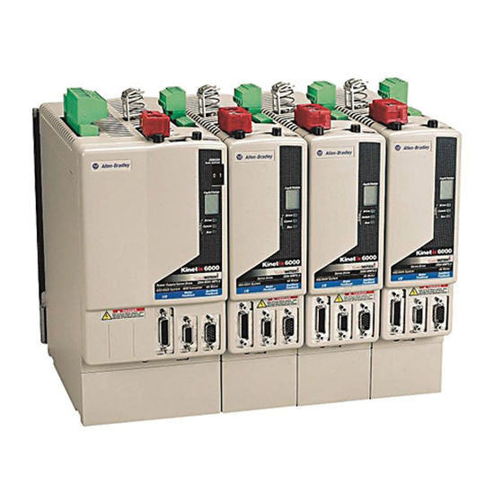
Page 54: Iam/Am Module Features
Drive status indicator Motor/resistive brake (BC) connector COMM status indicator SERCOS communication rate and Bus status indicator optical power switches SERCOS transmit (Tx) connector Motor feedback (MF) connector DPI connector Auxiliary feedback (AF) connector Rockwell Automation Publication 2094-UM001D-EN-P - May 2010... - Page 55 VAC input power (drive) and DC bus 6-position plug/header Contactor enable 2-position plug/header Motor power 4-position plug/header IAM/AM Motor/Resistive brake 6-position plug/header IAM/AM Safe-off 9-position plug/header IAM/AM Tx and Rx SERCOS transmit and receive SERCOS fiber-optic (2) IAM/AM Rockwell Automation Publication 2094-UM001D-EN-P - May 2010...
-
Page 56: Safe-Off Connector Pinout
When wiring to the wiring-plug header, the 24V supply must come from an external source. Refer to the Kinetix Safe-off Feature Safety Reference Manual, publication GMC-RM002, for more information on wiring safe-off headers. Rockwell Automation Publication 2094-UM001D-EN-P - May 2010... -
Page 57: I/O Connector Pinout
IMPORTANT only for the inputs listed above. Figure 24 - Pin Orientation for 26-pin I/O (IOD) Connector 26-pin IAM/AM I/O Connector Pin 18 Pin 9 Pin 26 Pin 19 Pin 1 Pin 10 Rockwell Automation Publication 2094-UM001D-EN-P - May 2010... -
Page 58: Motor Feedback Connector Pinout
(1) Not applicable unless motor has integrated thermal protection. (2) If using 1326AB (resolver-based) motors, use 2090-K6CK-D15MF Low-profile Connector Kits that connect the filtered thermal switch (pins 16 and 17) to MF-11 and MF-6. Rockwell Automation Publication 2094-UM001D-EN-P - May 2010... - Page 59 These limitations also apply when meeting CE requirements. Figure 25 - Pin Orientation for 15-pin Motor Feedback (MF) Connector 15-pin IAM/AM Motor Feedback Connector Pin 10 Pin 15 Pin 5 Pin 11 Pin 1 Pin 6 Rockwell Automation Publication 2094-UM001D-EN-P - May 2010...
-
Page 60: Auxiliary Feedback Connector Pinout
(1) Encoder power supply uses either 5V or 9V DC based on encoder/motor used. Figure 26 - Pin Orientation for 15-pin Auxiliary Feedback (AF) Connector 15-pin IAM/AM Auxiliary Feedback Connector Pin 6 Pin 11 Pin 1 Pin 15 Pin 5 Pin 10 Rockwell Automation Publication 2094-UM001D-EN-P - May 2010... -
Page 61: Iam Input Connector Pinout
Chassis ground. Three-phase input power. Table 25 - Contactor Enable Connector CED Pin Description Signal CONT EN- Relay-driven dry contact used in the safety string for a three-phase power contactor. CONT EN+ Rockwell Automation Publication 2094-UM001D-EN-P - May 2010... -
Page 62: Iam And Am Motor Power And Brake Connector Pinout
BC Pin Description Signal MBRK- Motor brake connections MBRK+ Motor brake common +24V brake input power (from LIM module or customer supplied) DBRK- RBM module connections (from RBM module and safety string) DBRK+ Rockwell Automation Publication 2094-UM001D-EN-P - May 2010... -
Page 63: Control Signal Specifications
REG1 and REG2 21.6V 26.4V On-state current Current flow to guarantee an on-state. 3.0 mA 10.0 mA Voltage applied to the input, with respect to IOCOM, to guarantee an Off-state voltage -1.0V 3.0V off-state. Rockwell Automation Publication 2094-UM001D-EN-P - May 2010... -
Page 64: Sercos Communication Specifications
(1) Node address assignments begin with the IAM module. Node addresses for additional axes on the same power rail are assigned by incrementing from left to right (starting with the IAM module address). Rockwell Automation Publication 2094-UM001D-EN-P - May 2010... -
Page 65: Analog Outputs
1000 2094-xCxx-Mxx or 2094-xMxx -10,000 -1000 10,000 10.0 1000 2094-xCxx-Mxx-S or 2094-xMxx-S -10,000 -1000 For configuration/set up of the analog outputs, refer to Configure Drive Parameters and System Variables beginning on page 153. Rockwell Automation Publication 2094-UM001D-EN-P - May 2010... -
Page 66: Contactor Enable Relay
Current flow when the relay is closed — current On-state 1 Ω Contact resistance when the relay is closed — resistance Off-state 120V AC or Voltage across the contacts when the relay is open — voltage 24V DC Rockwell Automation Publication 2094-UM001D-EN-P - May 2010... -
Page 67: Power And Relay Specifications
5000 software. Refer to RBM Module Interconnect Diagrams beginning on page 259 for wiring examples. Figure 31 - Brake Relay Circuit Kinetix 6000 IAM/AM Module MBRK- DBRK- DBRK+ MBRK+ (BC-4) (BC-6) (BC-3) (BC-2) (BC-5) (BC-1) (1) Noise suppression device. Rockwell Automation Publication 2094-UM001D-EN-P - May 2010... -
Page 68: Input Power Cycle Capability
For example, in a 4 axis system with a 2094-BC02-M02-S IAM module and 2,000 μF total capacitance, the calculated capability is 0.52 x 10,000/2000 = 2.6 cycles per minute. However, this value is reduced to 2.0 by the 4 axes per system limitation. Rockwell Automation Publication 2094-UM001D-EN-P - May 2010... -
Page 69: Peak Enhancement Specifications
250% 200% 250% 2094-BC02-M02-S 150% 250% 200% 250% 2094-BC04-M03-S 150% 250% 200% 250% 2094-BC07-M05-S 150% 200% 200% 300% 2094-BMP5-S 150% 250% 2094-BM01-S 150% 250% 2094-BM02-S 150% 250% 2094-BM03-S 150% 250% 2094-BM05-S 150% 200% Rockwell Automation Publication 2094-UM001D-EN-P - May 2010... - Page 70 These values are collectively defined as the Loading Profile of the drive. The sum of the times at I ) and I Application Period (T) Base (1) All current values are specified as RMS. Rockwell Automation Publication 2094-UM001D-EN-P - May 2010...
- Page 71 Applies to these Kinetix 6000 drives: 2094-BC07-M05-S, 2094-BM05-S 100% % Base Current (I Base Cont (1) Base current (I ) and peak current (I ) are a percentage of the continuous drive current rating (I Base Cont Rockwell Automation Publication 2094-UM001D-EN-P - May 2010...
-
Page 72: Control Power
1.50 0.70 IAM and 2 AM 2.25 IAM and 3 AM 1.35 IAM and 4 AM 3.75 1.70 IAM and 5 AM 4.50 IAM and 6 AM 5.25 2.40 IAM and 7 AM Rockwell Automation Publication 2094-UM001D-EN-P - May 2010... -
Page 73: Feedback Specifications
(-M or -V) encoders, for example, motor catalog number MPL-B310P-M. Figure 35 - Absolute Position Retention Limit 4096 Turns, Kinetix 6000 Drives -2048 -1024 +1024 +2048 Position at Power Down Rockwell Automation Publication 2094-UM001D-EN-P - May 2010... - Page 74 Table 42 - Motor Encoder Feedback Specifications Specification Description Incremental, A quad B, sine/cosine, intelligent, resolver, and Encoder types absolute 5.0 MHz (TTL input) per channel Maximum input frequency 250 kHz (sine/cosine input) Commutation feedback Hall sensor Rockwell Automation Publication 2094-UM001D-EN-P - May 2010...
-
Page 75: Feedback Power Supply Specifications
The IAM and AM power circuit board generates +5V and +9V DC for motor and auxiliary feedback power. Short circuit protection and separate common mode filtering for each channel is included. Voltage Current mA Supply Reference Nominal +5V DC EPWR_5V 5.25 +9V DC EPWR_9V Rockwell Automation Publication 2094-UM001D-EN-P - May 2010... -
Page 76: Auxiliary Position Feedback Encoders
HS35, hollow shaft incremental, 5/8 in. shaft, tether 3/8 in. bolt on, 5V DC, 5V DLD output, 10 pin connector 845T-DN13ECS Refer to the Kinetix Motion Control Selection Guide, publication GMC-SG001, for more information on these Allen-Bradley encoders. Rockwell Automation Publication 2094-UM001D-EN-P - May 2010... -
Page 77: Connecting The Kinetix 6000 Drive System
SHOCK HAZARD: To avoid hazard of electrical shock, perform all mounting and wiring of the Bulletin 2094 power rail and drive modules prior to applying power. Once power is applied, connector terminals may have voltage present even when not in use. Rockwell Automation Publication 2094-UM001D-EN-P - May 2010... -
Page 78: Building Your Own Cables
Refer to Electrical Noise Reduction on page 31 for examples of routing high and low voltage cables in wireways. Refer to the System Design for Control of Electrical Noise Reference Manual, publication GMC-RM001, for more information. Rockwell Automation Publication 2094-UM001D-EN-P - May 2010... -
Page 79: Determine The Input Power Configuration
Connect to power rail Bonded Cabinet ground stud. Ground Ground Grid or Power Distribution Ground Refer to Power Wiring Examples beginning on page 201 for input power interconnect diagrams with and without the LIM module. Rockwell Automation Publication 2094-UM001D-EN-P - May 2010... - Page 80 If you determine that you have grounded power distribution in your plant, IMPORTANT you do not need to modify your IAM module. Refer to Power Wiring Examples beginning on page 201 for input power interconnect diagrams with and without the LIM module. Rockwell Automation Publication 2094-UM001D-EN-P - May 2010...
-
Page 81: Ungrounded Power Configurations
This can result in an unknown potential to earth ground. Refer to Power Wiring Examples beginning on page 201 for input power interconnect diagrams with and without the LIM module. Rockwell Automation Publication 2094-UM001D-EN-P - May 2010... -
Page 82: Dc Common Bus Configurations
DBRK - Input Power CONT EN+ CONT EN+ DBRK + DBRK + BAUD BAUD BAUD BAUD BAUD BAUD RATE RATE RATE RATE RATE Kinetix 6000 RATE DC Common Bus N.C. Connections N.C. N.C. Rockwell Automation Publication 2094-UM001D-EN-P - May 2010... -
Page 83: Common Bus Fusing Requirements
ATTENTION: To avoid personal injury and/or damage to equipment, remove the IAM module from the power rail before setting the ground jumper. By setting the ground jumper for ungrounded power configurations, you no longer maintain line-to-neutral voltage protection. Rockwell Automation Publication 2094-UM001D-EN-P - May 2010... -
Page 84: Set The Ground Jumper
The front panel status indicators and switches are also connected to the IAM module with a ribbon cable. The ribbon cable will act like a hinge and let you swing the front panel open and access the ground jumper. Rockwell Automation Publication 2094-UM001D-EN-P - May 2010... - Page 85 4. Replace the IAM module front panel and two screws. Apply 1.6 N•m (14 lb•in) torque. 5. Mount the IAM module back on the power rail. Refer to Replace Kinetix 6000 Drive Modules on page 175. Rockwell Automation Publication 2094-UM001D-EN-P - May 2010...
- Page 86 (default setting). Front Panel (opened) Bottom Screw Use the default jumper setting or remove the jumper entirely for IMPORTANT grounded power configurations. Move the jumper, as shown above, for ungrounded power. Rockwell Automation Publication 2094-UM001D-EN-P - May 2010...
- Page 87 Ground jumper set for ungrounded configuration. Front Panel (opened) Bottom Screw Use the default jumper setting or remove the jumper entirely for IMPORTANT grounded power configurations. Move the jumper, as shown above, for ungrounded power. Rockwell Automation Publication 2094-UM001D-EN-P - May 2010...
- Page 88 Figure 43 - Setting the Ground Jumper (460V Series-B IAM modules) (behind P18) Top Screw 2094-BC01-MP5- 2094-BC01-M01- 2094-BC02-M02- 2094-BC04-M03- 2094-BC07-M05- Ground jumper set IAM Module (460V) for grounded configuration (default setting). Ground jumper set for ungrounded configuration. Front Panel (opened) Bottom Screw Rockwell Automation Publication 2094-UM001D-EN-P - May 2010...
-
Page 89: Grounding The Kinetix 6000 Drive System
Ground Grid or Power Ground Stud Bonded Cabinet Distribution Ground Ground Bus Braided Ground Strap Ground Grid or Power Distribution Ground For power rail dimensions, refer to the Kinetix 6000 Power Rail Installation Instructions, publication 2094-IN003. Rockwell Automation Publication 2094-UM001D-EN-P - May 2010... -
Page 90: Ground Multiple Subpanels
Figure 45 - Subpanels Connected to a Single Ground Point Follow NEC and applicable local codes. Bonded Ground Bus Ground Grid or Power Distribution Ground High-frequency (HF) bonding is not illustrated. For HF bonding information, refer to Bonding Multiple Subpanels on page Rockwell Automation Publication 2094-UM001D-EN-P - May 2010... -
Page 91: Power Wiring Requirements
Do not use them to turn the unit on and off. To avoid personal injury and/or equipment damage, make sure shielded power cables are grounded to prevent potentially high voltages on the shield. Rockwell Automation Publication 2094-UM001D-EN-P - May 2010... - Page 92 N•m (lb•in) Signal (AWG) RC-1 1394-SRxxxx 1.2…1.5 External passive RC-2 10 (8) (10.6…13.2) 2094-BSP2 shunt module Shunt module RC-3 (230/460V) TS-1 0.22…0.25 Thermal switch 0.75 (18) (1.9…2.2) TS-2 (1) 105 °C (221 °F), 600V. Rockwell Automation Publication 2094-UM001D-EN-P - May 2010...
-
Page 93: Power Wiring Guidelines
4. Tighten the connector screws. 5. Gently pull on each wire to make sure it does not come out of its terminal; reinsert and tighten any loose wires. 6. Insert the connector plug into the module connector. Rockwell Automation Publication 2094-UM001D-EN-P - May 2010... -
Page 94: Wiring The Iam/Am Module Connectors
2094-XL75S-Cx LIM Module LIM Module mm (in.) N•m (lb•in) (AWG) CPL Pin Signal CPL Pin Signal CPD Pin Signal CTRL 1 CTRL 2 0.5…0.6 2.5 (14) 10 (0.38) (4.4…5.3) CTRL 2 L2/N CTRL 1 Rockwell Automation Publication 2094-UM001D-EN-P - May 2010... -
Page 95: Wire The Input Power (Ipd) Connector
(4.4…5.3) 230V AC 2094-AC16-M03-x 10 (8) 2.4…3.0 16 (0.63) (21.6…26.5) 2094-AC32-M05-x 25 (4) 2094-BC01-Mxx-x 1.2…1.5 4.0 (12) 10 (0.38) 2094-BC02-M02-x (10.6…13.2) 460V AC 2094-BC04-M03-x 10 (8) 2.4…3.0 16 (0.63) (21.6…26.5) 2094-BC07-M05-x 25 (4) Rockwell Automation Publication 2094-UM001D-EN-P - May 2010... - Page 96 (4.4…5.3) 230V AC 2094-AC16-M03-x 10 (8) 2.4…3.0 16 (0.63) (21.6…26.5) 2094-AC32-M05-x 25 (4) 2094-BC01-Mxx-x 1.2…1.5 4.0 (12) 10 (0.38) 2094-BC02-M02-x (10.6…13.2) 460V AC 2094-BC04-M03-x 10 (8) 2.4…3.0 16 (0.63) (21.6…26.5) 2094-BC07-M05-x 25 (4) Rockwell Automation Publication 2094-UM001D-EN-P - May 2010...
-
Page 97: Wire The Contactor Enable (Ced) Connector
2.5 (14) 10 (0.38) (4.4…5.3) COIL_E2 COIL_A2 CONT EN+ (1) The actual gauge of the contactor enable wiring depends on the system configuration. Consult your machine builder, the NEC, and applicable local codes. Rockwell Automation Publication 2094-UM001D-EN-P - May 2010... -
Page 98: Wiring The Safe-Off (So) Connector
SAFETY ENABLE- 1.5 (16) (solid wire) SAFETY ENABLE1+ 24V + 24V_COM To wire the safe-off connector in single axis or multi-axis configurations, refer to the Kinetix Safe-off Feature Safety Reference Manual, publication GMC-RM002. Rockwell Automation Publication 2094-UM001D-EN-P - May 2010... -
Page 99: Wire The Motor Power (Mp) Connector
For TL-Series motors, also connect the 152 mm (6.0 in.) termination wire IMPORTANT to the closest earth ground. Refer to Pigtail Terminations on page 100 for more information. Rockwell Automation Publication 2094-UM001D-EN-P - May 2010... - Page 100 Figure 53 - Bayonet and Circular DIN Motor Connectors Circular DIN Connectors Bayonet Connectors Bayonet Connectors with Brake without Brake Power and Brake Feedback Motor Connector Motor Connector Feedback / Power / Brake Feedback / Power Motor Connectors Motor Connectors Rockwell Automation Publication 2094-UM001D-EN-P - May 2010...
- Page 101 (1) For motors with circular DIN connectors, either 2090-CPxM7DF-xxAxxx, 2090-CPxM4DF-xxAFxx, or 2090-XXNPMF-xxSxx cables are compatible. However, you must remove the motor-side o-ring when using 2090-CPxM7DF-xxAxxx cables. (2) For Bulletin MPL or 1326AB motors equipped with bayonet connectors. These cables are available as standard (catalog number 2090-XXNPMP-xxSxx) and continuous-flex (catalog number 2090-XXTPMP-xxSxx). Rockwell Automation Publication 2094-UM001D-EN-P - May 2010...
- Page 102 The cable shield clamp shown above is mounted to an IAM module. Cables attach to the clamp on each AM module in the same way. We recommend securing the cable shield in the clamp with a tie wrap to IMPORTANT improve stress relief. Rockwell Automation Publication 2094-UM001D-EN-P - May 2010...
- Page 103 The cable shield clamp shown above is mounted to an IAM module. Cables attach to the clamp on each AM module in the same way. We recommend securing the cable shield in the clamp with a tie wrap to IMPORTANT improve stress relief. Rockwell Automation Publication 2094-UM001D-EN-P - May 2010...
- Page 104 The cable shield clamp shown above is mounted to an IAM module. Cables attach to the clamp on each AM module in the same way. We recommend securing the cable shield in the clamp with a tie wrap to IMPORTANT improve stress relief. Rockwell Automation Publication 2094-UM001D-EN-P - May 2010...
- Page 105 (4.4…5.3) 2094-AMP5-x, 2094-AM01-x, motor/drive 10 (0.38) 2094-AM02-x, 2094-BMP5-x, combination. 2094-BM01-x, and 2094-BM02-x 6 (10) max 2094-AC16-M03-x 1.2…1.5 2094-AC32-M05-x (10.6…13.2) 2094-AM03-x, 2094-AM05-x 2094-BC04-M03-x 2.4…3.0 2094-BC07-M05-x 25 (4) max 16 (0.63) (21.6…26.5) 2094-BM03-x, 2094-BM05-x Rockwell Automation Publication 2094-UM001D-EN-P - May 2010...
-
Page 106: Wire The Motor/Resistive Brake (Bc) Connector
RBM Module I/O Connections (IAM/AM modules) TB3 Pin Signal MP Pin Signal COIL_A1 DBRK+ COIL_A2 DBRK- (1) Firmware revision 1.071 or later, is required to use the DBRK outputs on the Kinetix 6000 IAM/AM module. Rockwell Automation Publication 2094-UM001D-EN-P - May 2010... - Page 107 (2) For Bulletin MPL and 1326AB motors equipped with bayonet connectors. These cables are available as standard (catalog number 2090-UXNBMP-18Sxx) and continuous-flex (catalog number 2090-UXTBMP-18Sxx). Use surge suppression when controlling a brake coil. Refer to Controlling IMPORTANT a Brake Example on page 224. Rockwell Automation Publication 2094-UM001D-EN-P - May 2010...
- Page 108 BC Connector (IAM/AM module) Recommended Strip Length Torque Value Wire Size mm (in.) N•m (lb•in) BC Pin Signal (AWG) BC-6 MBRK- BC-5 MBRK+ BC-4 0.22…0.25 0.75 (18) 10 (0.38) BC-3 (1.9…2.2) BC-2 DBRK- BC-1 DBRK+ Rockwell Automation Publication 2094-UM001D-EN-P - May 2010...
-
Page 109: Apply The Motor Cable Shield Clamp
Vent holes on top of IAM/AM module. Exposed Braid Outer Insulation (under clamp) Motor Cable Pivot-open Cable Clamp Vent holes on top of IAM/AM module. 5. Repeat steps 1…4 for each IAM and AM module. Rockwell Automation Publication 2094-UM001D-EN-P - May 2010... -
Page 110: Feedback And I/O Cable Connections
114 F-Series Incremental encoder 2090-UXNFBHF-Sxx 2090-XXNFHF-Sxx (1) For Bulletin MPL and 1326AB (M2L/S2L) motors equipped with bayonet connectors. These cables are available as standard (catalog number 2090-XXNFMP-Sxx) and continuous-flex (catalog number 2090-XXTFMP-Sxx). Rockwell Automation Publication 2094-UM001D-EN-P - May 2010... - Page 111 Circular TLY-Axxxx-H Incremental encoder 2090-CFBM6DD-CCAAxx 2090-CFBM6DF-CBAAxx Plastic (1) For motors with circular DIN connectors, either 2090-CFBM7DF-CDAFxx, 2090-CFBM4DF-CDAFxx, or 2090-XXNPMF-Sxx cables are compatible. However, you must remove the motor-side o-ring when using 2090-CFBM7DF-CDAFxx cables. Rockwell Automation Publication 2094-UM001D-EN-P - May 2010...
-
Page 112: Flying-Lead Feedback Cable Pin-Outs
Table 72 - 2090-CDNFDMP-Sxx Feedback Cable Resolver Feedback Motor DIN Drive MF Motor Bayonet Drive MF Resolver Feedback MPL-Bxxxx-R Connector Pin Connector Pin Connector Pin Connector Pin MPL-Bxxxx-R MPM-xxxxxx-2 EPWR_9V EPWR_9V ECOM ECOM Rockwell Automation Publication 2094-UM001D-EN-P - May 2010... - Page 113 Reserved ECOM Reserved Reserved – Reserved Reserved Reserved Reserved Reserved Reserved Table 74 - 2090-CFBM6DF-CBAAxx Feedback Cable Incremental Feedback Rotary Motor Drive MF Connector Pin Connector Pin TLY-Axxxx-H EPWR_5V ECOM Shield Connector housing Rockwell Automation Publication 2094-UM001D-EN-P - May 2010...
- Page 114 (1) For termination of individual drain wires, use Low Profile connector kit (catalog number 2090-K6CK-D15MF) and reference figure on page 119. (2) Thermal switch wires (5 and 9) are in the motor power cable (catalog number1326-CPx1T-L-xxx). Use Low Profile connector kit (catalog number 2090-K6CK-D15MF) and reference figure on page 119. Rockwell Automation Publication 2094-UM001D-EN-P - May 2010...
-
Page 115: Wiring The Feedback And I/O Connectors
(finger tight) to improve system performance. Figure 60 - IAM/AM Module (MF connector) Kinetix 6000, Side View Kinetix 6000, Front View (IAM module is shown) (IAM module is shown) Premolded Connector (2090-UXNFBMP-Sxx Cable Motor Feedback (MF) Connector Rockwell Automation Publication 2094-UM001D-EN-P - May 2010... -
Page 116: Connect Panel-Mounted Breakout Board Kits
Panel-mounted Breakout Board Refer to CN2 Motor Feedback Breakout Board Installation Instructions, publication 2090-IN006, Wire Terminations for connector breakout board specifications. The panel-mounted breakout board kit (2090-UXBK-D15xx) is not IMPORTANT compatible with 1326-CCUT-L-xxx cable. Rockwell Automation Publication 2094-UM001D-EN-P - May 2010... -
Page 117: Wire Low-Profile Connector Kits
(IAM module is shown) Kinetix 6000, Front View (IAM module is shown) 2090-Kxxx-Dxxx Low-profile Connector Kit I/O (IOD) Connector with flying-lead Feedback or I/O Cable Motor Feedback (MF) Connector Auxiliary Feedback (AF) Connector Rockwell Automation Publication 2094-UM001D-EN-P - May 2010... - Page 118 Shield Clamp Refer to Low Profile EnDat Feedback Modules Exposed Braid Under Clamp Installation Instructions, publication 2090-IN020, for connector kit specifications. Turn clamp over to hold Bulletin 2090 small wires secure. Feedback Cable Rockwell Automation Publication 2094-UM001D-EN-P - May 2010...
- Page 119 Low Profile Connector Kit) Refer to Low Profile Connector Kit Installation Instructions, publication 2094-IN007, for connector kit specifications. Tie Wrap Slot Turn clamp over to hold small wires secure. Discrete I/O Wire Three Conductor I/O Cables Rockwell Automation Publication 2094-UM001D-EN-P - May 2010...
-
Page 120: External Shunt Module Connections
Figure 68 - Shunt Module Jumper Settings Kinetix 6000 Shunt Module, Top View Cable Shield (catalog number 2094-BSP2) Clamp Jumpers External Shunt Resistor (RC) Connector External Thermal Switch (TS) Connector (1) These are the default jumper settings. Rockwell Automation Publication 2094-UM001D-EN-P - May 2010... -
Page 121: Rbm Module Connections
MBRK + CONT EN- DBRK - CONT EN+ DBRK + Exposed Shield Braid Under Clamp BAUD Motor Cable RATE Shield Clamps 2090-XXNRB-xxF0Px Bulletin 2090 Motor Power Cable RBM/Kinetix 6000 Interface Cable To Motor Rockwell Automation Publication 2094-UM001D-EN-P - May 2010... -
Page 122: Sercos Fiber-Optic Cable Connections
For more information, refer to Fiber-optic Cable Installation and Handling Instructions, publication 2090-IN010. SoftLogix and ControlLogix platforms are used in the following examples; however, the CompactLogix platform connects in the same manner. Rockwell Automation Publication 2094-UM001D-EN-P - May 2010... - Page 123 SERCOS Fiber-optic Ring Clean the fiber-optic cable connectors prior to installation. Dust in the IMPORTANT connectors can reduce signal strength. For more information, refer to Fiber-optic Cable Installation and Handling Instructions, publication 2090-IN010. Rockwell Automation Publication 2094-UM001D-EN-P - May 2010...
- Page 124 Logix Platform (ControlLogix is shown) SERCOS Fiber-optic Bulkhead Adapter Tx (rear) Rx (front) Transmit Receive SERCOS Fiber-optic Ring SERCOS Ring Transmit Receive Transmit Receive SERCOS Fiber-optic Bulkhead Adapter Kinetix 6000 Kinetix 6000 System System Rockwell Automation Publication 2094-UM001D-EN-P - May 2010...
-
Page 125: Installing The Fiber-Optic Connector Bracket Kit
Push clamp into Fiber-optic Connector bottom-most position. Bracket Kit Clamp must hold connectors tight to be effective. Kinetix 6000 IAM or AM Module Kinetix 6000 AM Module (AM module is shown) Front View Rockwell Automation Publication 2094-UM001D-EN-P - May 2010... - Page 126 Chapter 5 Connecting the Kinetix 6000 Drive System Notes: Rockwell Automation Publication 2094-UM001D-EN-P - May 2010...
-
Page 127: Configure And Start Up The Kinetix 6000 Drive System
Test and Tune the Axes Configure Drive Parameters and System Variables Before you begin, make sure you know the catalog number for each drive component, the Logix module, and the servo motor/actuator in your motion control application. Rockwell Automation Publication 2094-UM001D-EN-P - May 2010... -
Page 128: Configure The Drive Modules
When two or more IAM modules are connected to the same IMPORTANT SERCOS interface module, each node address must be unique. Refer to the node addressing examples beginning on page 130. Rockwell Automation Publication 2094-UM001D-EN-P - May 2010... - Page 129 Switch numbers shown above are Switch in ON Position SERCOS Communication Rate turned around for clarity. and Optical Power Switches 6. Repeat step 4 step 5 for each 2094-xMxx-x AM module. Rockwell Automation Publication 2094-UM001D-EN-P - May 2010...
- Page 130 Slot-filler modules must be used to fill any unoccupied slot on the power IMPORTANT rail. However, you can replace slot-filler modules with AM modules or the 2094-BSP2 shunt module (maximum one 2094-BSP2 shunt module per power rail). Rockwell Automation Publication 2094-UM001D-EN-P - May 2010...
- Page 131 Slot-filler modules must be used to fill any unoccupied slot on the power IMPORTANT rail. However, you can replace slot-filler modules with AM modules or the 2094-BSP2 shunt module (maximum one 2094-BSP2 shunt module per power rail). Rockwell Automation Publication 2094-UM001D-EN-P - May 2010...
- Page 132 AM or shunt module in the future. Do not position axis modules to the right of shunt or slot-filler modules. IMPORTANT The added distance between non-adjacent axes can increase electrical noise and impedance, and requires longer fiber-optic cable lengths. Rockwell Automation Publication 2094-UM001D-EN-P - May 2010...
-
Page 133: Configure The Logix Sercos Interface Module
From the Revision pull-down menu, choose the revision. c. Type the file Name. d. From the Chassis Type pull-down menu, choose the chassis. e. Enter the Logix processor slot. 4. Click OK. 5. From the Edit menu, choose Controller Properties. Rockwell Automation Publication 2094-UM001D-EN-P - May 2010... - Page 134 This assigns the controller as the Grandmaster clock. The motion modules set their clocks to the module you assign as the Grandmaster. You can assign only one module in the Logix chassis as the IMPORTANT Grandmaster clock. 8. Click OK. Rockwell Automation Publication 2094-UM001D-EN-P - May 2010...
-
Page 135: Configure The Logix Module
The New Module dialog box opens. 4. Configure the new module. a. Type the module Name. b. Enter the Logix SERCOS module slot (leftmost slot = 0). c. Check Open Module Properties. 5. Click OK. Rockwell Automation Publication 2094-UM001D-EN-P - May 2010... - Page 136 The Transition to Phase default setting is 4 (phase 4). The Transition to Phase setting stops the ring in the phase specified. 11. Click OK. 12. Repeat step 1…step 11 for each Logix module. Rockwell Automation Publication 2094-UM001D-EN-P - May 2010...
-
Page 137: Configure The Kinetix 6000 Drive Modules
SERCOS interface module (indicated by three solid-green status indicators on the SERCOS module), you must be using RSLogix 5000 software, version 11.0 or later. 3. Click OK. The New Module dialog box opens. Rockwell Automation Publication 2094-UM001D-EN-P - May 2010... - Page 138 7. Click New Axis. The New Tag dialog box opens. 8. Type the axis Name. AXIS_SERVO_DRIVE is the default Data Type. 9. Click OK. The axis appears under the Ungrouped Axes folder in the Controller Organizer. Rockwell Automation Publication 2094-UM001D-EN-P - May 2010...
- Page 139 The Auxiliary Axis (Node 129) is configured identical to Node 1 by clicking New Axis and creating a new tag. 12. Click Apply if you made changes. 13. Click the Power tab. Rockwell Automation Publication 2094-UM001D-EN-P - May 2010...
- Page 140 Refer to Appendix E beginning on page 253, for more information on setting the Add Bus Cap parameter. 15. Click OK. 16. Repeat step 1…step 10 for each Bulletin 2094 AM module. Rockwell Automation Publication 2094-UM001D-EN-P - May 2010...
-
Page 141: Configure The Motion Group
5. Click the Axis Assignment tab and move your axes (created earlier) from Unassigned to Assigned. 6. Click the Attribute tab and edit the default values as appropriate for your application. 7. Click OK. Rockwell Automation Publication 2094-UM001D-EN-P - May 2010... -
Page 142: Configure Axis Properties
The Axis Properties dialog box opens on the General tab. If an axis is associated to the auxiliary axis node, set the Axis Configuration on the General tab of the Axis Properties dialog box to Feedback Only. Rockwell Automation Publication 2094-UM001D-EN-P - May 2010... - Page 143 In this example, an SRM feedback device is being used. 4. From the Feedback Type pull-down menu, choose the feedback type appropriate for your auxiliary feedback motor. 5. Click Apply. Rockwell Automation Publication 2094-UM001D-EN-P - May 2010...
- Page 144 8. Click the Motor Feedback tab and verify the Feedback Type shown is appropriate for your actual hardware configuration. 9. Click the Units tab and edit default values as appropriate for your application. Rockwell Automation Publication 2094-UM001D-EN-P - May 2010...
- Page 145 Type the Brake Release Delay Time. c. Set the Resistive Brake Contact Delay time (0 - 1000 ms range). The recommended delay time for 2090-XB33-xx and 2090-XB120-xx RBM modules is 71 ms. d. Click Close. 15. Click OK. Rockwell Automation Publication 2094-UM001D-EN-P - May 2010...
-
Page 146: Download The Program
4. Set CB2 to the ON position. 5. Go to main step 3. 1. Apply (95…264V AC) control power to the IAM module (CPD Is not sourced from a connector). LIM module 2. Go to main step 3. Rockwell Automation Publication 2094-UM001D-EN-P - May 2010... - Page 147 (1) You can get diagnostic information from the module by highlighting the module name in RSLogix 5000 software. A Pseudo Key Failure often indicates that the motor selection does not match the motor installed. Rockwell Automation Publication 2094-UM001D-EN-P - May 2010...
-
Page 148: Test And Tune The Axes
Follow these steps to test the axes. 1. Verify the load was removed from each axis. 2. Right-click an axis in your Motion Group folder and choose Properties. The Axis Properties dialog box opens. 3. Click the Hookup tab. Rockwell Automation Publication 2094-UM001D-EN-P - May 2010... - Page 149 7. Click OK. The Online Command - Apply Test dialog box opens (Feedback and Command & Feedback tests only). When the test completes, the Command Status changes from Executing to Command Complete. 8. Click OK. Rockwell Automation Publication 2094-UM001D-EN-P - May 2010...
-
Page 150: Tune The Axes
ATTENTION: To reduce the possibility of unpredictable motor response, tune your motor with the load removed first, then re-attach the load and perform the tuning procedure again to provide an accurate operational response. 2. Click the Tune tab. Rockwell Automation Publication 2094-UM001D-EN-P - May 2010... - Page 151 The Tune Bandwidth dialog box opens. Actual bandwidth values (Hz) depend on your application and may require adjustment once motor and load are connected. 9. Record your bandwidth data for future reference. 10. Click OK. Rockwell Automation Publication 2094-UM001D-EN-P - May 2010...
- Page 152 3. Refer to the appropriate Logix motion module user manual for more information. 4. Return to step 7 and run the test again. 13. Repeat Test and Tune the Axes for each axis. Rockwell Automation Publication 2094-UM001D-EN-P - May 2010...
-
Page 153: Configure Drive Parameters And System Variables
Parameters are read-only when the SERCOS ring is active. You must IMPORTANT break the SERCOS ring to change parameters. To save changes, perform a non-volatile save (NVS) prior to cycling power. Figure 79 - DriveExplorer Software Example Rockwell Automation Publication 2094-UM001D-EN-P - May 2010... -
Page 154: Monitor System Variables With Analog Test Points
Figure 80 - Pin Orientation for 26-pin I/O (IOD) Connector 26-pin IAM/AM I/O Connector Pin 18 Pin 9 Pin 26 Pin 19 Pin 1 Pin 10 Refer to Analog Outputs on page 65 for signal specifications. Rockwell Automation Publication 2094-UM001D-EN-P - May 2010... - Page 155 For linear scaling specifications, refer to the table on page Table 83 - Monitor Dynamic System Variables Attribute Parameter Number Velocity feedback xx40 Velocity commanded xx36 Torque feedback xx84 Torque commanded xx80 (1) x = slot number. Rockwell Automation Publication 2094-UM001D-EN-P - May 2010...
- Page 156 Chapter 6 Configure and Start Up the Kinetix 6000 Drive System Notes: Rockwell Automation Publication 2094-UM001D-EN-P - May 2010...
-
Page 157: Troubleshooting The Kinetix 6000 Drive System
ATTENTION: Provide an earth ground for test equipment (oscilloscope) used in troubleshooting. Failure to ground the test equipment could result in personal injury. Rockwell Automation Publication 2094-UM001D-EN-P - May 2010... -
Page 158: Interpret Status Indicators
Refer to these troubleshooting tables to identify faults, potential causes, and the appropriate actions to resolve the fault. If the fault persists after attempting to troubleshoot the system, please contact your Rockwell Automation sales representative for further assistance. Error Codes The following list of problematic symptoms (no error code shown) and faults with assigned error codes is designed to help you resolve anomalies. - Page 159 • Verify the Hall wiring at the MF MotFeedbackFault State of Hall feedback connector on the IAM/AM module. Improper connections. inputs is incorrect. (Illegal Hall State) • Verify 5V power supply to the encoder. Rockwell Automation Publication 2094-UM001D-EN-P - May 2010...
- Page 160 Excessive heat exists in the power • Use larger IAM converter module. tripped. circuitry. (System Overtemperature) • Check for clogged vents or defective fan. • Make sure cooling is not restricted by insufficient space around the unit. Rockwell Automation Publication 2094-UM001D-EN-P - May 2010...
- Page 161 (Mtr Fdbk Noise) publication GMC-RM001. No Fault Message • Check motor power/feedback wiring. (condition indicated by Hookup procedure failed Motor or feedback device malfunction. • Refer to on-screen message for on-screen message) resolution. (Hookup Fault) Rockwell Automation Publication 2094-UM001D-EN-P - May 2010...
- Page 162 460V AM module is installed on power rail with 230V IAM Replace mismatched module. (Module Mismatch) module. DriveHardFault • Cycle power. Control hardware fault detected. • If fault persists, replace module. (SERCOS Init) Rockwell Automation Publication 2094-UM001D-EN-P - May 2010...
- Page 163 Remove AC input power connections from Follower IAM module detected AC input power being applied. follower IAM module. (Common Bus Flt) DriveHardFault Pre-charge resistor power exceeds the resistor rating. Wait for resistor to cool. (Pre-charge Timeout Flt) Rockwell Automation Publication 2094-UM001D-EN-P - May 2010...
-
Page 164: Iam/Am Module Status Indicators
• MSO instruction is not commanded in RSLogix 5000 software. Normal when: Bus power is present, axis enabled. Steady green • 24V is applied to Hardware Enable Input (IOD-2). No faults. • MSO instruction is commanded in RSLogix 5000 software. Rockwell Automation Publication 2094-UM001D-EN-P - May 2010... -
Page 165: Shunt Module Status Indicators
Drive (IAM or leader IAM module) three-phase power is removed. DC bus. Disabled from discharging When configured in Common-bus Follower mode. the DC bus. Under some fault conditions, two reset commands may be required to IMPORTANT clear drive and shunt module faults. Rockwell Automation Publication 2094-UM001D-EN-P - May 2010... - Page 166 Potential Cause Possible Resolution Indicator • Bus Status • Cycle power. All three status indicators • Over-Temp Fault Shunt module hardware failure. flash simultaneously. • If anomaly persists, replace shunt module. • Shunt Fault Rockwell Automation Publication 2094-UM001D-EN-P - May 2010...
-
Page 167: General System Anomalies
Primary operation mode is set incorrectly. Check and properly set the limit. Velocity or current limits are set incorrectly. Check and properly set the limits. Rockwell Automation Publication 2094-UM001D-EN-P - May 2010... - Page 168 Sine, Cosine or Rotor leads are reversed in the feedback cable Check and correct motor feedback wiring. without control or with connector. reduced torque. Sine, Cosine, Rotor lead sets of resolver feedback are reversed. Check and correct motor feedback wiring. Rockwell Automation Publication 2094-UM001D-EN-P - May 2010...
-
Page 169: Logix/Drive Fault Behavior
Only selected faults are programmable. In the Logix/Drive Fault Behavior table page 170, the controlling attribute is given for programmable fault actions. Figure 81 - RSLogix 5000 Axis Properties - Fault Actions Tab Drive Fault Action/Attribute for Motor Overtemp fault (E04). Rockwell Automation Publication 2094-UM001D-EN-P - May 2010... - Page 170 (Motor Feedback Comm) GroundShortFault Excessive ground current in the converter was detected. SHUTDOWN (Ground Fault) DriveUndervoltageFault The converter pre-charge cycle has failed. SHUTDOWN (Precharge Fault) DriveOvertempFault Converter internal temperature limit exceeded. SHUTDOWN (System Overtemperature) Rockwell Automation Publication 2094-UM001D-EN-P - May 2010...
- Page 171 DriveHardFault Operating system failed. SHUTDOWN (Task init) DriveHardFault DPI communication failed. STOP MOTION (SCANport Comm) DriveHardFault Non-volatile memory attribute out of range. SHUTDOWN (Objects Init) DriveHardFault Non-volatile memory corrupted. SHUTDOWN (NV Mem Init) Rockwell Automation Publication 2094-UM001D-EN-P - May 2010...
- Page 172 (2) The Logix Drive Thermal Fault Action is tied to the drive thermostat fault. The drive will always fold back the current when the I T calculation indicates that the drive has exceeded 110% of its rating. The I T calculation never generates a fault. Rockwell Automation Publication 2094-UM001D-EN-P - May 2010...
-
Page 173: Introduction
ESD awareness handbook. Before You Begin You will need these tools available before you begin removal and replacement procedures: • A screwdriver • A small screwdriver, 3.5 mm (0.14 in.) • Voltmeter Rockwell Automation Publication 2094-UM001D-EN-P - May 2010... -
Page 174: Remove Kinetix 6000 Drive Modules
5. Loosen the mounting screw (bottom center of each module). 6. Grasp top and bottom of the module with both hands and gently pull the module away from the connectors enough to clear the guide pins (module will pivot on top bracket). Rockwell Automation Publication 2094-UM001D-EN-P - May 2010... -
Page 175: Replace Kinetix 6000 Drive Modules
AM module can have one or two, all other modules have only one connector and one guide pin. 5. Use 2.26 N•m (20 lb•in) torque to tighten the mounting screw. 6. Reconnect the module connectors. Rockwell Automation Publication 2094-UM001D-EN-P - May 2010... -
Page 176: Remove The Power Rail
100 mm (3.9 in.) Power Rail 2094-PRSx Bonded Cabinet Ground 2. Loosen the mounting bolts (removing the bolts is not necessary). 3. Lift the power rail up and off of the mounting bolts. Rockwell Automation Publication 2094-UM001D-EN-P - May 2010... -
Page 177: Replace The Power Rail
To improve the bond between the power rail and subpanel, IMPORTANT construct your subpanel out of zinc plated (paint-free) steel. 2. Tighten the mounting bolts. 3. Reattach the braided grounding strap to the power rail grounding stud (refer to page 176). Rockwell Automation Publication 2094-UM001D-EN-P - May 2010... - Page 178 Chapter 8 Removing and Replacing the Kinetix 6000 Drive Modules Notes: Rockwell Automation Publication 2094-UM001D-EN-P - May 2010...
-
Page 179: Introduction
This appendix provides product specifications and mounting dimensions for your Kinetix 6000 system components. Topic Page Introduction Power Specifications Power Dissipation Specifications General Specifications AC Line Filter Specifications External Shunt Module Specifications Product Dimensions Rockwell Automation Publication 2094-UM001D-EN-P - May 2010... -
Page 180: Power Specifications
Refer to Input Power Cycle Capability on page 68, when making calculations. (2) Maximum inrush duration is less than 1/2 line cycle. (3) Peak output current duration equals 250 ms. Rockwell Automation Publication 2094-UM001D-EN-P - May 2010... - Page 181 (3) Peak output current duration equals 250 ms. (4) Converter peak output duration equals 400 ms with a duty cycle of 16%. (5) Converter peak output duration equals 200 ms with a duty cycle of 3%. Rockwell Automation Publication 2094-UM001D-EN-P - May 2010...
-
Page 182: Axis Module (Inverter) Power Specifications
29 J 50 J 99 J absorption Short circuit current rating 200,000 A (rms) symmetrical (1) Bandwidth values vary based on tuning parameters and mechanical components. (2) Peak current duration equals 2.5 seconds. Rockwell Automation Publication 2094-UM001D-EN-P - May 2010... - Page 183 (3) Applies to Series B drives when configured for peak-enhanced mode. For more information on drive performance in the peak-enhanced mode, refer to Peak Enhancement Specifications on page Rockwell Automation Publication 2094-UM001D-EN-P - May 2010...
-
Page 184: Shunt Module Power Specifications
IMPORTANT combination with the 2094-AC09-M02-x IAM module, disables the internal IAM module shunt resistor. This situation is unique to the 2094-AC09-M02-x IAM module. Shunt resistors internal to adjacent AM modules are not disabled. Rockwell Automation Publication 2094-UM001D-EN-P - May 2010... - Page 185 (4) 200 plus the sum of the AM module internal shunt ratings. (5) 200 plus the sum of the IAM and AM module internal shunt ratings. (6) Use of external shunt disables internal IAM/AM shunt modules. Rockwell Automation Publication 2094-UM001D-EN-P - May 2010...
- Page 186 2094-BSP2 200 W Shunt Module 2094-BMP5-x AM Module, 50 W Internal Shunt 2094-BM01-x AM Module, 50 W Internal Shunt 2094-BM01-x AM Module, 50 W Internal Shunt 2094-BC02-M02-x IAM Module, 50 W Internal Shunt Rockwell Automation Publication 2094-UM001D-EN-P - May 2010...
-
Page 187: Circuit Breaker/Fuse Specifications
These devices are designed to operate on sine wave voltage and the drive’s PWM waveform does not allow it to operate properly. As a result, damage to the device will occur. Rockwell Automation Publication 2094-UM001D-EN-P - May 2010... -
Page 188: Contactor Ratings
100-C60x10 (AC coil) 2094-BC04-M03-x 100-C60Zx10 (DC coil) 100-C72x10 (AC coil) 2094-BC07-M05-x 100-C72Zx10 (DC coil) Transformer Specifications for Control Power Input Attribute Value (460V system) Input volt-amperes 750VA Input voltage 460V AC Output voltage 120…240V AC Rockwell Automation Publication 2094-UM001D-EN-P - May 2010... -
Page 189: Power Dissipation Specifications
Power dissipation specifications are based on these calculations. For example: 2094-BC02-M02-x with 4.52 A (=20%) converter DC current and 10.3 A (=100%) inverter output current. Converter loss (36 W) + Inverter loss (142 W) = 178 W total power dissipation. Rockwell Automation Publication 2094-UM001D-EN-P - May 2010... -
Page 190: General Specifications
90 (295.3) MPM-A/Bxxxxx-2 90 (295.3) MPF-Axxxx-S/M 30 (98.4) MPF-Bxxxx-S/M 90 (295.3) MPS-Axxxx-S/M 30 (98.4) MPS-Bxxxx-S/M 90 (295.3) 1326AB-Bxxxx-M2L/S2L 90 (295.3) 1326AB-Bxxxx-21 90 (295.3) RDB-B215xx-7/3 30 (98.4) RDB-B290xx-7/3 or 90 (295.3) RDB-B410xx-7/3 TLY-Axxxx-H 30 (98.4) Rockwell Automation Publication 2094-UM001D-EN-P - May 2010... -
Page 191: Maximum Power Cable Length
240 m (787 ft) with 460V systems or 160 m (525 ft) with 230V systems. Drive-to-motor power cables must not exceed 90 m (295.5 ft). System performance was tested at these cable length specifications. IMPORTANT These limitations also apply when meeting CE requirements. Rockwell Automation Publication 2094-UM001D-EN-P - May 2010... -
Page 192: Weight Specifications
General principles for design. (1) When product is marked, refer to http://www.ab.com for Declarations of Conformity Certificates. (2) Underwriters Laboratories Inc. has not evaluated the safe-off, safe torque-off, or safe speed-monitoring options in these products. Rockwell Automation Publication 2094-UM001D-EN-P - May 2010... -
Page 193: Environmental Specifications
(20.9) Table 112 - AC Line Filter Selection IAM Module AC Line Filter Cat. No. Cat. No. 2094-AC05-MP5-x 2094-AC05-M01-x 2090-XXLF-X330B 2094-AC09-M02-x 2094-AC16-M03-x 2090-XXLF-375 2094-AC32-M05-x 2090-XXLF-3100 2094-BC01-MP5-x 2094-BC01-M01-x 2090-XXLF-X330B 2094-BC02-M02-x 2094-BC04-M03-x 2090-XXLF-375B 2094-BC07-M05-x 2090-XXLF-3100 Rockwell Automation Publication 2094-UM001D-EN-P - May 2010... -
Page 194: External Shunt Module Specifications
4.08 (9) A70Q 1336-WB009 37.0 3.18 (7) A60Q (1) Customer-supplied component. Refer to the Common DC Bus Selection Guide, publication DRIVES-SG001, for dimensions and catalog number information for the Bulletin 1336 active shunt modules. Rockwell Automation Publication 2094-UM001D-EN-P - May 2010... -
Page 195: Product Dimensions
(in.) mm (in.) mm (in.) mm (in.) 2094-AC05-MP5-x 2094-AC05-M01-x 198 (7.8) 176 (7.0) 51 (2.0) 206 (8.2) 231 (9.1) 2094-AC09-M02-x 2094-BC01-MP5-x 2094-BC01-M01-x 272 (10.7) 249 (9.8) 0 (0) 256 (10.1) 281 (11.0) 2094-BC02-M02-x Rockwell Automation Publication 2094-UM001D-EN-P - May 2010... - Page 196 (in.) mm (in.) 2094-AC16-M03-x 125 (4.9) 198 (7.8) 176 (7.0) 302 (11.9) 420 (16.5) 2094-AC32-M05-x 196 (7.7) 2094-BC04-M03-x 256 (10.1) 374 (14.7) 272 (10.7)) 249 (9.8) 196 (7.7) 2094-BC07-M05-x 318 (12.5) 436 (17.2) Rockwell Automation Publication 2094-UM001D-EN-P - May 2010...
- Page 197 (in.) mm (in.) mm (in.) mm (in.) 2094-AMP5-x 2094-AM01-x 198 (7.8) 176 (7.0) 51 (2.0) 206 (8.2) 231 (9.1) 2094-AM02-x 2094-BMP5-x 2094-BM01-x 272 (10.7) 249 (9.8) 0 (0) 256 (10.1) 281 (11.0) 2094-BM02-x Rockwell Automation Publication 2094-UM001D-EN-P - May 2010...
- Page 198 (in.) mm (in.) mm (in.) 2094-AM03-x 198 (7.8) 176 (7.0) 70 (2.8) 302 (11.9) 420 (16.5) 2094-AM05-x 2094-BM03-x 256 (10.1) 374 (14.7) 272 (10.7) 249 (9.8) 141 (5.5) 2094-BM05-x 318 (12.5) 436 (17.2) Rockwell Automation Publication 2094-UM001D-EN-P - May 2010...
-
Page 199: Introduction
Introduction Interconnect Diagram Notes Power Wiring Examples DC Common Bus Wiring Examples Shunt Module Wiring Examples Axis Module/Rotary Motor Wiring Examples Axis Module/Linear Motor/Actuator Wiring Examples Controlling a Brake Example System Block Diagrams Rockwell Automation Publication 2094-UM001D-EN-P - May 2010... -
Page 200: Interconnect Diagram Notes
Brake connector pins are labeled plus (+) and minus (-) or F and G respectively. Power connector pins are labeled U, V, W, and GND or A, B, C, and D respectively. Only the MPL-A5xx encoders use the +9V DC supply. MPL-A3xx, MPL-A4xx, MPL-A45xx encoders use the +5V DC supply. Rockwell Automation Publication 2094-UM001D-EN-P - May 2010... -
Page 201: Power Wiring Examples
IO_PWR Resistive Brake Connections DBRK + I/O (IOL) STOP * Connector Notes 13, 14 COIL_A1 20-22 Contactor Enable IO_COM CONT EN- (CED) Connector COIL_A2 CONT EN+ Note 14 * Indicates User Supplied Component Rockwell Automation Publication 2094-UM001D-EN-P - May 2010... - Page 202 Resistive Brake Connector Connections COIL_E1 Notes 13, 14 2, 4, 6 IO_COM1 CONT EN- Contactor Enable (CED) Connector CONT EN+ COIL_E2 Note 14 To CED Connector * Indicates User Supplied Component IAM_2 Note 7 Rockwell Automation Publication 2094-UM001D-EN-P - May 2010...
- Page 203 Motor/Resistive From P1L connector, LIM Brake (BC) Connector DBRK - Resistive Brake Connections DBRK + CONT EN- Contactor Enable From IOL connector, LIM (CED) Connector and CED connector, IAM_1 CONT EN+ Note 14 Rockwell Automation Publication 2094-UM001D-EN-P - May 2010...
- Page 204 START * Note 14 24V AC/DC CR1 * 120V AC M1 * CR1 * 50/60 Hz Ground Jumper Note 11 CR1 * * Indicates User Supplied Component Refer to Attention statement (Note 13). Rockwell Automation Publication 2094-UM001D-EN-P - May 2010...
-
Page 205: Dc Common Bus Wiring Examples
Interconnect Diagrams Appendix B DC Common Bus Wiring Examples Figure 90 Leader IAM Module with Single Follower IAM Module Rockwell Automation Publication 2094-UM001D-EN-P - May 2010... - Page 206 Contactor Enable CONT EN- (CED) Connector CONT EN+ Note 14 To Follower Control Circuit Connections Wire the leader and follower IAM contactor enable terminals in series with the safety control string or LIM I/O. Rockwell Automation Publication 2094-UM001D-EN-P - May 2010...
- Page 207 N.C. MBRK - MBRK + Motor/Resistive Brake (BC) Connector DBRK - DBRK + From Leader Control Circuit Contactor Enable CONT EN- Connections (CED) Connector CONT EN+ Note 14 * Indicates User Supplied Component Rockwell Automation Publication 2094-UM001D-EN-P - May 2010...
- Page 208 Appendix B Interconnect Diagrams Figure 92 8720MC-RPS Leader Drive with Single Follower IAM Module Rockwell Automation Publication 2094-UM001D-EN-P - May 2010...
-
Page 209: Shunt Module Wiring Examples
Kinetix 6000 shunt module. If your external passive shunt does not have a thermal switch, leave the jumper (default configuration) in place on the TS connector. Refer to the External Shunt Module Installation Instructions, publication 2090-IN004, for additional installation information. Rockwell Automation Publication 2094-UM001D-EN-P - May 2010... - Page 210 Normally-closed contact, TTL compatible, closed when power is Description applied, open when a brake fault or loss of power occurs. 1.0 A, 125V AC UL/CSA rating 1.0 A, 110V AC 2.0 A, 30V DC Initial contact resistance 100 mΩ, max Rockwell Automation Publication 2094-UM001D-EN-P - May 2010...
- Page 211 (+) Slave In (+) Master Out (–) Master Out Shunt Chassis Ground Screw 1336 Slave Resistor * Thermal Switch Refer to the 1336 Chopper Module Installation Instructions, publication 1336-5.65, for additional installation information. Rockwell Automation Publication 2094-UM001D-EN-P - May 2010...
-
Page 212: Axis Module/Rotary Motor Wiring Examples
Turn clamp over to hold for proper grounding technique. small cables secure. Motor Brake 2090-CDNFDMP-Sxx Refer to Low Profile Connector Kit Installation Instructions, (flying-lead) Feedback Cable publication 2094-IN007, for connector kit specifications. Note 16 Rockwell Automation Publication 2094-UM001D-EN-P - May 2010... - Page 213 Turn clamp over to hold for proper grounding technique. small cables secure. 2090-XXxFMP-Sxx Refer to Low Profile Connector Kit Installation Instructions, (flying-lead) Feedback Cable publication 2094-IN007, for connector kit specifications. Notes 16, 17 Rockwell Automation Publication 2094-UM001D-EN-P - May 2010...
- Page 214 (lower left) small cables secure. for proper grounding technique. 2090-XXNFMF-Sxx (standard) or Refer to Low Profile Connector Kit Installation Instructions, 2090-CFBMxDF-CDAFxx (continuous-flex) publication 2094-IN007, for connector kit specifications. (flying-lead) Feedback Cable Notes 16, 19 Rockwell Automation Publication 2094-UM001D-EN-P - May 2010...
- Page 215 Low-profile Connector Kit Clamp Exposed shield secured under clamp. Clamp Screws (2) Turn clamp over to hold small cables secure. Refer to Low Profile Connector Kit Installation Instructions, publication 2094-IN007, for connector kit specifications. Rockwell Automation Publication 2094-UM001D-EN-P - May 2010...
- Page 216 Low-profile Feedback Module Clamp Exposed shield secured under clamp. Clamp Screws (2) Turn clamp over to hold small cables secure. Refer to Low Profile EnDat Feedback Module Installation Instructions, publication 2090-IN020, for connector kit specifications. Rockwell Automation Publication 2094-UM001D-EN-P - May 2010...
- Page 217 Low-profile Connector Kit Clamp Exposed shield secured under clamp. Clamp Screws (2) Turn clamp over to hold small cables secure. Refer to Low Profile Connector Kit Installation Instructions, publication 2094-IN007, for connector kit specifications. Rockwell Automation Publication 2094-UM001D-EN-P - May 2010...
- Page 218 Low-profile connector kit and wire extension to the power connector. Pins 16, 17, and S are filtered to prevent noise transmission back to the drive. Refer to page 119 for wiring instructions and a diagram. Rockwell Automation Publication 2094-UM001D-EN-P - May 2010...
- Page 219 Low-profile Connector Kit Clamp Exposed shield secured under clamp. Clamp Screws (2) Turn clamp over to hold small cables secure. Refer to Low Profile Connector Kit Installation Instructions, publication 2094-IN007, for connector kit specifications. Rockwell Automation Publication 2094-UM001D-EN-P - May 2010...
-
Page 220: Axis Module/Linear Motor/Actuator Wiring Examples
Refer to Low Profile Connector Kit Installation Instructions, Motor Brake WHT/YELLOW publication 2094-IN007, for connector kit specifications. Refer to low profile connector illustration (lower left) for proper grounding technique. 2090-XXNFMF-Sxx (standard) or 2090-CFBM4DF-CDAFxx (continuous-flex) (flying-lead) Feedback Cable Notes 16, 19 Rockwell Automation Publication 2094-UM001D-EN-P - May 2010... - Page 221 Table 120 - MP-Series Electric Cylinder Power and Feedback Cables MP-Series Electric Cylinder Power Cable Feedback Cable Cat. No. Cat. No. Cat. No. MPAR-A/B1xxx 2090-XXNFMF-Sxx (standard) 2090-CPxM4DF-16AFxx 2090-CFxM4DF-16AFxx MPAR-A/B2xxx (continuous-flex) MPAR-A/B3xxx 2090-XXNFMF-Sxx (standard) 2090-CPxM7DF-16AFxx 2090-CFxM7DF-16AFxx MPAI-A/Bxxxxx (continuous-flex) Rockwell Automation Publication 2094-UM001D-EN-P - May 2010...
- Page 222 Low-profile Connector Kit Clamp Exposed shield secured under clamp. Clamp Screws (2) Turn clamp over to hold small cables secure. Refer to Low Profile Connector Kit Installation Instructions, publication 2094-IN007, for connector kit specifications. Rockwell Automation Publication 2094-UM001D-EN-P - May 2010...
- Page 223 Low-profile Connector Kit Clamp Exposed shield secured under clamp. Clamp Screws (2) Turn clamp over to hold small cables secure. Refer to Low Profile Connector Kit Installation Instructions, publication 2094-IN007, for connector kit specifications. Rockwell Automation Publication 2094-UM001D-EN-P - May 2010...
-
Page 224: Controlling A Brake Example
MPL-B640, MPL-B660, MPL-B680 1.91…2.19 A MPL-B860, MPL-B880 2.05…2.50 A MPM-x215 1.84…2.25 A MPL-B960, MPL-B980 Because the coil current for MPL-B960 and MPL-B980 motors is rated IMPORTANT 3.85…4.70 A, an external relay must be used. Rockwell Automation Publication 2094-UM001D-EN-P - May 2010... -
Page 225: System Block Diagrams
This section provides block diagrams of the Kinetix 6000 drive modules. For block diagrams of the LIM module and RBM module, refer to Additional Resources on page 12 for the documentation available for those products. Figure 109 IAM/AM Module (inverter) Block Diagram Rockwell Automation Publication 2094-UM001D-EN-P - May 2010... - Page 226 Appendix B Interconnect Diagrams Figure 110 IAM Module (converter) Block Diagram Rockwell Automation Publication 2094-UM001D-EN-P - May 2010...
- Page 227 Gate Control Enable Signal Wiring Header +24V DRIVE ENABLE +24V_COM Figure 112 Shunt Module Block Diagram Internal or External Shunt Resistor SYSOK Shunt Circuit SMPS GSHUNT (2) +5V (Control) +/-15V (IGBT) 24V (Control) Chassis Rockwell Automation Publication 2094-UM001D-EN-P - May 2010...
- Page 228 Appendix B Interconnect Diagrams Notes: Rockwell Automation Publication 2094-UM001D-EN-P - May 2010...
-
Page 229: Introduction
Upgrading the Kinetix 6000 Drive Firmware Introduction This appendix provides procedures for upgrading firmware by using either ControlFLASH or DriveExplorer software. Topic Page Introduction Upgrade Drive Firmware with ControlFLASH Software Upgrade Drive Firmware with DriveExplorer Software Rockwell Automation Publication 2094-UM001D-EN-P - May 2010... -
Page 230: Upgrade Drive Firmware With Controlflash Software
AM module must be displaying a fixed 2, 3, or 4 before beginning this procedure. ATTENTION: To avoid personal injury or damage to equipment during the firmware upgrade due to unpredictable motor activity, do not apply three-phase AC or common-bus DC input power to the drive. Rockwell Automation Publication 2094-UM001D-EN-P - May 2010... -
Page 231: Configure Logix Communication
3. From the Available Drive Types pull-down menu, choose Ethernet devices. 4. Click Add New. The Add New RSLinx Classic Driver dialog box opens. 5. Type the new driver name. 6. Click OK. Rockwell Automation Publication 2094-UM001D-EN-P - May 2010... - Page 232 7. Type the IP address of your Logix Ethernet module. The IP address shown is an example. Yours will be different. 8. Click OK. The new Ethernet driver appears under Configured Drivers. 9. Click Close. 10. Minimize the RSLinx application dialog box. Rockwell Automation Publication 2094-UM001D-EN-P - May 2010...
-
Page 233: Flash Firmware
• From the Tools menu in RSLogix 5000 software, choose ControlFLASH. • Choose Start>Programs>FLASH Programming Tools> ControlFLASH. The Welcome to ControlFLASH dialog box opens. 2. Click Next. The Catalog Number dialog box opens. Rockwell Automation Publication 2094-UM001D-EN-P - May 2010... - Page 234 5. Expand your Ethernet node, Logix backplane, and EtherNet/IP network module. 6. Select the servo drive to flash. 7. Click OK. The Firmware Revision dialog box opens. 8. Select the firmware revision to flash. 9. Click Next. Rockwell Automation Publication 2094-UM001D-EN-P - May 2010...
- Page 235 10. Confirm the drive catalog number and firmware revision. 11. Click Finish. This ControlFLASH warning dialog box opens. 12. Click Yes (only if you are ready). This ControlFLASH warning dialog box opens. 13. Acknowledge the warning and click OK. Rockwell Automation Publication 2094-UM001D-EN-P - May 2010...
- Page 236 Success 2. Go to step 1. Update failure appears in a RED Status dialog box. Failure 2. Refer to ControlFLASH Firmware Upgrade Kit Quick Start, publication 1756-QS105, for troubleshooting information. 16. Click OK. Rockwell Automation Publication 2094-UM001D-EN-P - May 2010...
-
Page 237: Verify The Firmware Upgrade
3. Expand your Ethernet node, Logix backplane, and EtherNet/IP network module. 4. Right-click the drive module and choose Device Properties. The Device Properties dialog box opens. 5. Verify the new firmware revision level. 6. Click Close. Rockwell Automation Publication 2094-UM001D-EN-P - May 2010... -
Page 238: Upgrade Drive Firmware With Driveexplorer Software
Personal computer with HyperTerminal software (1) Refer to DriveExplorer Getting Results Manual, publication 9306-GR001, for instructions. (2) Contact Rockwell Automation Technical Support at (440) 646-5800 for firmware upgrade file. Control power must be present at CPD-1 and CPD-2 prior to flashing your IMPORTANT drive. - Page 239 Network Node Number 6. Scroll down to parameter x:x.30 (Version Data) and record the version (VERS: xx.xxx) of each axis module. 7. Double-click Configuration. This dialog box opens. 8. Double-click Axes to Flash. Rockwell Automation Publication 2094-UM001D-EN-P - May 2010...
-
Page 240: Hyperterminal Configuration
1. From the Windows Start menu, choose Programs\Accessories\ HyperTerminal\HyperTerminal. The New Connection dialog box opens. 2. Type a name the new HyperTerminal file and choose an icon for the connection. 3. Click OK. Rockwell Automation Publication 2094-UM001D-EN-P - May 2010... - Page 241 6. Choose the properties as shown above or as appropriate for your 1203-SSS SCANport adapter. Bits per second of HyperTerminal must match the 1203-SSS IMPORTANT SCANport adapter setting for connection to occur. 7. Click OK. 8. HyperTerminal configuration is complete. Rockwell Automation Publication 2094-UM001D-EN-P - May 2010...
-
Page 242: Flash Firmware
Axes to Flash parameter, and have configured a HyperTerminal session. IMPORTANT You must also know where to find your firmware upgrade file. 1. Press ENTER. The HyperTerminal main menu opens. 2. Enter 3. This dialog box opens. 3. Enter 0. Rockwell Automation Publication 2094-UM001D-EN-P - May 2010... - Page 243 The Send File dialog box opens. Firmware upgrade file, as provided by Rockwell Automation Technical Support at (440) 646-5800. 6. Browse for your firmware upgrade file. 7. From the Protocol pull-down menu, choose Xmodem. 8. Click Send. Rockwell Automation Publication 2094-UM001D-EN-P - May 2010...
- Page 244 10. Verify that parameter 30 for each axis module is now upgraded to the new firmware revision. Return to DriveExplorer software (refer to Select Axis Modules to Upgrade, page 239) to see the linear list of parameters. Rockwell Automation Publication 2094-UM001D-EN-P - May 2010...
-
Page 245: Introduction
Before you set the Additional Bus Capacitance (Add Bus Cap) parameter in DriveExplorer or RSLogix 5000 software, you need to calculate these values: • Total bus capacitance • Additional bus capacitance Rockwell Automation Publication 2094-UM001D-EN-P - May 2010... -
Page 246: Calculate Total Bus Capacitance
If your total bus capacitance value exceeds the value in the table above, IMPORTANT you must increase the size of the leader IAM module or decrease the total bus capacitance by removing AM modules. Rockwell Automation Publication 2094-UM001D-EN-P - May 2010... -
Page 247: Calculate Additional Bus Capacitance
Capacitance Capacitance IAM Converter (460V) AM Inverter (460V) µF µF 2094-BC01-MP5-x 2094-BMP5-x 2094-BC01-M01-x 2094-BM01-x 2094-BC02-M02-x 2094-BM02-x 2094-BC04-M03-x 2094-BM03-x 2094-BC07-M05-x 1410 2094-BM05-x 1175 Table 127 - Shunt Module (230/460V) Capacitance SM (230-460V) µF 2094-BSP2 Rockwell Automation Publication 2094-UM001D-EN-P - May 2010... -
Page 248: Common Bus Capacitance Example
Kinetix 6000 (230V) Follower IAM Module 5280 µF Additional Bus Capacitance 2094-PRF Slot-filler Module, N/A 2094-AM03-x AM Module, 1320 µF 2094-AM03-x AM Module, 1320 µF 2094-AC16-M03-x IAM Converter, 1320 µF 2094-AC16-M03-x IAM Inverter, 1320 µF Rockwell Automation Publication 2094-UM001D-EN-P - May 2010... -
Page 249: Set The Additional Bus Capacitance Parameter With
1. Remove three-phase and control power from the Kinetix 6000 drive system. 2. Remove one of the SERCOS fiber-optic cables. Fiber-optic cable connections (Tx and Rx) are located on the top of each IAM/AM module. 3. Re-apply three-phase and control power. Rockwell Automation Publication 2094-UM001D-EN-P - May 2010... -
Page 250: Set The Additional Bus Capacitance Parameter
2 = AM (axis 3) 3 = AM (axis 4) DPI Port Number Network Node Number 4. Choose Devices>Node>Product and navigate to the parameter x:x:x599 as shown below. 5. Double-click the x:x:x599 Add Bus Cap parameter. Rockwell Automation Publication 2094-UM001D-EN-P - May 2010... -
Page 251: Save The Add Bus Cap Parameter To Non-Volatile Memory
1. From the Actions menu, choose Non-volatile Memory. This message dialog box opens. 2. Click Save. The changes are saved to non-volatile memory and this cautionary message dialog box opens. 3. Click Yes. Rockwell Automation Publication 2094-UM001D-EN-P - May 2010... -
Page 252: Reconnect Sercos Communication
1. Remove three-phase and control power from the Kinetix 6000 drive system. 2. Replace the SERCOS fiber-optic cable removed earlier. Fiber-optic cable connections (Tx and Rx) are located on the top of each IAM/AM module. 3. Re-apply three-phase and control power. Rockwell Automation Publication 2094-UM001D-EN-P - May 2010... -
Page 253: Introduction
Using this procedure, you can change the Additional Bus Capacitance value in common-bus configurations. You can also set the Additional Bus Capacitance parameter by using DriveExplorer software. Refer to Appendix D on page 245 for more information. Rockwell Automation Publication 2094-UM001D-EN-P - May 2010... -
Page 254: Change Idn Parameter Values
Read the Present IDN Parameter Value Follow these steps to read the present IDN value. 1. Start your RSLogix 5000 software application program. 2. Configure a Message Configuration (MSG) instruction to read your present IDN parameter values. Rockwell Automation Publication 2094-UM001D-EN-P - May 2010... - Page 255 In this example, the tag name is Read_Value. 6. Click OK. In this example, the MSG instruction reads the P-0-99 IDN value and places it in the destination as specified by the new tag. 7. Click the Communication tab. Rockwell Automation Publication 2094-UM001D-EN-P - May 2010...
-
Page 256: Calculate The New Idn Value
IAM module and each AM module on the follower IAM power rail. Refer to Calculate Additional Bus Capacitance on page 247 for more information. Rockwell Automation Publication 2094-UM001D-EN-P - May 2010... -
Page 257: Write The New Idn Parameter Value
From the Identification Number pull-down menus, choose P-0-99. 2. Click New Tag. 3. The New Tag dialog box opens. 4. Type the name of your Source tag. In this example, the tag name is Write_Value. 5. Click OK. Rockwell Automation Publication 2094-UM001D-EN-P - May 2010... - Page 258 The MSG instruction writes the new IDN value to your drive. To verify your SERCOS IDN Write instruction was successful, you can perform another SERCOS IDN Read instruction for the IDN in question. 10. Click OK to close the Message Configuration dialog box. Rockwell Automation Publication 2094-UM001D-EN-P - May 2010...
-
Page 259: Introduction
For Kinetix 6000 drive systems, you can set the delay time for your RBM module in RSLogix 5000 software. Refer to Configure Axis Properties on page 142. Rockwell Automation Publication 2094-UM001D-EN-P - May 2010... -
Page 260: Rbm Module Wiring Examples
This example diagram shows 2094-xCxx-Mxx-S and 2094-xMxx-S drives (with safe off ) and 2094-ALxxS, 2094-BLxxS, and 2094-XL75S LIM modules wired Examples with the Bulletin 2090 RBM module. Figure 115 - RBM Wiring Example Rockwell Automation Publication 2094-UM001D-EN-P - May 2010... - Page 261 RBM Module Interconnect Diagrams Appendix F RBM Wiring Example (Continued) Rockwell Automation Publication 2094-UM001D-EN-P - May 2010...
- Page 262 This example diagram shows 2094-xCxx-Mxx and 2094-xMxx drives (without safe off ) and 2094-ALxxS, 2094-BLxxS, and 2094-XL75S LIM modules wired with the Bulletin 2090 RBM module. Figure 116 - RBM Wiring Example, Category 2 Configuration per EN954-1 Rockwell Automation Publication 2094-UM001D-EN-P - May 2010...
- Page 263 RBM Module Interconnect Diagrams Appendix F RBM Wiring Example, Category 2 Configuration per EN954-1 (Continued) Rockwell Automation Publication 2094-UM001D-EN-P - May 2010...
- Page 264 This example diagram shows 2094-xCxx-Mxx and 2094-xMxx drives (without safe off ) and 2094-AL09 and 2094-BL02 LIM modules wired with the Bulletin 2090 RBM module. Figure 117 - RBM Wiring Example, Category 2 Configuration per EN954-1 Rockwell Automation Publication 2094-UM001D-EN-P - May 2010...
- Page 265 RBM Module Interconnect Diagrams Appendix F RBM Wiring Example, Category 2 Configuration per EN954-1 (Continued) Rockwell Automation Publication 2094-UM001D-EN-P - May 2010...
- Page 266 This example diagram shows 2094-xCxx-Mxx drives (without safe off ) and 2094-ALxxS, 2094-BLxxS, and 2094-XL75S LIM modules wired with the Bulletin 2090 RBM module. The example continues on page 267. Figure 118 - RBM Wiring Example, Category 3 Configuration per EN954-1 Rockwell Automation Publication 2094-UM001D-EN-P - May 2010...
- Page 267 RBM Module Interconnect Diagrams Appendix F RBM Wiring Example, Category 3 Configuration per EN954-1 (Continued) Rockwell Automation Publication 2094-UM001D-EN-P - May 2010...
- Page 268 This example diagram shows 2094-xCxx-Mxx drives (without safe off ) and 2094-AL09 and 2094-BL02 LIM modules wired with the Bulletin 2090 RBM module. Figure 119 - RBM Wiring Example, Category 3 Configuration per EN954-1 Rockwell Automation Publication 2094-UM001D-EN-P - May 2010...
- Page 269 RBM Module Interconnect Diagrams Appendix F RBM Wiring Example, Category 3 Configuration per EN954-1 (Continued) Rockwell Automation Publication 2094-UM001D-EN-P - May 2010...
- Page 270 Appendix F RBM Module Interconnect Diagrams Notes: Rockwell Automation Publication 2094-UM001D-EN-P - May 2010...
- Page 271 174 changing parameters 153 replacing on power rail 175 DriveExplorer 153 series change 13 HIM 154 status indicators 164 circuit breaker wiring requirements 92 LIM 146 axis unstable 167 Rockwell Automation Publication 2094-UM001D-EN-P - May 2010...
- Page 272 CPLD FLT 163 erratic operation 168 cycle time 136 error codes 158 establishing communication 164 external active shunt resistor specifications 194 DAC0 154 external passive shunt resistor DAC1 154 specifications 194 data rate 136 Rockwell Automation Publication 2094-UM001D-EN-P - May 2010...
- Page 273 (HIM) 153 wiring BC connector 106 hyperterminal 240 wiring CED connector 97 wiring CPD connector 94 wiring IPD connector 95 wiring MP connector 99 wiring requirements 91 wiring SO connector 98 Rockwell Automation Publication 2094-UM001D-EN-P - May 2010...
- Page 274 158 panel motor overtemp 158 mounted breakout kit 116 motors requirements 24 accel/decel anomalies 167 parameters, changing 153 brake 46 peak enhancement cable length 21 definition of terms 70 feedback pin-outs 58 Rockwell Automation Publication 2094-UM001D-EN-P - May 2010...
- Page 275 67 certifications 192 circuit breakers 187 contactor enable relay 66 contactor ratings 188 safe-off control power current 182 block diagram 227 control power input 72 motion-allowed jumper 56 digital inputs 63 Rockwell Automation Publication 2094-UM001D-EN-P - May 2010...
- Page 276 SERCOS ring fault 161 hookup tab 148 SERCOS same addr 161 thermal switch 46 shunt module fault 163 total bus capacitance 17 shunt time out 162 software overtravel 160 calculating 246 task init 162 example 248 Rockwell Automation Publication 2094-UM001D-EN-P - May 2010...
- Page 277 LIM 16 safe-off feature 98 SERCOS fiber optic cables 122 ungrounded power configuration 81 wiring guidelines 93 ungrounded power configuration 81 units tab 144 unknown axis 161 using analog test points 154 Xmodem 243 Rockwell Automation Publication 2094-UM001D-EN-P - May 2010...
- Page 278 Index Notes: Rockwell Automation Publication 2094-UM001D-EN-P - May 2010...
- Page 280 Rockwell Automation representative. New Product Satisfaction Return Rockwell Automation tests all of its products to ensure that they are fully operational when shipped from the manufacturing facility. However, if your product is not functioning and needs to be returned, follow these procedures.
Need help?
Do you have a question about the Allen-Bradley Kinetix 6000 and is the answer not in the manual?
Questions and answers