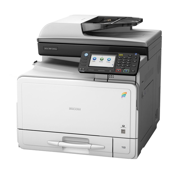
Sign In
Upload
Manuals
Brands
Ricoh Manuals
All in One Printer
D127
Ricoh D127 Manuals
Manuals and User Guides for Ricoh D127. We have
2
Ricoh D127 manuals available for free PDF download: Service Manual, Field Service Manual
Ricoh D127 Service Manual (553 pages)
Brand:
Ricoh
| Category:
All in One Printer
| Size: 4.67 MB
Table of Contents
Legend
5
Table of Contents
5
Important Safety Notices
13
Read this First
13
Laser Safety
14
Lithium Batteries
14
Symbols and Abbreviations
15
Product Information
17
Specifications
19
Product Information
19
Machine Configuration
20
Mainframe
20
System Components
21
Overview
22
Component Layout
22
Mainframe
22
Ardf
23
Electrical Components
24
Electrical Components 1
24
Electrical Components 2
25
Ardf
26
Paper Path
27
Drive Layout
28
Mainframe
28
Ardf
29
Guidance for those Who Are Familiar with Predecessor Products
30
Installation
31
Installation Cautions
33
Installation Requirements
34
Environment
34
Machine Level
34
Minimum Operational Space Requirements
35
Power Requirements
36
Copier
37
Accessory Check
37
Printer/Scanner (D127)/ Scanner and Fax Model (D128)
37
Copier Settings
41
Fax Settings
42
Optional Handset
42
Installation Procedure
43
Accessory Check
44
Installation Procedure
44
Paper Tray Unit (D661)
44
Accessory Check
47
Paper Tray Unit Heater
47
Installation Procedure (for One of Ptu Installed Machine)
49
Installation Procedure (for Two of Ptu Installed Machine)
53
Joint Bracket (Joint the Copier and the Upper Ptu)
59
Joint Bracket (Joint the Upper and the Lower Ptu)
60
Controller Options
61
Overview
61
Accessories
62
Installation Procedure
62
Wireless Lan (Ieee 802.11A/G) Installation
62
Accessories
63
Ieee 1284 Installation
63
SP Mode Settings for IEEE 802.11A/G Wireless LAN
63
Installation Procedure
64
Accessories
65
Installation
65
VM Card Type S (D656)
65
Gigabit Ethernet
66
Component Check
67
Fax Option (D655)
67
Installation Procedure
68
Grounding Wire
69
Component Check
70
Hdd Option (D659)
70
Installation Procedure
71
Installing the Security Card
72
Activating the Security Applications
73
HDD Encryption Recovery from a Device Problem
73
Restoring the Encryption Key
74
Clearing the NVRAM
75
Preventive Maintenance
77
Maintenance Tables
79
How to Clear the Pm Counter
80
Replacement and Adjustment
81
Precautions
83
General
83
Halogen-Free Cable
83
Lithium Batteries
83
Static Electricity
83
Special Tools and Lubricants
84
Exterior Covers and Operation Panel
85
Copy Tray
85
Rear Cover
85
Operation Panel
86
Bypass Tray
87
Right Door
87
Platen Cover and Ardf Sensor
88
Scanner Unit
89
Scanner Cover and Exposure Glass
89
Led Unit
90
Scanner Hp Sensor
91
Scanner Motor
91
Fusing
92
Exit Sensor
92
Fusing Unit
92
Hot Roller Stripper Pawls
93
Hot Roller and Fusing Lamp
94
Thermoswitches and Thermistor
95
Pressure Roller
96
Fusing Nip Band Check By-Pass (Checking the Nip Band)
97
Pcu and Quenching Lamp
98
Pcu
98
Quenching Lamp
99
Exhaust Fan and Main Motor
100
Exhaust Fan
100
Main Motor
101
Paper Feed
103
Paper Feed Roller and Friction Pad
103
Paper End Sensor
104
Registration Sensor
105
Bypass Paper End Sensor
106
Bypass Feed Roller
107
Bypass Feed Clutch and Friction Pad
108
Paper Feed and Registration Clutches
109
Image Transfer
110
Transfer Roller
110
ID Sensor and Duplex Roller
111
Discharge Plate
113
Bicu and Controller Board
114
Bicu
114
Preparation
114
Procedure
114
Controller Board
115
Preparation
115
Procedure
115
When Installing a New Controller Board
117
When Replacing the NVRAM on the Controller Board
118
Other Replacements
119
Duplex Motor
119
High-Voltage Power Supply Board
120
Psu
121
Contact-Release Solenoid
122
Toner Supply Motor
122
Fcu
123
Lithium Batteries
123
Procedure
123
Laser Unit
125
Location of the Caution Decal
125
Laser Unit
126
Ld Unit and Polygon Mirror Motor
127
Ardf
128
Ardf Unit
128
Ardf Rear Cover
129
When Installing the ARDF
129
Original Feed Unit
130
Pick-Up Roller
131
Feed Roller
132
Friction Pad
133
Ardf Top Cover Sensor/ Original Set Sensor
134
Dfrb
134
Ardf Drive Motor
135
When Installing the White Plate
137
White Plate
137
Registration Sensor
138
Adjusting Copy Image Area
139
Adjusting Registration
139
Printing
139
Adjusting Blank Margin
141
Adjusting Main-Scan Magnification
142
Adjusting Registration
142
Scanning
142
Adjusting Magnification
143
Df Image Adjustment
144
System Maintenance Reference
147
Service Program
149
Sp Tables
149
Starting SP Mode
149
Using Sp and Ssp Modes
149
Activating Copy Mode
150
Conventions Used in the Tables
150
Quitting Programs/Ending (S) SP Mode
150
Selecting Programs
150
Specifying Values
150
Using Sp Mode
151
Downloading an SD Card to NVRAM
151
Nvram Data Upload/Download
151
Uploading Content of NVRAM to an SD Card
151
Before You Begin
152
Firmware Update Procedure
152
Firmware Update Procedure
153
Error Messages
154
Firmware Update Error
155
Recovery after Power Loss
155
Browser Unit Update Procedure
156
Error Message Table
157
Handling Firmware Update Errors
157
Executing Test Pattern Printing
159
Test Pattern Print (Sp2-109-001)
159
Test Patterns
159
Memory Clear
160
Exceptions
161
Memory Clear Procedure
161
ID Sensor Error Analysis (Sp2-220)
162
Smc Print (Sp5-990)
162
Fax Service Tables
163
Troubleshooting
165
Sc Tables
167
Engine Sc Code Descriptions
168
Sc Code Descriptions
181
Sc6Xx
181
Sc8Xx
186
Sc9Xx
205
Electrical Component Defects
208
Sensor/Switch
208
Blown Fuse Conditions
210
Card Save Function
211
Card Save
211
Overview
211
Procedure
211
Error Messages
213
Fax Troubleshooting Guide
214
Energy Saving
215
Energy Save
217
Energy Saver Modes
217
Energy Saving
217
Timer Settings
217
Recommendation
218
Paper Save
220
Duplex + Combine:
221
D127/D128
222
D127/D128 Appendices
227
1 Appendix: Specifications
231
Specifications
231
Copier
233
Printer
236
Scanner
237
Fax
238
General
238
IFAX Specifications
239
IP-FAX Specifications
241
Ardf
242
Fax Unit Configuration
242
Paper Tray Unit
243
Supported Paper Sizes
244
Original Paper Sizes
244
Paper Feed
246
Preventive Maintenance Tables
249
2 Appendix: Preventive Maintenance Tables
251
3 Appendix: Sp Mode Tables
255
System Service Mode
257
Service Mode Tables (System Sp Tables)
257
SP1-XXX (Feed)
257
SP2-XXX (Drum)
265
SP4-XXX (Scanner)
280
SP5-XXX (Mode)
297
SP6-XXX (Peripherals)
351
SP7-XXX (Data Log)
354
SP8-XXX (Data Log 2)
363
SP-9XXX (Etc)
396
Conducting Input Check
404
Input Check (Sp5-803)
404
Input Check Table
404
Conducting Output Check
406
Output Check (Sp5-804)
406
Output Check Table
406
Printer Service Mode (Print Sp Tables)
408
Service Mode Table
408
SP Modes Related to Printer Controller
413
Scanner Program Mode Table (Scanner Sp Tables)
414
Service Table Key
414
4 Appendix: Fax Troubleshooting Guide
419
Fax Error Codes
419
Ifax Troubleshooting
439
Ip-Fax Troubleshooting
442
Cannot Send by IP Address/Host Name
442
Ip-Fax Transmission
442
Cannot Send Via Voip Gateway
443
Cannot Send by Alias Fax Number
444
Cannot Receive by IP Address/Host Name
446
Ip-Fax Reception
446
Cannot Receive by Voip Gateway
447
Cannot Receive by Alias Fax Number
448
5 Appendix: Fax Service Program
453
System Service Mode
453
Sp1-XXX (Bit Switches)
453
Sp2-XXX (Ram)
454
Sp3-XXX (Machine Set)
455
Sp4-XXX (Rom Version)
456
Sp5-XXX (Ram Clear)
456
Sp6-XXX (Report)
457
Sp7-XXX (Tests)
459
Bit Switches
460
System Switches
460
I-Fax Switches
473
Printer Switches
481
Communication Switches
488
G3-1 Switches
498
Ip Fax Switches
511
Ncu Parameters
522
Dedicated Transmission Parameters
535
Programming Procedure
535
Fax Parameters
536
Parameters
536
E-Mail Parameters
540
Replacement and Adjustment
548
Paper Tray Unit
548
Feed Roller and Friction Pad
549
Sensors
550
Drive
551
Cooling Fan
551
Drive Bracket and Paper Feed Clutch
552
Paper Feed Motor
552
Tray Main Board
553
Advertisement
Ricoh D127 Field Service Manual (474 pages)
Brand:
Ricoh
| Category:
Copier
| Size: 7.18 MB
Table of Contents
Table of Contents
7
Important Safety Notices
3
Prevention of Physical Injury
3
Health Safety Conditions
3
Observance of Electrical Safety Standards
3
Lithium Batteries
3
Safe and Ecological Disposal
4
Laser Safety
4
Symbols and Abbreviations
6
Table of Contents
7
Product Information
15
Specifications
15
Machine Configuration
16
Mainframe
16
System Components
17
Overview
19
Component Layout
19
Mainframe
19
Ardf
20
Electrical Components 1
21
Electrical Components 2
22
Ardf
23
Paper Path
24
Drive Layout
25
Mainframe
25
Ardf
26
Guidance for those Who Are Familiar with Predecessor Products
27
Installation
29
Installation Cautions
29
Installation Requirements
30
Environment
30
Machine Level
31
Minimum Operational Space Requirements
31
Power Requirements
32
Copier
33
Accessory Check
33
Printer/Scanner (D127)/ Scanner and Fax Model (D128)
33
Installation Procedure
33
Interface Settings
37
Copier Settings
37
Fax Settings
38
Optional Handset
38
Accessory Check
38
Installation Procedure
39
Paper Tray Unit (D661)
41
Accessory Check
41
Installation Procedure
41
Paper Tray Unit Heater
44
Accessory Check
44
Installation Procedure (for One of PTU Installed Machine)
45
Installation Procedure (for Two of PTU Installed Machine)
51
Joint Bracket (Joint the Copier and the Upper PTU)
58
Joint Bracket (Joint the Upper and the Lower PTU)
59
Controller Options
60
Overview
60
Wireless LAN (IEEE 802.11A/G) Installation
60
Accessories
60
Installation Procedure
61
SP Mode Settings for IEEE 802.11A/G Wireless LAN
62
IEEE 1284 Installation
62
Accessories
62
Installation Procedure
63
VM Card Type S (D656)
63
Accessories
63
Installation
64
Gigabit Ethernet
64
Fax Option (D655)
65
Component Check
66
Installation Procedure
67
Grounding Wire
68
HDD Option (D659)
68
Component Check
68
Installation Procedure
69
Installing the Security Card
71
Activating the Security Applications
72
HDD Encryption Recovery from a Device Problem
72
Restoring the Encryption Key
73
Clearing the NVRAM
73
Preventive Maintenance
75
Maintenance Tables
75
How to Clear the PM Counter
76
Replacement and Adjustment
77
Precautions
77
General
77
Lithium Batteries
77
Halogen-Free Cable
77
Static Electricity
78
Special Tools and Lubricants
79
Exterior Covers and Operation Panel
80
Rear Cover
80
Copy Tray
80
Operation Panel
81
Right Door
83
Bypass Tray
83
Platen Cover and ARDF Sensor
84
Scanner Unit
85
Scanner Cover and Exposure Glass
85
LED Unit
85
Scanner Motor
86
Scanner HP Sensor
87
Fusing
88
Fusing Unit
88
Exit Sensor
89
Hot Roller Stripper Pawls
89
Hot Roller and Fusing Lamp
90
Thermoswitches and Thermistor
92
Pressure Roller
93
Fusing NIP Band Check By-Pass (Checking the NIP Band)
94
PCU and Quenching Lamp
95
Pcu
95
Quenching Lamp
96
Exhaust Fan and Main Motor
97
Exhaust Fan
97
Main Motor
97
Paper Feed
99
Paper Feed Roller and Friction Pad
99
Paper End Sensor
100
Registration Sensor
100
Bypass Paper End Sensor
101
Bypass Feed Roller
102
Bypass Feed Clutch and Friction Pad
103
Paper Feed and Registration Clutches
104
Image Transfer
105
Transfer Roller
105
ID Sensor and Duplex Roller
106
Discharge Plate
108
BICU and Controller Board
109
Bicu
109
Preparation
109
Procedure
109
Controller Board
110
Preparation
110
Procedure
110
When Installing a New Controller Board
112
When Replacing the NVRAM on the Controller Board
113
Other Replacements
115
Duplex Motor
115
High-Voltage Power Supply Board
116
Psu
117
Contact-Release Solenoid
118
Toner Supply Motor
118
Fcu
119
Lithium Batteries
119
Procedure
119
Laser Unit
121
Location of the Caution Decal
121
Laser Unit
122
LD Unit and Polygon Mirror Motor
123
Ardf
124
ARDF Unit
124
When Installing the ARDF
125
ARDF Rear Cover
126
Original Feed Unit
126
Pick-Up Roller
127
Feed Roller
127
Friction Pad
129
Dfrb
130
ARDF Top Cover Sensor/ Original Set Sensor
130
ARDF Drive Motor
130
White Plate
133
When Installing the White Plate
134
Registration Sensor
134
Adjusting Copy Image Area
136
Printing
136
Adjusting Registration
136
Adjusting Blank Margin
137
Adjusting Main-Scan Magnification
138
Scanning
138
Adjusting Registration
139
Adjusting Magnification
140
DF Image Adjustment
140
System Maintenance Reference
143
Service Program
143
SP Tables
143
Using SP and SSP Modes
143
Starting SP Mode
144
Selecting Programs
144
Specifying Values
144
Activating Copy Mode
144
Quitting Programs/Ending (S) SP Mode
144
Conventions Used in the Tables
144
Using SP Mode
146
NVRAM Data Upload/Download
146
Uploading Content of NVRAM to an SD Card
146
Downloading an SD Card to NVRAM
146
Firmware Update Procedure
147
Before You Begin
147
Firmware Update Procedure
148
Error Messages
149
Firmware Update Error
149
Recovery after Power Loss
150
Browser Unit Update Procedure
150
Handling Firmware Update Errors
151
Error Message Table
151
Test Pattern Print (SP2-109-001)
152
Executing Test Pattern Printing
152
Test Patterns
153
Memory Clear
154
Exceptions
154
Memory Clear Procedure
155
SMC Print (SP5-990)
155
ID Sensor Error Analysis (SP2-220)
155
Fax Service Tables
157
Troubleshooting
159
SC Tables
159
Summary
159
Engine SC Code Descriptions
160
SC Code Descriptions
171
Sc6Xx
171
Sc8Xx
174
Sc9Xx
189
Electrical Component Defects
192
Sensor/Switch
192
Blown Fuse Conditions
193
Card Save Function
194
Overview
194
Card Save
194
Procedure
194
Error Messages
196
Fax Troubleshooting Guide
197
Energy Saving
199
Energy Save
199
Energy Saver Modes
199
Timer Settings
199
Recommendation
200
Energy Save Effectiveness
200
Paper Save
202
Effectiveness of Duplex/Combine Function
202
Duplex
202
Combine Mode
202
Duplex + Combine
202
Recommendation
203
Table of Contents
209
1 Appendix: Specifications
214
Specifications
215
Printer
215
Scanner
216
Fax
217
General
217
IFAX Specifications
218
IP-FAX Specifications
220
Fax Unit Configuration
220
Ardf
221
Paper Tray Unit
221
Supported Paper Sizes
223
Original Paper Sizes
223
Paper Feed
224
2 Appendix: Preventive Maintenance Tables
227
Maintenance Tables
227
3 Appendix: SP Mode Tables
229
System Service Mode
229
Service Mode Tables (System SP Tables)
229
SP1-XXX (Feed)
229
SP2-XXX (Drum)
235
SP4-XXX (Scanner)
248
SP5-XXX (Mode)
263
SP6-XXX (Peripherals)
311
SP7-XXX (Data Log)
313
SP8-XXX (Data Log 2)
320
SP-9XXX (Etc)
347
Input Check (SP5-803)
353
Conducting Input Check
353
Input Check Table
353
Output Check (SP5-804)
355
Conducting Output Check
355
Output Check Table
355
Printer Service Mode (Print SP Tables)
357
Service Mode Table
357
SP Modes Related to Printer Controller
362
Scanner Program Mode Table (Scanner SP Tables)
362
Service Table Key
362
4 Appendix: Fax Troubleshooting Guide
367
Fax Error Codes
367
IFAX Troubleshooting
386
IP-Fax Troubleshooting
389
IP-Fax Transmission
389
Cannot Send by IP Address/Host Name
389
Cannot Send Via Voip Gateway
390
Cannot Send by Alias Fax Number
390
IP-Fax Reception
392
Cannot Receive by IP Address/Host Name
392
Cannot Receive by Voip Gateway
392
Cannot Receive by Alias Fax Number
393
5 Appendix: Fax Service Program
395
System Service Mode
395
SP1-XXX (Bit Switches)
395
Sp2-XXX (Ram)
396
SP3-XXX (Machine Set)
396
SP4-XXX (ROM Version)
397
SP5-XXX (RAM Clear)
397
SP6-XXX (Report)
398
SP7-XXX (Tests)
400
Bit Switches
401
System Switches
401
I-Fax Switches
412
Printer Switches
420
Communication Switches
425
G3-1 Switches
433
Ip Fax Switches
444
Ncu Parameters
453
Dedicated Transmission Parameters
467
Programming Procedure
467
Advertisement
Related Products
Ricoh D129
Ricoh D128
Ricoh D124-17
Ricoh D124-21
Ricoh D124-27
Ricoh D129-17
Ricoh D129-57
Ricoh D159
Ricoh D106
Ricoh D130
Ricoh Categories
All in One Printer
Printer
Digital Camera
Copier
Printer Accessories
More Ricoh Manuals
Login
Sign In
OR
Sign in with Facebook
Sign in with Google
Upload manual
Upload from disk
Upload from URL