Sign In
Upload
Manuals
Brands
Radionics Manuals
Cell Phone
D9412G
Radionics D9412G Manuals
Manuals and User Guides for Radionics D9412G. We have
1
Radionics D9412G manual available for free PDF download: Operation And Installation Manual
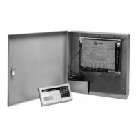
Radionics D9412G Operation And Installation Manual (76 pages)
Control/Communicators
Brand:
Radionics
| Category:
Cell Phone
| Size: 11.06 MB
Table of Contents
Table of Contents
3
Table 1: D9412G/D7412G Operation and Installation Guide Organization
9
Documentation Conventions
10
Related Documentation
10
Type Styles Used in the Text
10
1 Introduction
9
Manual Organization
9
Table 2: Related Documentation
10
FCC Rules
11
Part 15
11
Part 68
11
Tips, Notes, Cautions and Warnings
11
Table 3: Differences between the D9412G and D7412G
13
Figure 1: System Configuration
13
Specifications
14
2 Overview
13
D9412G/D7412G Differences
13
Table 4: Specifications
14
Table 5: Compatible Command Centers
17
Available by Separate Order
18
Control/Communicator Assembly
18
EMI & Lightning Transient Protection
18
Other Features
18
Programming
18
Listings and Approvals
19
Added Feature When Using Ground Fault Detect
16
Areas and Accounts
16
Communicator
16
Ground Fault Detect
16
Introduction
16
Netcom Functionality
16
New Features in D9412G/D7412G
16
Points
16
Standard Features
16
Access Control
17
Command Centers
17
Event Log
17
Event Memory
17
Keyswitch
17
Table 6: Listings
19
Figure 2: Enclosure Mounting
21
Connecting Earth Ground
22
Ground Fault Detect Enable
22
Installing the Assembly
22
Locking the Reset Pin
22
Terminal
22
3 Installation
21
Before Beginning
21
Beginning the Installation
21
Enclosure Options
21
Figure 4: Reset Pin
22
Figure 3: Ground Fault Detect
22
Charge the Battery While Finishing
23
Connect the On-Board Points and Command Centers
23
Finishing the Installation
23
Install and Wire Detection Devices
23
Install Modules and Relays
23
Make the Telephone Connections
23
Install the Point Chart Label
24
Power up
24
Programming the Panel
24
Testing the System
24
4 Power Supply
25
Installing the Battery
25
Installing the Transformer
25
Primary (AC) Power Circuit
25
Primary Power Terminals
25
Secondary (DC) Power
25
Secondary Power Terminals
25
Figure 5: Non Power Limited Wiring
26
Replacing the Battery
26
Battery Charging Circuit
27
Battery Supervision
27
Battery Discharge/Recharge Schedule
28
Charging Status and Low Battery Leds
28
Figure 6: Charging and Battery Leds
28
Table 7: Charging Status and Low Battery Leds
28
5 Power Outputs
29
Circuit Protection
29
Continuous Current Draw
29
Continuous Power Outputs Terminals
29
Programmable Power Outputs Terminals
29
Programming
29
Total Available Power
29
Figure 7: Relays for Terminals 7 and 8 and Ground Start
30
Fire System Power Formula
30
Optional Relays Required
30
Terminals 6 and 7
30
Terminal 8
31
Figure 9: Phone Connector and LED and Operation Monitor LED Locations
33
Figure 8: RJ31X Wiring
33
Called Party Disconnect
34
Communication Failure
34
Dialing Format
34
Enhanced Communication
34
Operation Monitor LED (Green)
34
Phone Line Monitor
34
D928 Dual Phone Line Switcher
35
Description
35
Ground Start
35
Operation
35
Phone Monitor Select Jumper
35
Relay Installation
35
6 Telephone Connections
33
Location
33
Notification
33
Phone Cord Connection
33
Phone LED (Red)
33
Registration
33
Figure 10: Phone Monitor Select
35
D928 Status Leds
36
Installing the D928
36
Watchdog Feature
36
Figure 11: D928 Dual Phone Line Switcher
36
7 On-Board Points
37
Description Terminals
37
Figure 12: On-Board Point Sensor Loop Wiring
37
Point Parameters
37
Point Response Time
37
Point Sensor Loops
37
Wiring Information for Installations Using the Ademco AB-12 Bell/Housing
38
Figure 13: Wiring for Installations Using the Ademco AB-12 Bell/Housing
38
8 Off-Board Points
39
D8125, D8127 and D9127 POPIT Modules
39
Listings
39
Point (ZONEX) Bus D9412G Terminals D7412G Terminals
39
Figure 14A: Connecting the D8125 POPEX to the D9412G Panel
40
Figure 14B: Connecting the D8125 POPEX to the D7412G Panel
41
Table 8: Data Expansion Loop Wire Specifications
42
Figure 15: Program Record Sheet
44
Installing the Octopopit
45
Line Termination
45
Wiring Octopopits
45
Address Assignment Switches
46
Octopopit Sensor Loops
46
Testing Off-Board Points
46
POPIT Module Point Assignments
43
POPIT Sensor Loops
43
Program Record Sheet
43
Wiring Data Expansion Loops to POPEX Modules
43
D8128D Octopopit Module
44
Description
44
Listing
44
Installing the D8125 POPEX Module
42
Mounting
42
Wiring Popits to the Data Expansion Loop
42
Wiring the D8125 to the Control/Communicator
42
Table 9: D8128D Octopopit Switch Settings for D9412G/D7412G
46
Figure 16A: Connecting D8128D Octopopits to the D9412G
47
Figure 16B: Connecting D8128D Octopopits to the D7412G
48
Table 10: D8129 Octorelay Switch Settings
49
9 Off-Board Relays
49
Configuring the D8129 Octorelay
49
D8129 Octorelay
49
Installation
49
Relay Outputs
49
Wiring Connections
49
Table 11: Number of D8128Ds Used with D8129S
50
Figure 17B: D8129 Connections to the D7412G
50
Figure 17A: D8129 Connections to the D9412G
50
D811 Arm Status Relay Module
51
Figure 18A: D811 Module Wiring to the D9412G
51
Installation
51
Relay Output
51
Wiring Connections
51
Figure 18B: D811 Module Wiring to the D7412G
52
Table 13: Command Center Connections
53
Table 12: Command Center Address Settings
53
D268/D269 Independent Zone Control, D279A Independent Zone Control
54
10 Arming Devices
53
Assigning the Command Center an Address
53
Command Center Terminals
53
Description
53
Installation
53
Figure 19: Power at Command Centers
54
Description
55
Installation
55
Keyswitch
55
Keyswitch Operation
55
Programming
55
Figure 20: Keyswitch Wiring
55
11 SDI Devices
57
D9131A Parallel Printer Interface Module
57
Description
57
Installation
57
Supervision
57
Switch Settings
57
Table 15: Printer Address Switch Settings
57
Table 16: Access Control Module Address Switch Settings
58
Address Settings
59
Connecting the D9133DC
59
D9133DC Direct Connect Programming Module
59
D9133TTL-E Network Interface Module
59
SDI Address 88
59
Supervision
59
Used as an External Modem
59
Table 14: SDI Device Connections
57
Address Settings
58
D9133 Serial Interface Module
58
D9210B Wiegand TM Control Interface Module
58
SDI Address 80
58
Supervision
58
Switch Settings
58
Figure 21: Reset Pin
61
12 Programmer and Accessory Connections
61
Accessory Connector
61
Figure 22: Programmer and Accessory Connections
61
Programmer Access Reports
61
Programmer Connector
61
Figure 23A: D9412G Faceplate
63
D7412G Faceplate
64
13 Faceplates
63
D9412G Faceplate
63
Figure 23B: D7412G Faceplate
64
Figure 24A: D9412G System Wiring Diagram, 1 of 3
65
Appendix A: System Wiring Diagrams, Issue a
65
D9412G Control/Communicator, 1 of 3
65
Figure 24B: D9412G System Wiring Diagram, 2 of 3
66
D9412G Control/Communicator, 2 of 3
66
Figure 24C: D9412G System Wiring Diagram, 3 of 3
67
D9412G Control/Communicator, 3 of 3
67
Figure 25A: D7412G System Wiring Diagram, 1 of 3
68
D7412G Control/Communicator, 1 of 3
68
Figure 25B: D7412G System Wiring Diagram, 2 of 3
69
D7412G Control/Communicator, 2 of 3
69
D7412G Control/Communicator, 1 of 3
69
Figure 25C: D7412G System Wiring Diagram, 3 of 3
70
Table 17: ZONEX 1 Point Address Chart
71
Appendix B: Point Address Charts
71
ZONEX 1, Points 9 to 127 (D9412G); ZONEX 1, Points 9 to 75 (D7412G)
71
Table 18: ZONEX 2 Point Address Chart
72
ZONEX 2, Points 129 to 247 (D9412G Only)
72
Advertisement
Advertisement
Related Products
Radionics D2112E
Radionics D7412G
Radionics D9412
Radionics D9024
Radionics D9124
Radionics D9000 Series
Radionics D9112
Radionics D9210B
Radionics D2812
Radionics D10024
Radionics Categories
Security System
Control Panel
Keypad
Control Systems
Fire Alarms
More Radionics Manuals
Login
Sign In
OR
Sign in with Facebook
Sign in with Google
Upload manual
Upload from disk
Upload from URL