Sign In
Upload
Manuals
Brands
Perlick Manuals
Refrigerator
CR24F-1-2R
Perlick CR24F-1-2R Manuals
Manuals and User Guides for Perlick CR24F-1-2R. We have
2
Perlick CR24F-1-2R manuals available for free PDF download: Service Manual, Installation Instructions Manual
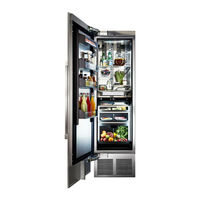
Perlick CR24F-1-2R Service Manual (133 pages)
Column Refrigeration
Brand:
Perlick
| Category:
Refrigerator
| Size: 14 MB
Table of Contents
Table of Contents
6
Figure 1-1. Information Plate for Refrigeration Units
10
Figure 2-1.1. Danger Fire/Explosion Risk Label
12
Figure 2-1.2. Danger Fire/Explosion Risk Servicing Label
12
Figure 2-1.3. Warning Handling Label
12
Figure 2-1.4. Warning Tip-Over Hazard Label
12
Figure 2-1.5. Disposal Label
12
Figure 2-1.6. Warning Transporting Hazard Label
12
Figure 2-1.7. Uncrating Label
12
Table 3.1. Refrigeration System Diagnostics/Troubleshooting
13
Table 3.2. Electrical System Diagnostics/Troubleshooting
17
Table 3.3. Doors,Drawers,Shelving Diagnostics/Troubleshooting
19
Table 4.1.1. Compressor Specs (Model VEMX5C)
20
Table 4.1.2. Compressor Specs (Model VEMV9C)
20
Table 4.2.1. Inverter Specs (Drop-In)
20
Table 4.2.2. Inverter Specs (Frequency Drive)
20
Table 4.3. Condenser Fan Motor Specs
20
Table 4.4. Evaporator Fan Motor Specs
20
Table 4.5. Hot Gas Defrost Solenoid Valve Specs
21
Table 4.6. Control Specs
21
Table 4.7. Damper Specs
21
Table 5.1.1. Modes of Operation (CR24R and CR30R)
22
Table 5.1.2. Modes of Operation (CR24F)
23
Table 5.1.3. Modes of Operation (CR24W/CC24W)
24
Table 5.1.4. Modes of Operation (CR24D/CC24D)
25
Table 5.2. Electrical Specifications
26
Figure 5-1.1. Column Refrigerator Wiring Diagram
27
Figure 5-1.2. Wine Column Single Zone Wiring Diagram
28
Figure 5-1.3. Wine Column Dual-Zone Wiring Diagram
29
Figure 5-1.4. Column Freezer Wiring Diagram
30
Table 5.3. Control Alarms
31
Table 5.4. Low/High Temperature Alarm Offsets
31
Figure 5-2. Refrigerator Touch Screen Control
32
Figure 5-3. Freezer Touch Screen Control
37
Figure 5-4. Wine Reserve Touch Screen Control
40
Table 5.5. Ambient Conditions (Wine Reserve)
43
Figure 6-1.1. Sealing Compound (Inside)
44
Figure 6-1.2. Sealing Compound (Outside)
44
Figure 6-1.3. Sealing Compound - Door Switch (Inside)
44
Figure 6-1.4. Sealing Compound - Door Switch (Outside)
44
Figure 6-2.1. Refrigerator Gasket
45
Figure 6-2.2. Lift Bolts
45
Figure 6-3. Evaporator Condensate Drain
45
Figure 6-4.1. Grill/Toe Kick Inlet and Outlet
46
Figure 6-4.2. Evaporator Intake Openings
46
Table 6.1. Ambient Conditions (Freezer)
46
Figure 6-5.1. Evaporator Air Outlet Louvers
47
Figure 6-5.2. Evaporator Air Damper Outlet Openings
47
Figure 6-6. Condenser Airflow Divider
47
Figure 6-7.1. Remove Grill
48
Figure 6-7.2. Clean Condenser Coil
48
Figure 6-8. Freezer Drawer
49
Figure 6-9.1. Wine Shelves
49
Figure 6-9.2. Bottom Shelves/Bottom Panel
49
Figure 6-10. Tip-Out Bin/Inner Liner
49
Figure 6-11. Evaporator Coil
49
Figure 6-12.1. Remove Grill
50
Figure 6-12.2. Remove Lift Bracket
50
Figure 6-12.3. Disconnect Refrigeration Wiring
50
Figure 6-12.4. Lower Refrigeration Module
51
Figure 6-12.5. Slide Refrigeration Module out
51
Figure 6-12.6. Disconnect Power Cord
51
Figure 6-12.7. Slide Unit Back into Cabinet
52
Figure 6-12.8. Reinstall Front Lift Bracket
52
Figure 6-13. Condenser Fan Motor/Fastener
53
Figure 6-14.1. Evaporator Fan Motor/Fastener
53
Figure 6-14.2. Evaporator Terminal Block
53
Figure 6-15.1. Remove Cotter Pins
54
Figure 6-15.2. Lift and Rotate Compressor
54
Figure 6-15.3. Inverter Mounting Screw/Electrical Connections
55
Figure 6-15.4. Lift Inverter
55
Figure 6-15.5. Remove 3-Pin and Ground Connectors
56
Figure 6-15.6. Install Inverter and Remount Compressor
56
Figure 6-15.7. Connect Inverter Wires
57
Figure 6-15.8. Feed Harness End through Access Hole
57
Figure 6-15.9. Seal Access Hole
58
Figure 6-15.10. Connect New Harness
58
Figure 6-16.1. Refrigerator and Dual-Zone Wine Lower Damper
59
Figure 6-16.2. Dual-Zone Wine Upper Damper
59
Figure 6-16.3. Dual-Zone Wine Upper Damper (Cover and Insulation Pad Suppressed)
59
Figure 6-16.4. Damper Electrical Connection
59
Figure 6-17.1. Refrigeration System Diagram (Medium Temperature)
61
Figure 6-17.2. Refrigeration System Diagram (Freezer)
62
Table 7.1. LED Diagnostics
63
Table 7.2. LED Troubleshooting
63
Figure 7-1. Visible LED Descriptions
64
Figure 7-2.1. Remove Wine Shelving
66
Figure 7-2.2. Pry Light Covering
67
Figure 7-2.3. Pry Light Housing Board
67
Figure 7-2.4. Disconnect Board from Harness
68
Figure 7-2.5. Remove Wine Shelving
68
Figure 7-2.6. Remove Carbon Filter
69
Figure 7-2.7. Remove Wire Harness Cover
69
Figure 7-2.8. Remove Controller Cover
70
Figure 7-2.9. Disconnect Light Harness
70
Table 7.3. Column Temperature/Humidity Sensors
71
Table 7.4. Temperature - Resistance Values
71
Figure 7-3.1. Evaporator Temperature Probe
72
Figure 7-3.2. Dual-Zone Wine Lower Compartment Temperature/Humidity Sensor
72
Figure 7-3.3. Dual-Zone Upper and Single-Zone Temperature/Humidity Sensor
72
Figure 7-3.4. Freezer and Refrigerator (Main Compartment) Temperature Probe
72
Figure 7-3.5. Refrigerator Deli bin Temperature Probe
72
Figure 7-3.6. Refrigerator Meat/Fish bin Temperature Probe
72
Figure 7-3.7. Refrigerator Tip-Out bin Temp/Humidity Sensor
72
Figure 7-4. Door Magnet (Reed Switch)
73
Figure 8-1. Overlay Panel Installation
74
Figure 8-2. Top of Door Illustration
75
Figure 8-3. Door Trim Installation
76
Figure 8-4. Grill Installation
77
Figure 8-5. Toe Kick Clearance
78
Figure 8-6. Air Filter Installation
79
Figure 8-7.1. Hinge Activation Fastener (De-Activated)
80
Figure 8-7.2. Hinge Activation Fastener (T-20) (Activated)
80
Figure 8-8. Removing Gasket
81
Figure 8-9. Removing Door Trim Cover
82
Figure 8-10. Lock Installation
83
Table 8.1. Lock Troubleshooting
83
Figure 8-11.1. CR24 Solid Door Template for 4" Toe Kick
85
Figure 8-11.2. CR30R Solid Door Template for 4" Toe Kick
86
Figure 8-11.3. CR24 Solid Door Template for 6" Toe Kick
87
Figure 8-11.4. CR30 Solid Door Template for 6" Toe Kick
88
Figure 8-11.5. CR24 Glass Door Template for 4" Toe Kick
89
Figure 8-11.6. CR24 Glass Door Template for 6" Toe Kick
90
Figure 8-12.1. CR24 Screw Zone for Overlay Templates
91
Figure 8-12.2. CR30 Screw Zone for Overlay Templates
92
Figure 8-13.1. - 8-13.4. Refrigerator Tip-Out bin Removal
93
Figure 8-14 - Deli and Meat Drawer Release
100
Figure 8-15.1 - Freezer Drawer Slide
101
Figure 8-15.2 - Freezer Drawer Release
101
Figure 8-16 - Drawer Compartment Divider and Retaining Pin
102
Figure 8-17.1. & 8-17.2. Remove Wine Shelves
103
Figure 8-17.3. & 8-17.4. Install Wine Shelves
103
Figure 8-18. Freezer Shelving
104
Figure 8-19. Refrigerator Shelving
105
Figure 8-20.1. & 8-20.2. Dual-Zone Compartment Divider
106
Figure 8-21. Leveling/Alignment
107
Figure 8-22.1. Anti-Tip Installation (Integrated)
109
Figure 8-22.2. Anti-Tip Installation (Freestanding)
110
Figure 8-23.1. - 8-23.4. Marriage Kit Install
111
Figure 8-24.1. Butter bin
115
Figure 8-25. Trim Kit
116
Figure 9-1. CR24R, CR24D, CR24W, CC24D, CC24W, and CR30R Refrigeration Module
117
Figure 9-2. CR24F Refrigeration Module
118
Figure 9-3. CR24F Drawers
119
Figure 9-4. CR24R Shelving
120
Figure 9-5. CR30R Shelving
121
Figure 9-6. CR24R, CR24F, and CR30R Door
122
Figure 9-7. CR24R and CR30R Drawers
123
Figure 9-8. Damper Tip-Out bin
124
Figure 9-9. CR24R, CR24D, CR24W, CR24F, CC24D, CC24W, and CR30R Machine Compartment
125
Figure 9-10. CR24D, CR24W, CC24D and CC24W Shelving
126
Figure 9-11. CR24D, CR24W, CC24D and CC24W Door
127
Figure 9-12. CR24F - Column Freezer
128
Figure 9-13. CR24R - Column Refrigerator
129
Figure 9-14. CR24D & CC24D - Dual-Zone Wine Column
130
Figure 9-15. CR24W & CC24W - Single-Zone Wine Column
131
Figure 9-16. CR24W & CC24W - Single-Zone Wine Column Shelves
132
Advertisement
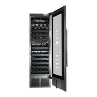
Perlick CR24F-1-2R Installation Instructions Manual (22 pages)
PERLICK COLLECTION 24” COLUMN REFRIGERATION
Brand:
Perlick
| Category:
Refrigerator
| Size: 1 MB
Table of Contents
Table of Contents
2
Safety Considerations
3
Prior to Installation
4
Opening Dimensions (Single and Dual)
4
Niche/Product Dimensions
5
Electrical
6
Anti-Tip Bracket
6
Leveling/Alignment
7
Door/Side Panel Information
10
Door Panel Installation/Adjustment
16
Door Trim Installation
18
Completion - Grill Installation
19
Toe Kick Clearance
20
Installing Filters
21
Advertisement
Related Products
Perlick CR24F
Perlick CR24F12L
Perlick CR24
Perlick CR24D
Perlick CR24W
Perlick CR24R
Perlick CR24R12R
Perlick CR24R12
Perlick CR24D14R
Perlick CR24W14L
Perlick Categories
Refrigerator
Commercial Food Equipment
Ice Maker
Kitchen Appliances
Beverage Dispenser
More Perlick Manuals
Login
Sign In
OR
Sign in with Facebook
Sign in with Google
Upload manual
Upload from disk
Upload from URL