Sign In
Upload
Manuals
Brands
Omron Manuals
Inverter
SYSDRIVE 3G3JX-A4037
Omron SYSDRIVE 3G3JX-A4037 Manuals
Manuals and User Guides for Omron SYSDRIVE 3G3JX-A4037. We have
3
Omron SYSDRIVE 3G3JX-A4037 manuals available for free PDF download: User Manual, Replacing Manual, Instruction Manual
Omron SYSDRIVE 3G3JX-A4037 User Manual (263 pages)
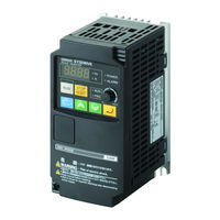
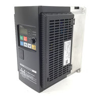
SYSDRIVE JX SERIES Compact Simplified Inverters
Brand:
Omron
| Category:
Inverter
| Size: 3.62 MB
Table of Contents
Application Considerations
5
Dimensions and Weights
6
Alert Symbols in this Document
7
Safety Precautions
7
Precautions for Safe Use
9
Safe Installation and Storage
9
Safe Transporting, Installation, and Wiring
9
Precautions for Correct Use
10
Warning Labels
11
Checking before Unpacking
12
Checking the Accessories
12
Checking the Model
12
Checking the Nameplate
12
Revision History
13
About this Manual
14
Table of Contents
15
Chapter 1 Overview
17
Functions
18
Appearance and Names of Parts
20
Product View
20
Connection to RJ45 Jack
20
Names of Parts Inside the Front Cover
21
Chapter 2 Design
23
Installation
24
Safety Information
24
Precautions for Use
25
Main Circuit Power Supply
26
Installation Environment
26
Wiring
29
Removing and Mounting the Front Cover
29
Standard Connection Diagram
31
Wiring to the Power Supply and Motor
32
Wiring the Control Circuit Terminals and Relay Terminals
33
Wiring Example of the Control Circuit Terminal Block (Sink Logic)
34
Selecting the Sequence Input Method (Sink/Source Logic)
35
Logic Selection Method for the Multi-Function Input Terminal
35
Wiring the Main Circuit Terminals
36
Terminal Arrangement
37
Explanation of the Main Circuit Terminal Connection
38
Main Circuit Connection Diagram
39
Wiring the Main Circuit Terminals (Input Side)
39
Installing a Molded-Case Circuit Breaker (MCCB)
39
Installing a Ground Fault Interrupter
39
Installing a Magnetic Contactor (MC)
40
Installing an AC Reactor
40
Connecting a Regenerative Braking Unit
40
Connection Sequence to the Terminal Block
40
Installing a Noise Filter on the Input Side
41
Wiring the Main Circuit Terminals (Output Side)
42
Connect the Terminal Block to the Load
42
Install a Noise Filter on the Output Side
43
Countermeasures against Induction Noise
43
Cable Length between Inverter and Motor
44
Do Not Use Single-Phase Motors
44
Specifications of the Control Circuit Terminals
45
Functions and Connections of the Control Circuit Terminals
46
Mode Selector
47
RS-485 Communication/Operator Selector
47
Emergency Shutoff Selector
47
Conforming to Ec Directives
48
Chapter 3 Operation
49
Error Retry Function
50
Non-Stop Function at Momentary Power Interruption
50
Operation and Adjustment
50
Operation Stop Command
51
Test Run Procedure
52
Test Run Operation
53
Power on
53
Display Status Check
53
Checkpoints before Turning on the Power
53
Parameter Initialization
54
Setting the Motor Capacity Selection and Motor Pole Number Selection
55
No-Load Operation
56
Forward/Reverse Rotation Via the Digital Operator
56
Actual Load Operation
56
Connecting the Mechanical System
56
Checking the Operating Status
57
Part Names and Descriptions of the Digital Operator
58
Operation Procedure (Example: Factory Default)
60
Displaying Monitor Mode, Basic Function Mode, Extended Function Mode
60
Setting Functions
62
Setting Function Codes
63
Keys
66
Parameter Transition
67
Parameter List
69
Monitor Mode / Basic Function Mode
69
Extended Function Mode
70
Chapter 4 Functions
85
Monitor Mode
86
Output Frequency Monitor
86
Output Current Monitor
86
Rotation Direction Monitor/Pid Feedback Value Monitor
86
Multi-Function Input Monitor
87
Multi-Function Output Monitor
87
Output Frequency Monitor (after Conversion)
87
Output Voltage Monitor
88
Total RUN Time
88
Power on Time Monitor
88
Fin Temperature Monitor/Fault Frequency Monitor
88
Fault Monitors
89
DC Voltage Monitor
89
Electronic Thermal Monitor
89
Function Mode
90
Group F: Basic Function Parameter
90
Output Frequency Setting/Monitor
90
Acceleration/Deceleration Time
90
Digital Operator Rotation Direction Selection
91
Group A: Standard Function Parameter
92
Frequency Reference Selection
92
RUN Command Selection
92
Base Frequency
93
Maximum Frequency
93
Analog Input (FV, FI)
94
External Frequency (Voltage/Current) Adjustment
95
FV, FI Sampling
96
Multi-Step Speed Operation Function
96
Jogging Operation Function
97
Relation between Torque Boost and V/F Characteristics
97
Control Method (V/F Characteristics)
98
Constant Torque Characteristics (VC)
98
Reduced Torque Characteristics (VP 1.7Th Power)
98
Special Reduced Torque Characteristics (Special VP)
98
Torque Boost
99
Output Voltage Gain
99
DC Injection Braking (DB)
100
External DC Injection Braking
100
Internal DC Injection Braking
102
Frequency Limit
104
Frequency Jump Function
104
PID Function
105
Basic Structure of PID Control
105
PID Operation
106
Target Value Selection
106
PID Feedback Value Monitor
106
Excessive Deviation/Output
106
PID Gain Adjustment
107
PID Integral Reset
107
PID Comparison Function
107
AVR Function
108
Automatic Energy-Saving Operation Function
108
2-Step Acceleration/Deceleration Function
109
Acceleration/Deceleration Pattern
110
External Frequency Adjustment Function (FI)
110
Operation Frequency Function
111
Frequency Addition Function
111
Group B: Detailed Function Parameter
112
Momentary Power Interruption/Trip Retry (Restart)
112
VR Adjustment Function
112
Trip Retry Function
113
Electronic Thermal Function
114
Alarm Selection for Momentary Power Interruption During Stop
114
Electronic Thermal Level (Motor Protection Level)
115
Electronic Thermal Characteristics
115
Overload Limit/Overload Warning
116
Overload Warning
117
Soft Lock Function
118
Momentary Power Interruption Non-Stop Function
118
Overvoltage Control Function During Deceleration
120
AM Adjustment
120
Starting Frequency
121
Carrier Frequency
121
Frequency Conversion Coefficient
124
STOP Key Selection
124
Free-Run Stop Selection and Stop Selection
124
Main Unit Monitor Display Selection
125
Cooling Fan Control
125
Overvoltage LAD Stop Function
126
Overcurrent Suppression Function
127
Automatic Carrier Frequency Reduction Function
127
RDY (Ready) Function
127
Group C: Multi-Function Terminal Function
128
Multi-Function Input Selection
128
Emergency Shutoff Input Function
130
Emergency Shutoff Mode Selection
130
Wiring Example
130
Jogging Operation
133
Jogging Frequency
134
Jogging Stop Selection
134
2Nd Control Function and Special 2Nd Function
136
Free-Run Stop
138
External Trip
139
Power Recovery Restart Prevention Function
140
AT Input Function
141
Reset
141
Thermistor Trip Function
142
3-Wire Input Function
143
PID Enable/Disable and PID Integral Reset
144
UP/DOWN Function
144
Forced Operator Function
145
Forced Terminal Block Function
146
Ready Function
147
Multi-Function Output Terminal Selection
147
Signal During RUN
148
Frequency Arrival Signal
148
Constant Speed Arrival Output
149
Output over Set Frequency
149
Overload Warning Signal
150
Excessive PID Deviation Output
150
Alarm Output
151
External Analog Input Disconnection Detection
151
PID FB Status Output
152
Network Error
153
Logic Operation Result Output
154
Light Load Detection Signal
155
Multi-Function Output Terminal on Delay/Off Delay
155
Multi-Function Output Terminal Contact Selection
156
Specifications of the Multi-Function Output Terminal
156
Specifications of the Relay Output Terminals
157
Analog Input
158
Using the External Volume (VR)
158
Inputting the Voltage
158
Inputting the Current
158
FV/FI Adjustment
159
Analog Output am Terminal
160
AM Selection
160
Group H: Motor Control Parameters
161
Motor Capacity and Pole Number
161
Stabilization Parameter
161
Communication Function
162
RS-485 Port Specifications and Connection
162
Communication Specifications
162
Modbus Setting
163
Switching from the External OPE to Modubus
163
Switching from Modubus to the External OPE
163
Modbus-Related Parameter Settings
164
Modbus Communication-Related Parameter List
164
Modbus Communication Protocol
165
Message Configuration: Response
167
Total Communication Time
167
Normal Response
167
Abnormal Response
167
Explanation of each Function Code
168
No Response
168
Writing into the Coil
171
Writing into the Holding Register
171
Writing into Multiple Coils
173
To Save the Change to the Holding Register (Enter Command)
175
Register Number List
176
Holding Register Number List
177
Chapter 5 Maintenance Operations
191
Special Display List
192
Error Code List
192
Other Displays
194
Trip Monitor Display
195
Troubleshooting
196
Chapter 6 Inspection and Maintenance
199
General Precautions
201
Inspection Item
201
Daily Inspection and Periodic Inspection
202
Measurement Methods of I/O Voltage, Current, and Electric Power
204
Storage
206
Chapter 7 Specifications
208
Standard Specification List
208
Common Specifications
210
Measurement Method of Output Voltage
212
Connection Example
213
Dimensional Drawing
215
Options
221
Regenerative Braking Unit
221
DC Reactor
224
Operating Environment
225
Input Noise Filter
226
EMC-Compatible Noise Filter
228
Output Noise Filter
234
AC Reactor
235
Digital Operator
237
Appendix
239
Appendix-1 Parameter List
240
Appendix-2 Product Life Curve
256
Index
257
Index
258
Advertisement
Omron SYSDRIVE 3G3JX-A4037 Replacing Manual (32 pages)
Simple, Compact Inverters
Brand:
Omron
| Category:
Inverter
| Size: 1.05 MB
Table of Contents
Introduction
3
Intended Audience
3
Applicable Products
3
Terms and Conditions Agreement
4
Precautions
6
Related Manuals
7
Revision History
8
Table of Contents
9
Target Model
10
Precautions for Replacement
11
External Dimensions and Mounting Dimensions
12
External Dimensions
12
External Dimensions
13
Arrangement and Function of Terminal Block
17
Control Circuit Terminal Block
17
Functional Difference
19
Dual Duty Rating
19
Modbus Communication
19
Parameter List
20
The Difference of Parameter Arrangement, Parameter Name and Default Value
20
The Difference of Multi-Function Input Settings
21
The Difference of Multi-Function Output Settings
22
Modbus Communication Data Correspondence List
23
Coil Number
23
Register Number
24
Omron SYSDRIVE 3G3JX-A4037 Instruction Manual (4 pages)
3G3JX-A Series SYSDRIVE Inverter
Brand:
Omron
| Category:
Inverter
| Size: 0.74 MB
Advertisement
Advertisement
Related Products
Omron SYSDRIVE 3G3JX-A4004
Omron SYSDRIVE 3G3JX-A4007
Omron SYSDRIVE 3G3JX-A4015
Omron SYSDRIVE 3G3JX-A4022
Omron SYSDRIVE 3G3JX-A4055
Omron SYSDRIVE 3G3JX-A4075
Omron SYSDRIVE 3G3JX-AE007
Omron SYSDRIVE 3G3JX-AE015
Omron 3G3JX-AE015-V1
Omron SYSDRIVE 3G3JX-A2022
Omron Categories
Blood Pressure Monitor
Controller
Accessories
Switch
Inverter
More Omron Manuals
Login
Sign In
OR
Sign in with Facebook
Sign in with Google
Upload manual
Upload from disk
Upload from URL