Sign In
Upload
Manuals
Brands
OMRON Manuals
I/O Systems
CXONE-ALD-V4 - 10-2010
OMRON CXONE-ALD-V4 - 10-2010 Manuals
Manuals and User Guides for OMRON CXONE-ALD-V4 - 10-2010. We have
3
OMRON CXONE-ALD-V4 - 10-2010 manuals available for free PDF download: User Manual, Operation Manual
Omron CXONE-ALD-V4 - 10-2010 User Manual (424 pages)
Machine Automation Controller
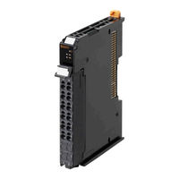
 NX-series Digital I/O Units
Brand:
Omron
| Category:
I/O Systems
| Size: 11 MB
Table of Contents
Introduction
3
Intended Audience
3
Applicable Products
3
Table of Contents
4
Relevant Manuals
9
Manual Structure
10
Page Structure and Icons
10
Special Information
11
Precaution on Terminology
12
Terms and Conditions Agreement
13
Warranty, Limitations of Liability
13
Application Considerations
14
Disclaimers
14
Safety Precautions
15
Definition of Precautionary Information
15
Symbols
15
Warnings
16
Cautions
17
Precautions for Safe Use
19
Precautions for Correct Use
24
Regulations and Standards
25
Conformance to EU Directives
25
Conformance to UL and CSA Standards
26
Conformance to Shipbuilding Standards
26
Conformance to KC Standards
26
Software Licenses and Copyrights
26
Unit Versions
27
Unit Versions and Support Software Versions
28
Related Manuals
29
Terminology
32
Revision History
34
Sections in this Manual
35
Features and System Configuration
37
Features and Types of Digital I/O Units
38
Digital I/O Unit Features
38
Digital I/O Unit Types
39
System Configuration
40
System Configuration in the Case of a CPU Unit
40
System Configuration of Slave Terminals
41
Model List
43
Model Notation
43
Digital Input Units
44
Digital Output Units
44
Digital Input Units
46
Digital Output Units
48
Digital Mixed I/O Units
51
List of Functions
52
Digital Input Units
52
Digital Output Units
53
Digital Mixed I/O Units
54
Support Software
55
Specifications
57
Section 2 Specifications
58
General Specifications
58
Individual Specifications
59
Part Names and Functions
61
Part Names
62
Screwless Clamping Terminal Block Type
62
M3 Screw Terminal Block Type
67
Connector Types
68
Indicators
73
TS Indicator
75
IN/OUT Indicator
76
Installation and Wiring
77
Section 4 Installation and Wiring
78
Installing NX Units
78
Attaching Markers
80
Removing NX Units
82
Installation Orientation
83
Power Supply Types and Wiring
85
Applications of I/O Power Supply and Supply Methods
85
Calculating the Total Current Consumption from I/O Power Supply
87
Wiring the Terminals
88
Wiring to the Screwless Clamping Terminal Block
88
Wiring to M3 Screw Terminal Block
107
Wiring to Mil/Fujitsu Connectors
111
Checking the Wiring
115
Wiring Examples
116
Wiring the Input Units
116
Precautions When Wiring to the Output Units
128
I/O Refreshing
131
5-1 I/O Refreshing
132
I/O Refreshing from CPU Units to NX Units
132
I/O Refreshing
132
I/O Refreshing from CPU Units or Industrial Pcs to Slave Terminal
133
I/O Refreshing Methods
135
Types of I/O Refreshing Methods
135
Setting the I/O Refreshing Methods
137
Selecting NX Units
138
Free-Run Refreshing
138
Synchronous Input Refreshing
142
Synchronous Output Refreshing
146
Time Stamp Refreshing
149
Input Refreshing with Input Changed Time
150
Output Refreshing with Specified Time Stamp
157
Change
157
An Example of Turning on Outputs at Specific Times after the Sensor Inputs Change
163
Types of Digital Input Units
174
List of Settings
179
Function
185
List of Digital Input Unit Functions
185
Input Filter
186
Digital Output Units
191
Types of Digital Output Units
192
Specifications of I/O Data
195
Allocable I/O Data
195
List of Settings
199
Function
202
List of Digital Output Unit Functions
202
Load Rejection Output Setting
203
Load Short-Circuit Protection
207
Push-Pull Output
209
Precautions When Using the Relay Output Units
210
Digital Mixed I/O Units
215
Types of Digital Mixed I/O Units
216
Specifications of I/O Data
217
Allocable I/O Data
217
List of Settings
219
Input Settings
219
Output Settings
220
Function
221
Input Functions
221
Output Functions
221
Troubleshooting
223
How to Check for Errors
224
Checking for Errors with the Indicators
225
Checking for Errors and Troubleshooting on the Support Software
227
Checking for Errors from the Sysmac Studio
227
Checking for Errors from Support Software Other than the Sysmac Studio
228
Event Codes and Corrections for Errors
229
Meaning of Error
232
Resetting Errors
241
Troubles Specific to each Type of NX Units
242
Digital Inputs
242
Digital Outputs
243
Troubleshooting Flowchart
244
Cleaning and Inspection
245
Section 10 Inspection and Maintenance
246
Cleaning and Inspection
246
Cleaning
246
Periodic Inspection
246
Maintenance Procedures
249
Appendices
251
A-1 Data Sheet
252
A-1-1 Model List
252
Model List
252
Digital Input Units
257
A-1-3 Digital Output Units
288
A-1-4 Digital Mixed I/O Units
332
A-2 Dimensions
346
A-2-1 Screwless Clamping Terminal Block Type
346
A-2-2 M3 Screw Terminal Block Type
348
A-2-3 Connector Types
349
Connecting Connector-Terminal Block Conversion Units and I/O Relay Terminals
352
A-3-1 Patterns for Combining Connector-Terminal Block Conversion Units and I/O Relay Terminals
352
Connecting Connector-Terminal Block Conversion Units
352
And I/O Relay Terminals
352
Patterns for Combining Connector-Terminal Block Conversion Units and I/O Relay Terminals
352
A-3-2 Combinations of Connections
354
A-3-3 Connector-Terminal Block Conversion Unit Connection Diagrams
360
A-3-4 Connection Diagrams for I/O Relay Terminals
377
EMC Directive Measures for Relay Outputs
383
A-5 List of NX Objects
384
A-5-1 Format of Object Descriptions
384
A-5-2 Digital Input Units
385
A-5-3 Digital Output Units
393
A-5-4 Digital Mixed I/O Units
402
List of Screwless Clamping Terminal Block Models
407
Model Notation
407
List of Terminal Block Models
407
A-7 Version Information with CPU Units
408
A-7-1 Relationship between Unit Versions of Units
408
Version Information with Communications Coupler Units
410
Connection to an Ethercat Coupler Unit
410
A-8-2 Connection to an Ethernet/Ip Coupler Unit
412
Displaying the Edit Unit Operation Settings Tab Page
414
A-9-1 Connection to the CPU Unit
414
A-9-2 Slave Terminal
416
Advertisement
OMRON CXONE-ALD-V4 - 10-2010 Operation Manual (144 pages)
Brand:
OMRON
| Category:
Software
| Size: 1 MB
Table of Contents
Table of Contents
7
Precautions
15
Intended Audience
16
General Precautions
16
Safety Precautions
16
Application Precautions
16
Overview
17
Features of the Face Plate Auto-Builder for NS
18
System Requirements
19
Application Environment
19
Upgrades Made for Version 2.0
20
Upgrades Made for Version 3.0
21
Upgrades Made for Version 3.1
21
Setup
23
Installation Method
24
Uninstalling the Face Plate Auto-Builder for NS
27
Basic Operation Flow
29
Section 4
30
Basic Operation Flow
30
Section 4 Operations
31
Operations
31
Basic Operation
32
Merging Projects
37
Merge Using the CX-Designer
37
Merging Using the NS Project Merge Tool
38
Section 5
41
Basic Specifications of Created Screens
41
Created Screens
42
Screen Titles
44
Tuning Screen Realtime Trends
44
Engineering Units
44
Percent Data
45
Read Address and Write Address
46
Work Memory
47
Section 6 Creation Screens
49
Creation Screens
49
Basic PID (Block Model 011)
51
Face Plates
51
Tuning Screens
58
Advanced PID (Block Model 012)
62
Face Plates
62
Tuning Screens
63
Two-Position ON/OFF (Block Model 001)
64
Face Plates
64
Tuning Screens
66
Three-Position ON/OFF (Block Model 002)
67
Face Plates
67
Tuning Screens
70
Indication and Operation (Block Model 032)
71
Face Plates
71
Tuning Screens
74
Indicator (Block Model 034)
75
Face Plates
75
Tuning Screens
77
Segment Program 2 (Block Model 157)
78
Face Plates
79
Tuning Screens
83
Detail Setting Screens
84
Indication and Setting (Block Model 031)
86
Face Plates
86
Tuning Screens
88
Ratio Setting (Block Model 033)
89
Face Plates
89
Tuning Screen
91
High/Low Alarm (Block Model 111)
93
Face Plates
93
Timer (Block Model 205)
95
Face Plates
96
Counter (Block Model 208)
99
Face Plates
100
ON/OFF Valve Manipulator (Block Model 221)
102
Face Plates
103
Motor Manipulator (Block Model 222)
107
Face Plates
108
Reversible Motor Manipulator (Block Model 223)
109
Face Plates
110
Motor Opening Manipulator (Block Model 224)
115
Face Plates
115
Blended PID (Block Model 013)
118
Face Plates
118
Tuning Screens
121
Batch Flowrate Capture (Block Model 014)
123
Face Plates
123
Tuning Screens
128
Segment Program 3 (Block Model 158)
131
Face Plate
131
Tuning Screens
136
Program Setting Screens
138
Revision History
143
OMRON CXONE-ALD-V4 - 10-2010 Operation Manual (138 pages)
Brand:
OMRON
| Category:
Software
| Size: 2 MB
Table of Contents
Table of Contents
7
Precautions
17
General Precautions
18
Intended Audience
18
Safety Precautions
18
Application Precautions
19
Operating Environment Precautions
19
Section 1 Overview of the CX-Motion Mch
21
Overview of the CX-Motion MCH
21
What Is the CX-Motion-MCH
22
System Configuration
23
Function List
24
Operation Procedure
26
Setup
27
Installing and Uninstalling the Software
28
Connecting to a PLC
28
Basic Operations
33
Basic Operations
34
Operations Listed by Purpose
45
Creating Projects
49
Creating a New Project
50
Adding and Deleting MC Units
51
Adding and Deleting Tasks
52
Adding and Deleting Axes
53
Adding and Deleting Programs
54
Adding and Deleting Subprograms
55
Adding and Deleting Cams
57
Editing Data
59
Editing Data
60
Section 6 Saving and Reading Projects
63
Saving and Reading Projects
63
Saving a Project
64
Reading a Project
64
Importing Files
65
Exporting File
68
Transferring and Comparing Data
73
Initial Settings for Online Connection
74
Setting/Changing Communications Specifications
74
Transferring, Comparing, and Saving Data
76
Monitoring
83
Status Monitor
84
General Watch Window
84
Operation
85
Switching to Monitor Mode
86
Test Run
87
Debugging the Program
89
Data Traces
93
Data Traces
94
Backup and Restore
97
Backup from MC
98
Restoring to MC
98
Verifying Backup File with MC Unit
99
Read Protection
101
Read Protection
102
Setting and Changing Passwords
103
Setting and Releasing Protection
105
Switching the User
106
Printing
107
Printing
108
Error Log
111
Error Codes
112
Error Log
112
Troubleshooting
113
Troubleshooting
114
Error Codes
121
Revision History
135
Advertisement
Advertisement
Related Products
Omron CJ1M-CPU22
Omron C500-ASC04
Omron SYSMAC C200H-MAD01
Omron SYSMAC CJ1W-AD04U-SL
Omron C500-AD501
Omron SYSMAC CS1W-PPS01
Omron SYSMAC CS1W-PDC01
Omron CJ1W-PH41U
Omron CJ1W-PDC15
omron CJ1W-DA021
OMRON Categories
Blood Pressure Monitor
Controller
Accessories
Switch
Inverter
More OMRON Manuals
Login
Sign In
OR
Sign in with Facebook
Sign in with Google
Upload manual
Upload from disk
Upload from URL