Sign In
Upload
Manuals
Brands
Omega Manuals
Measuring Instruments
PLATINUM Series
Omega PLATINUM Series Manuals
Manuals and User Guides for Omega PLATINUM Series. We have
6
Omega PLATINUM Series manuals available for free PDF download: User Manual, Quick Start Manual
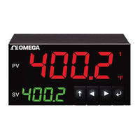
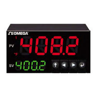
Omega PLATINUM Series, PLATINUM CN32Pt / CN16Pt / CN8Pt Manual
Brand:
Omega
| Category:
Temperature Controller
| Size: 1 MB
Table of Contents
Introduction
Wiring Instructions
Back Panel Connections
Connecting Power
Connecting Inputs
Connecting Outputs
PLATINUM Series Navigation
Description of Button Actions
Menu Structure
Level 1 Menu
Circular Flow of Menus
Complete Menu Structure
Initialization Mode Menu (INIt)
Programming Mode Menu (PRoG)
Operating Mode Menu (oPER)
Safety Considerations
Advertisement
Omega PLATINUM Series User Manual (79 pages)
Brand:
Omega
| Category:
Controller
| Size: 2 MB
Table of Contents
Table of Contents
3
Introduction
8
Description
8
Safety Considerations
9
Wiring Instructions
10
Back Panel Connections
10
(No Isolated Output Expansion Board Installed)
10
(With Isolated Output Expansion Board)
10
Connecting Power
11
Connecting Inputs
12
Connecting Outputs
14
PLATINUM TM Series Navigation
16
Description of Button Actions
16
Menu Structure
16
Level 1 Menu
17
Circular Flow of Menus
17
Complete Menu Structure
18
Initialization Mode Menu (Init)
18
Programming Mode Menu (Prog)
22
Operating Mode Menu (Oper)
25
Reference Section: Initialization Mode (Init)
27
Input Configuration (Init > Inpt)
27
Thermocouple Input Type (Init > Inpt > T.C.)
27
Resistance Temperature Detector (RTD) Input Type (Init > Inpt > Rtd)
28
Thermistor Input Type Configuration (Init > Inpt > Thrm)
28
Process Input Type Configuration (Init > Inpt > Proc)
29
TARE (Init > Tare)
34
LINR (Init > LINR)
34
Display Reading Formats (Init > Rdg)
36
Decimal Point Format (Init > Rdg > Dec.p)
36
Temperature Units (Init > Rdg > °F°C)
36
Display Rounding (Init > Rdg > D.rnd)
37
Filter (Init > Rdg > Fltr)
37
Annunciator Settings (Init > Rdg > ANN.1/ANN.2)
38
Normal Color (Init > Rdg > NCLR)
38
Brightness (Init > Rdg > Brgt)
38
Excitation Voltage (Init > Ectn)
39
Communication (Init > Comm)
39
Protocol (Init > Comm > Usb, Ethn, SER > Prot)
39
Address (Init > Comm > Usb, Ethn, SER > Addr)
40
Serial Communications Parameters (Init > Comm > SER >C.PAR)
41
Safety Features (Init > Sfty)
42
Power on Confirmation (Init > Sfty > Pwon)
42
Operating Mode Confirmation (Init > Sfty > Oper)
42
Setpoint Limits (Init > Sfty > SP.LM)
43
Loop Break Timeout (Init > Sfty > SEN.M > Lpbk)
43
Open Circuit (Init > Sfty > SEN.M > O.crk)
43
Sensor Error Latch (Init > Sfty > SEN.M > E.LAT)
43
Output Break Detection (Init > Sfty > OUT.M > O.brk)
44
Output Error Latch (Init > Sfty > OUT.M > E.LAT)
44
Manual Temperature Calibration (Init > T.cal)
44
No Manual Temperature Calibration Adjustment (Init > T.cal > None)
45
Manual Temperature Calibration Offset Adjustment (Init > T.cal > 1.Pnt)
45
Manual Temperature Calibration Offset and Slope Adjustment (Init > T.cal > 2.Pnt)
45
Temperature Ice Point Calibration (Init > T.cal > ICE.P)
46
Save Current Configuration for All Parameters to a File (Init > SAVE)
46
Load a Configuration for All Parameters from a File (Init > Load)
46
Display Firmware Revision Number (Init > VER.N)
46
Update Firmware Revision (Init > VER.U)
47
Reset to Factory Default Parameters (Init > F.dft)
47
Password-Protect Initialization Mode Access (Init > I.pwd)
47
Password-Protect Programming Mode Access (Init
47
Reference Section: Programming Mode (Prog)
48
Setpoint 1 Configuration (Prog > SP1)
48
Setpoint 2 Configuration (Prog > SP2)
48
Alarm Mode Configuration (Prog > ALM.1, ALM.2)
49
Alarm Type (Prog > ALM.1, ALM.2 > Type)
49
Absolute or Deviation Alarm (Prog > ALM.1, ALM.2 > Type > Ab.DV)
50
Alarm High Reference (Prog > ALM.1, ALM.2 > Type > ALR.H)
50
Alarm Low Reference (Prog > ALM.1, ALM.2 > Type > ALR.L)
51
Alarm Color (Prog > ALM.1, ALM.2 > A.CLR)
51
Alarm High High / Low Low Offset Value (Prog > ALM.1, ALM.2 > HI.HI)
51
Alarm Latching (Prog > ALM.1, ALM.2 > Ltch)
52
Alarm Normally Closed, Normally Open (Prog > ALM.1, ALM.2 > Ctcl)
52
Alarm Power-On Behavior (Prog > ALM.1, ALM.2 > a
52
Alarm on Delay (Prog > ALM.1, ALM.2 > De.on)
52
Alarm off Delay (Prog > ALM.1, ALM.2 > De.of)
53
Output Channel 1-6 Configuration (Prog > Out.1-Out.6)
53
Output Channel Mode (Prog > Out1-Out6 > Mode)
54
Output Cycle Pulse Width (Prog > Out1-Out6 > Cycl)
56
Analog Output Range (Prog > Out1-Out6 > RNGE)
57
PID Configuration (Prog > Pid.s)
58
Action Response (Prog > Pid > Actn)
58
Autotune Timeout (Prog > Pid > A.to)
58
Autotune (Prog > Pid > TUNE)
58
PID Gain Settings (Prog > Pid > GAIN)
59
Relative Cool Gain (Prog > Pid > Rcg)
60
Control Offset (Prog > Pid > Ofst)
60
Deadband (Prog > Pid > Dead)
60
Low Output Clamping Limit (Prog > Pid > %Lo)
60
High Output Clamping Limit (Prog > Pid > %HI)
61
Adaptive Tuning (Prog > Pid > Adpt)
61
PID.2 Configuration (Prog > Pid.2)
61
Remote Setpoint Configuration (Prog > RM.SP)
61
Cascade Control Using Remote Setpoint
63
Multi-Ramp/Soak Mode Parameters (Prog > M.RMP)
64
Multi-Ramp/Soak Mode Control (Prog > M.RMP > R.ctl)
64
Select Program (Prog > M.RMP > S.PRG)
65
Multi-Ramp/Soak Tracking (Prog > M.RMP > M.trk)
65
Time Format (Prog > M.RMP > Tim.f)
65
Program End Action (Prog > M.RMP > E.ACT)
66
Number of Segments (Prog > M.RMP > N.SEG)
66
Segment Number for Editing (Prog > M.RMP > S.SEG)
66
More on Multi-Ramp/Soak Programming
67
Reference Section: Operating Mode (Oper)
69
Normal Run Mode (Oper > RUN)
69
Change Setpoint 1 (Oper > SP1)
69
Change Setpoint 2 (Oper > SP2)
70
Manual Mode (Oper > MANL)
70
Pause Mode (Oper > PAUS)
71
Stop Process (Oper > Stop)
71
Clear Latched Alarms (Oper > L.rst)
71
Display Valley Reading (Oper > Valy)
71
Display Peak Reading (Oper > Peak)
72
Standby Mode (Oper > Stby)
72
Standby Mode (Oper > Tare)
72
Specifications
73
Inputs
73
Control
73
Outputs
74
Communications (USB Standard, Optional Serial and Ethernet)
74
Isolation
74
General
75
Approvals Information
77
Omega PLATINUM Series User Manual (61 pages)
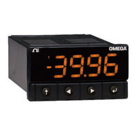
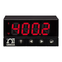
Temperature & Process Controllers
Brand:
Omega
| Category:
Controller
| Size: 3 MB
Table of Contents
Table of Contents
3
Introduction
7
Description
7
Using this Manual
8
Safety Considerations
9
Wiring Instructions
10
1.4.1 Back Panel Connections
10
1.4.2 Connecting Power
11
1.4.3 Connecting Inputs
11
1.4.4 Connecting Outputs
13
PLATINUM TM Series Navigation
14
Description of Button Actions
14
Menu Structure
14
Level 1 Menu
14
Circular Flow of Menus
15
Complete Menu Structure
15
Initialization Mode Menu (Init)
15
Programming Mode Menu (Prog)
19
Operating Mode Menu (Oper)
21
Reference Section: Initialization Mode (Init)
22
Input Configuration (Init > Inpt)
22
Thermocouple Input Type (Init > Inpt > T.C.)
22
Resistance Temperature Detector (RTD) Input Type (Init > Inpt > Rtd)
23
Thermistor Input Type Configuration (Init > Inpt > Thrm)
24
Process Input Type Configuration (Init > Inpt > Proc)
24
Display Reading Formats (Init > Rdg)
25
Decimal Point Format (Init > Rdg > Dec.p)
25
Temperature Units (Init > Rdg > °F°C)
25
Filter (Init > Rdg > Fltr)
26
Annunciator Settings (Init > Rdg > ANN.1/ANN.2)
26
Normal Color (Init > Rdg > NCLR)
27
Brightness (Init > Rdg > Brgt)
27
Excitation Voltage (Init > Ectn)
27
Communication (Init > Comm)
28
Protocol (Init > Comm > Usb, Ethn, SER > Prot)
28
Address (Init > Comm > Usb, Ethn, SER > Addr)
29
Serial Communications Parameters (Init > Comm > SER >C.PAR)
29
Safety Features (Init > Sfty)
31
Power on Confirmation (Init > Sfty > Pwon)
31
Operating Mode Confirmation (Init > Sfty > Oper)
31
Setpoint Limits (Init > Sfty > SP.LM)
31
Loop Break Timeout (Init > Sfty > Lpbk)
32
Open Circuit (Init > Sfty > O.crk)
32
Manual Temperature Calibration (Init > T.cal)
32
No Manual Temperature Calibration Adjustment (Init > T.cal > None)
33
Manual Temperature Calibration Offset Adjustment (Init > T.cal > 1.Pnt)
33
Manual Temperature Calibration Offset and Slope Adjustment (Init > T.cal > 2.Pnt)
33
Temperature Ice Point Calibration (Init > T.cal > ICE.P)
33
Save Current Configuration for All Parameters to a File (Init > SAVE)
33
Load a Configuration for All Parameters from a File (Init > Load)
34
Display Firmware Revision Number (Init > VER.N)
34
Update Firmware Revision (Init > VER.U)
34
Reset to Factory Default Parameters (Init > F.dft)
34
Password-Protect Initialization Mode Access (Init > I.pwd)
34
Password-Protect Programming Mode Access (Init
34
Reference Section: Programming Mode (Prog)
35
Setpoint 1 Configuration (Prog > SP1)
35
Setpoint 2 Configuration (Prog > SP2)
35
Alarm Mode Configuration (Prog > ALM.1, ALM.2)
36
Alarm Type (Prog > ALM.1, ALM.2 > Type)
36
Absolute or Deviation Alarm (Prog > ALM.1, ALM.2 > Type > Ab.DV)
37
Alarm High Reference (Prog > ALM.1, ALM.2 > Type > ALR.H)
37
Alarm Low Reference (Prog > ALM.1, ALM.2 > Type > ALR.L)
37
Alarm Color (Prog > ALM.1, ALM.2 > A.CLR)
38
Alarm High High / Low Low Offset Value (Prog > ALM.1, ALM.2 > HI.HI)
38
Alarm Latching (Prog > ALM.1, ALM.2 > Ltch)
38
Alarm Normally Closed, Normally Open (Prog > ALM.1, ALM.2 > Ctcl)
39
Alarm Power-On Behavior (Prog > ALM.1, ALM.2 > a
39
Alarm on Delay (Prog > ALM.1, ALM.2 > De.on)
39
Alarm off Delay (Prog > ALM.1, ALM.2 > De.of)
39
Output Channel 1-3 Configuration (Prog > Out.1-Out.3)
40
Output Channel Mode (Prog > Out1-Out3 > Mode)
40
Output Channel 1-4 Configuration (Prog > Out.1-Out.4)
40
Output Cycle Pulse Width (Prog > Out1-Out3 > Cycl)
42
Analog Output Range (Prog > Out1-Out3 > RNGE)
43
PID Configuration (Prog > Pid.s)
43
Action Response (Prog > Pid > Actn)
43
PID Configuration (Prog > Pid)
43
Autotune Timeout (Prog > Pid > A.to)
44
Autotune (Prog > Pid > Auto)
44
PID Gain Settings (Prog > Pid > GAIN)
44
Low Output Clamping Limit (Prog > Pid > %Lo)
45
High Output Clamping Limit (Prog > Pid > %HI)
45
Adaptive Tuning (Prog > Pid > Adpt)
45
Remote Setpoint Configuration (Prog > RM.SP)
46
5.6.1 Cascade Control Using Remote Setpoint
47
Multi-Ramp/Soak Mode Parameters (Prog > M.RMP)
48
Multi-Ramp/Soak Mode Control (Prog > M.RMP > R.ctl)
48
Select Program (Prog > M.RMP > S.PRG)
49
Multi-Ramp/Soak Tracking (Prog > M.RMP > M.trk)
49
Time Format (Prog > M.RMP > Tim.f)
49
Program End Action (Prog > M.RMP > E.ACT)
49
Number of Segments (Prog > M.RMP > N.SEG)
50
Segment Number for Editing (Prog > M.RMP > S.SEG)
50
5.7.8 more on Multi-Ramp/Soak Programming
51
Reference Section: Operating Mode (Oper)
52
Normal Run Mode (Oper > RUN)
52
Change Setpoint 1 (Oper > SP1)
53
Change Setpoint 2 (Oper > SP2)
53
Manual Mode (Oper > MANL)
53
Pause Mode (Oper > PAUS)
53
Stop Process (Oper > Stop)
54
Clear Latched Alarms (Oper > L.rst)
54
Display Valley Reading (Oper > Valy)
54
Display Peak Reading (Oper > Peak)
54
Standby Mode (Oper > Stby)
54
Specifications
55
Inputs
55
Control
55
Outputs
56
Communications (USB Standard, Optional Serial and Ethernet)
56
Isolation
56
General
56
Approvals Information
59
Advertisement
Omega PLATINUM Series User Manual (61 pages)
Temperature, Process and Strain Meters
Brand:
Omega
| Category:
Measuring Instruments
| Size: 5 MB
Table of Contents
Table of Contents
3
Introduction
6
1 Description
6
2 Safety C Onsiderations
7
Wiring I Nstructions
8
3 Back P Anel C Onnections
8
Connecting P Ower
9
Connecting I Nputs
10
Connecting O Utputs O N U Nits W Ith a Larm R Elays
12
Connecting O Utput O N U Nit W Ith a Larm R Elay
12
PLATINUM TMS Eries N Avigation
13
4 Description O F B Utton a Ctions
13
Menu S Tructure
13
Level 1 M Enu
14
Circular F Low O F M Enus
14
Complete M Enu S Tructure
15
5 Initialization M Ode M Enu ( Init)
15
Programming M Ode M Enu ( Prog)
19
Operating M Ode M Enu ( Oper)
21
Reference S Ection: I Nitialization M Ode ( Init)
22
6 Input C Onfiguration ( Init > I Npt)
22
Thermocouple I Nput T Ype ( Init > I Npt > T
22
Thermistor I Nput T Ype C Onfiguration ( Init > I Npt > T HRM)
23
Resistance T Emperature D Etector ( RTD) I Nput T Ype ( Init > I Npt > R Td) 2
23
Process I Nput T Ype C Onfiguration ( Init > I Npt > P Roc)
24
TARE ( Init > T ARE)
29
LINR ( Init > L INR)
29
Reference S Ection: I Nitialization M Ode ( Init)
29
Display R Eading F Ormats ( Init > R
31
Decimal P Oint F Ormat ( Init > R Dg > D EC
31
Temperature U Nits ( Init > R Dg > ° F
31
Display R Ounding ( Init > R Dg > D .Rnd)
32
Filter ( Init > R Dg > F Ltr)
32
Annunciator S Ettings ( Init > R Dg > a NN.1/ANN.2)
33
Normal C Olor ( Init > R Dg > N CLR)
33
Brightness ( Init > R Dg > B Rgt)
33
Excitation V Oltage ( Init > E Ctn)
34
Communication ( Init > C Omm)
34
Protocol ( Init > C Omm > U Sb, E Thn, S er > P Rot)
35
Address ( Init > C Omm > U Sb, E Thn, S er > a Ddr)
37
Serial C Ommunications P Arameters ( Init > C Omm > S er > C.PAR)
37
Safety F Eatures ( Init > S Fty)
38
Power O N C Onfirmation ( Init > S Fty > P Won)
38
Operating M Ode C Onfirmation ( Init > S Fty > O PER)
39
Setpoint L Imits ( Init > S Fty > S P
39
Manual T Emperature C Alibration ( Init > T .CAL)
40
Temperature I Ce P Oint C Alibration ( Init > T .CAL > I CE
41
Save C Urrent C Onfiguration F or a Ll P Arameters T O a F Ile ( Init > S AVE)
41
Load a C Onfiguration F or a Ll P Arameters F Rom a F Ile ( Init > L Oad)
41
Display F Irmware R Evision N Umber ( Init > V er
41
Update F Irmware R Evision ( Init > V er
42
Reset T O F Actory D Efault P Arameters ( Init > F .Dft)
42
Password--Protect I Nitialization M Ode a Ccess ( Init > I .Pwd)
42
Password--Protect P Rogramming M Ode a Ccess ( Init > P .Pwd)
42
Reference S Ection: P Rogramming M Ode ( Prog)
43
7 Setpoint 1 C Onfiguration ( Prog > S P1)
43
Setpoint 2 C Onfiguration ( Prog > S P2)
43
Alarm M Ode C Onfiguration ( Prog > a LM.1, a
43
Alarm T Ype ( Prog > a LM.1, a LM.2 > T Ype)
44
Alarm H Igh R Eference ( Prog > a LM.1, a LM.2 > T Ype > a LR
45
Alarm L Ow R Eference ( Prog > a LM.1, a LM.2 > T Ype > a LR
45
Absolute O R D Eviation a Larm ( Prog > a LM.1, a LM.2 > T Ype > a B.DV) 4
45
Alarm C Olor ( Prog > a LM.1, a LM.2 > a .CLR)
46
Alarm L Atching ( Prog > a LM.1, a LM.2 > L Tch)
47
Alarm P Ower--On B Ehavior ( Prog > a LM.1, a LM.2 > a .P
47
Alarm O N D Elay ( Prog > a LM.1, a LM.2 > D E
47
Alarm O Ff D Elay ( Prog > a LM.1, a LM.2 > D E.of)
48
Output C Hannel 1 -6 C Onfiguration ( Prog > O Ut.1-Out.6)
48
Output C Hannel M Ode ( Prog > D Tr1, D Tr2 > M Ode)
49
Output C Ycle P Ulse W Idth ( Prog > O Ut1-Out6 > C Ycl)
51
Analog O Utput R Ange ( Prog > O Ut1-Out6 > R NGE)
51
Reference S Ection: O Perating M Ode ( Oper)
52
8 Normal R un M Ode ( Oper > R
52
Change S Etpoint 1 ( Oper > S P1)
52
Change S Etpoint 2 ( Oper > S P2)
53
Clear L Atched a Larms ( Oper > L .Rst)
53
Display V Alley R Eading ( Oper > V Aly)
53
Reference S Ection: O Perating M Ode ( Oper)
53
Change S Etpoint 1 ( Oper > S P1)
53
Display P Eak R Eading ( Oper > P Eak)
54
Standby M Ode ( Oper > S Tby)
54
Standby M Ode ( Oper > T ARE)
54
Specifications
55
9 Inputs
55
Outputs ( Optional W Ith " --AL" C Onfigurations)
55
Communications ( USB S Tandard, O Ptional S Erial a Nd E Thernet)
55
Isolation
56
General
56
10 Approvals I Nformation
58
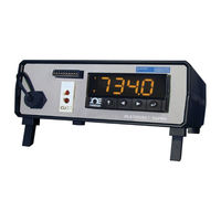
Omega PLATINUM Series User Manual (24 pages)
Universal Temperature & Process Benchtop Meter with Alarms
Brand:
Omega
| Category:
Measuring Instruments
| Size: 2 MB
Table of Contents
Table of Contents
3
Section 1 Introduction
5
Safety and Precautions
5
Cautions and IEC Symbols
5
Table 1. IEC Symbols
5
Statement on Marking
6
Available Models
6
Communication
6
Reference Manuals
6
Table 2. Model Features
6
Table 3. Supporting Documents
6
Section 2 Unpacking
7
Inspection
7
Figure 1. Accessories Packaged with MDS8PT Unit
7
Table 4. Package Contents
7
Power Cords
8
Table 5. Optional Power Cords
8
Section 3 Hardware Setup
9
MDS8PT Front Panel
9
Figure 2. MDS8PT Front Panel
9
Table 6. Front Panel Components List
9
10-Pin Connector
10
Figure 3. 10-Pin Connector Input Pin Assignments
10
Table 7. Sensor Inputs Assignments
10
RTD Wiring Diagram Connector
11
Process Current Wiring Diagram
11
Figure 4. RTD Wiring Diagram
11
Figure 5. 4-20 Ma Sensor Wiring Diagram
11
Universal Thermocouple Connector
12
Figure 6. Mini/Standard Thermocouple
12
MDS8PT Rear Panel
13
Figure 7. MDS8PT Rear Panel
13
Table 8. Rear Panel Component Locations
13
Screw Terminals
14
Figure 8. Benchtop Meter Wiring Diagram
14
Table 9. Configuration For Terminals
14
Section 4 Configuration and Programming
15
Controls
15
Figure 9. Mds8Pt Led Display
15
Menu Structure
16
Figure 10. Circular Flow of Menus
16
Selecting an Input
17
Table 10. Selecting an Input
17
Alarm Configuration (Prog > Alm. #)
18
Setting Alarm Type
18
Figure 11. Alarm Range Option Diagram
18
Setting Alarm High/Low References
19
Setting The Alarm Color (Prog > Alm.# > A.clr)
19
Activating A Relay (Prog > Dtr# > Mode)
19
Analog Output
20
Select an Output Type
20
Set Mode to Retransmission
20
Set Scaling
20
Figure 12. Alarm Scaling Diagram
20
Section 5 Specification
21
Approval Information
21
Table 11. Benchtop Meter Specifications Summary
21
Section 6 Maintenance
22
Table 12. Fuses
22
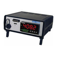
Omega PLATINUM Series User Manual (16 pages)
Universal Benchtop Digital Controller
Brand:
Omega
| Category:
Controller
| Size: 2 MB
Table of Contents
Table of Contents
2
1 Introduction
3
Safety and Precautions
3
Cautions and IEC Symbols
3
Statement on CE Marking
3
Available Models
3
Communication Options
4
Reference Manuals
4
2 Unpacking
4
Inspection
4
Power Cords
5
3 Hardware Setup
5
Front Panel
5
10-PIN Connector Wiring Diagrams
6
Universal Thermocouple Connector
7
Rear Panel
8
Isolated Analog Output
8
4 Configuration and Programming
9
PLATINUM Series Navigation
9
Selecting an Input (Init>Inpt)
10
Set the Setpoint 1 Value (Prog > SP1)
10
Set up the Control Output
11
Select an Output Channel (Prog > Str1/Dc1/Ian1)
11
On/Off Control Mode (Prog > {Output} > Mode > On.of)
11
PID Control
12
PID Configuration (Prog > Pid.s)
12
Follow These Steps to Run an Autotune Procedure
12
Retransmission Using the Analog Output
13
Select an Output Type
13
Set Mode to Retransmission
13
Set Scaling
13
5 Specifications
14
6 Maintenance
15
Cleaning
15
Calibration
15
Fuse Specifications and Replacement
15
Advertisement
Related Products
Omega PCL340 Series
Omega PHH-224
Omega PX880 and PX881
Omega PHB21
Omega PHH444
Omega PHCN-962
Omega PHH-SD1
Omega PX2088
omega PL402XA
Omega PL403A
Omega Categories
Measuring Instruments
Thermometer
Oven
Cooktop
Watch
More Omega Manuals
Login
Sign In
OR
Sign in with Facebook
Sign in with Google
Upload manual
Upload from disk
Upload from URL