Omega PLATINUM Series User Manual
Universal temperature & process benchtop meter with alarms
Hide thumbs
Also See for PLATINUM Series:
- Quick start manual ,
- User manual (61 pages) ,
- User manual (79 pages)
Table of Contents
Advertisement
Quick Links
Advertisement
Table of Contents

Related Manuals for Omega PLATINUM Series


Summary of Contents for Omega PLATINUM Series
- Page 1 MDS8PT Universal Temperature & Process Benchtop Meter with Alarms...
- Page 2 For Other Locations Visit omega.com/worldwide PROPRIETARY STATEMENT - This manual contains proprietary design information representing Omega Engineering Inc. It is intended solely for the Information and use of parties operating and maintaining the equipment described herein. Such proprietary information may not be used, reproduced, or...
-
Page 3: Table Of Contents
TABLE OF CONTENTS SECTION 1 INTRODUCTION 1.1 Safety and Precautions ..................1 1.2 Cautions and IEC Symbols .................. 1 1.3 Statement on Marking ................2 1.4 Available Models ....................2 1.5. Communication ....................2 1.6 Reference Manuals ....................2 SECTION 2 UNPACKING 2.1 Inspection ...................... - Page 4 TABLE OF FIGURES Figure 1. Accessories Packaged with MDS8PT Unit ........... 3 Figure 2. MDS8PT Front Panel .................. 5 Figure 3. 10-Pin Connector Input Pin Assignments ............. 6 Figure 4. RTD Wiring Diagram .................. 7 Figure 5. 4-20 mA Sensor Wiring Diagram ..............7 Figure 6.
-
Page 5: Section 1 Introduction
SECTION 1 INTRODUCTION The MDS8PT Platinum Series Universal Benchtop Digital Meter (Benchtop Meter), is ideal for laboratory and other application uses requiring portable temperature or process measurement. It features a universal input configured for use with a thermocouple, RTD, Thermistor or Voltage/Current signal. The Benchtop Meter is factory configured and calibrated for use out of the box. It is important to read and follow all precautions and instructions in this manual and other referenced manuals, before operating or commissioning this device, as it contains important information relating to safety and EMC. -
Page 6: Statement On Marking
-330 Dual Alarm Relays (ONLY) 1.5. Communication The Platinum Series Benchtop Meter uses a standard USB port compatible with the Omega Platinum configuration software, available from the Omega website; as well as Optional serial and Ethernet connectivity manuals. All communication options support both the Omega ASCII protocol, Modbus ASCII, Modbus RTU and Modbus TCP/IP. -
Page 7: Section 2 Unpacking
SECTION 2 UNPACKING Read the packing list, it is important to verify all equipment shipped has been delivered as shown in Figure 1 and Table 4. If there are any questions about the shipment please email or call the Customer Service Department listed in this manual. Inspection Inspect the shipment container and equipment for any signs of damage. -
Page 8: Power Cords
Power Cords Electrical power is delivered to the Benchtop Meter by an AC power cord to plug into the IEC 60320 C-13 power socket located on the rear panel of the unit. Refer to Section 3.2 Figure 7 for detailed connections. The input power is fused. -
Page 9: Section 3 Hardware Setup
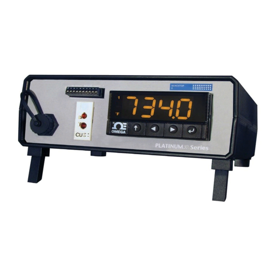
SECTION 3 HARDWARE SETUP The hardware connections and configuration to operate the Universal Benchtop Digital Meter. MDS8PT Front Panel The controls, indicators and input connections of the Benchtop Meter are shown in Figure 2. BENCHTOP INPUTS CP + CP - PLATINUM Series Figure 2. MDS8PT Front Panel. (Not to scale) Table 6. Front Panel Compnents List. Item Name Description... -
Page 10: 10-Pin Connector
3.1.1 10-Pin Connector Figure 3 shows the10-pin connector with corresponding input pin assignments. Sensor selection is firmware-controlled, and no jumper settings are required to switch between different sensor types. Figure 3. 10-Pin Connector Input Pin Assignments. Pin No. Code Description ARTN Analog return signal (analog ground) for sensors. AIN+ Analog positive input AIN- Analog negative input APWR... -
Page 11: Rtd Wiring Diagram Connector
3.1.2 RTD Wiring Diagram Connector Figure 4 illustrates the wiring diagram for connecting a platinum RTD. A two-wire RTD requires an external jumper from Pin 1 to Pin 4. Figure 4. RTD Wiring Diagram. 3.1.3 Process Current Wiring Diagram Figure 5 illustrates the wiring diagram for connecting 4-20mA Sensor using internal or external excitation. -
Page 12: Universal Thermocouple Connector
3.1.4 Universal Thermocouple Connector The Benchtop Meter accepts both Mini and Standard thermocouple connectors using the Universal Panel Jack shown in Figure 6. The Benchtop Meter has internal cold junction compensation and is compatible with thermocouples listed in Table 7 on page 6. Figure 6. -
Page 13: Mds8Pt Rear Panel
MDS8PT Rear Panel The Rear Panel connections for the Benchtop Meter are shown in Figure 7 below. ETHERNET O / I ALARM 1 ISO ANALOG ALARM 2 AC MAIN OUTPUT 90-240 VAC ~ 50 / 60 Hz Figure 7. MDS8PT Rear Panel. (Not to scale) Table 8. -
Page 14: Screw Terminals
3.2.1 Screw Terminals Figure 8 shows the wiring confdigurations of the rear terminals connections for Alarms and optional Isolated Analog terminals. 0-24mA OUTPUT SOURCE 0-10V OUTPUT SOURCE ISO ANALOG ALARMS 1 & 2 Figure 8. Benchtop Meter Wiring Diagram. Table 9. Configuration for Terminals. Terminal Numbers Configuration Alarms 1 and 2*... -
Page 15: Section 4 Configuration And Programming
SECTION 4 CONFIGURATION AND PROGRAMMING Controls The UP Button moves up a level in the menu structure. Pressing and holding the UP Button navigates to the top level of any menu (oPER, PRoG, or INIt). This is a useful way of reorienting if you get lost in the menu structure. -
Page 16: Menu Structure
Menu Structure The menu structure of the Platinum Series Display Meter is divided into three main Level-1 Modes: Initialization (INIt), Programming (PRoG) and Operations (oPER). Initialization Mode: These settings are rarely changed after initial set up. They include transducer types, calibration, etc. These settings can be password protected. -
Page 17: Selecting An Input
Selecting an Input The Benchtop Meter features a User Programmable Universal Input. Select the input type using TABLE 10. Initialization Mode Menu, below. Refer to Section 3.1.2 to 3.1.3 for Input Wiring Diagrams. Level Level Level Level Level Level Level Notes INIT INPt... -
Page 18: Alarm Configuration (Prog > Alm. #)
Alarm Low parameter, used for Alarm trigger calculations. A.CLR Alarm Color indication. For a more detailed discussion of setting up and configuring the Alarm functions, refer to the Platinum Series Temperature and Process Meters - User’s Manual (M5460). 4.4.1 Setting Alarm Type Use the Alarm Type (tyPE) parameter to control the basic behavior of the selected alarm. -
Page 19: Setting Alarm High/Low References
4.4.2 Setting Alarm High/Low References: • Alarm High Reference (PRoG > ALM.#> ALR.H). • Alarm Low Reference (PRoG > ALM.# > ALR.L). 1. Use the button to select a digit to change; 2. Then select the button to increment the digit; 3. Save the setting with the button. 4.4.3 Setting the Alarm Color (PRoG > ALM.# > A.CLR) The Benchtop Meter can change color in the display when an alarm is triggered. -
Page 20: Analog Output
Analog Output The optional Analog Output can be configured to transmit a Voltage or current signal proportional to the Input. Select the output type in the PRog. > IAN.1 > RNGE menu. For a more detailed discussion of setting up and configuring the Analog Output. Refer to the Platinum Series Temperature and Process Controllers - User’s Manual (M5451). 4.5.1 Select an Output Type The scaling of input readings to output voltage or current is fully user configurable. Type... -
Page 21: Section 5 Specification
Case - Plastic (ABS), Handle -Anodized Aluminum Material: 20.95 W x 9.525 H x 20.32 cm D Size: (8.25 W x 3.75 H x 8” D) Weight: MDS Platinum Series 1.36 kg (3 lb) Approval Information EMC: 2014/30/EU (EMC Directive) -
Page 22: Section 6 Maintenance
SECTION 6 MAINTENANCE These are the maintenance procedures required to keep the Benchtop Meter in optimal performance. Calibration This unit is calibrated to give optimum performance over its full operating range. Additional user calibration is available with adjustable gain and offset as well as ice paint calibration. - Page 23 2016...
- Page 24 Where Do I Find Everything I Need for Process Measurement and Control? OMEGA…Of Course! Shop online at omega.com TEMPERATURE Thermocouple, RTD & Thermistor Probes, Connectors, Panels & Assemblies Wire: Thermocouple, RTD & Thermistor Calibrators & Ice Point Refer e nces Recorders, Controllers &...
Need help?
Do you have a question about the PLATINUM Series and is the answer not in the manual?
Questions and answers