Table of Contents
Advertisement
Quick Links
Advertisement
Table of Contents

Related Manuals for Omega CN8EPt


Summary of Contents for Omega CN8EPt
- Page 1 CN32Pt, CN16Pt, CN16PtD, CN8Pt, CN8PtD, CN8EPt Temperature & Process Controllers...
- Page 2 Fax: (203) 359-7700 e-mail: info@omega.com For Other Locations Visit omega.com/worldwide The information contained in this document is believed to be correct, but OMEGA accepts no liability for any errors it contains, and reserves the right to alter specifications without notice.
-
Page 3: Table Of Contents
Open Circuit (INIt > SFty > SEN.M > o.CRk) ................. 43 6.7.6 Sensor Error Latch (INIt > SFty > SEN.M > E.LAT) ..............43 6.7.7 Output Break detection (INIt > SFty > OUT.M > o.bRK) ............44 M5451 Omega Engineering | www.omega.com... - Page 4 Remote Setpoint Configuration (PRoG > RM.SP) ................ 61 7.7.1 Cascade Control using Remote Setpoint ................63 Multi-Ramp/Soak Mode Parameters (PRoG > M.RMP) .............. 64 7.8.1 Multi-Ramp/Soak Mode Control (PRoG > M.RMP > R.CtL) ..........64 M5451 Omega Engineering | www.omega.com...
- Page 5 Figure 6 – Process Current Wiring Hookup with Internal and External Excitation ....... 13 Figure 7 – Process Voltage Wiring Hookup with optional Ratiometric Voltage connection....13 Figure 8 – PLATINUM Series Displays (CN8DPt and CN8EPt Shown) ............16 Figure 9 – Circular Flow of Menus......................17 Figure 10 –...
- Page 6 Figure 12 – Generic Cascade Control Diagram ..................63 Figure 13 – Heat Exchanger with Cascade Control .................. 63 Figure 14 – Ramp & Soak Process Variable Period of Time................ 67 Figure 15 – Ramp & Soak Current Process Variable................... 68 M5451 Omega Engineering | www.omega.com...
- Page 7 The Reference Section—encompassing Initialization Mode in Section 6, Programming Mode in Section and Operating Mode in Section 8—will provide more detail on what parameter and command preferences; such as how they operate, and why to choose a specific value. M5451 Omega Engineering | www.omega.com...
-
Page 8: Introduction
Some additional standard features are remote Setpoint for cascaded control setups, High-high/Low-low Alarm functionality, external latch reset, external Ramp and Soak program initiation, combination Heat/Cool Control Mode, configuration save and transfer, and configuration password protection. M5451 Omega Engineering | www.omega.com... -
Page 9: Safety Considerations
Failure to follow all instructions and warnings is at your own risk and may result in property damage, bodily injury and/or death. Omega Engineering is not responsible for any damages or loss arising or resulting from any failure to follow any and all instructions or observe any and all warnings. -
Page 10: Wiring Instructions
8-Pin Power / Base Outputs Connector 10-Pin Input Connector Figure 1 – CN8Pt, CN8DPt and CN8EPt Models: Back Panel Connections (No Isolated Output Expansion Board Installed) Optional Isolated Output Expansion Ethernet Connector if EIP Option Installed... -
Page 11: Connecting Power
Overvoltage Category and pollution degree as the standard AC unit (90–300 Vac). The Safety European Standard EN61010-1 for measurement, control, and laboratory equipment requires that fuses must be specified based on IEC127. This standard specifies the letter code “T” for a Time-lag fuse. M5451 Omega Engineering | www.omega.com... -
Page 12: Connecting Inputs
*For Remote Setpoint with an RTD, Pin 1 on the Output Connector must be used for the RtN instead of Pin 1 on the Input Connector. Remote Setpoint is not available if using an RTD sensor and have an SPDT (Type 3) Output installed. ** Requires external connection to pin 4 M5451 Omega Engineering | www.omega.com... - Page 13 Figure 6 – Process Current Wiring Hookup with Internal and External Excitation +/- 10, +/- 1 and +/- 0.1 +/- 0.1and +/- .05 Differential / Single End Voltage Ratiometric Voltage Reference Voltage Figure 7 – Process Voltage Wiring Hookup with optional Ratiometric Voltage connection. M5451 Omega Engineering | www.omega.com...
-
Page 14: Connecting Outputs
SPST, DC pulse, DC pulse SPST, DC pulse, analog V/C+ SSR, SSR SSR, SSR, DC pulse SSR, SSR, analog V/C+ DC pulse, DC pulse DC pulse, DC pulse, DC pulse DC pulse, DC pulse, analog V/C+ M5451 Omega Engineering | www.omega.com... - Page 15 AC power neutral in pin Relay Common/SSR AC power AC power hot in pin N.C. Normally closed relay load Negative DC power in pin DC Ground Positive DC power in pin Load for DC pulse V/C+ Load for analog M5451 Omega Engineering | www.omega.com...
-
Page 16: Platinum Tm Series Navigation
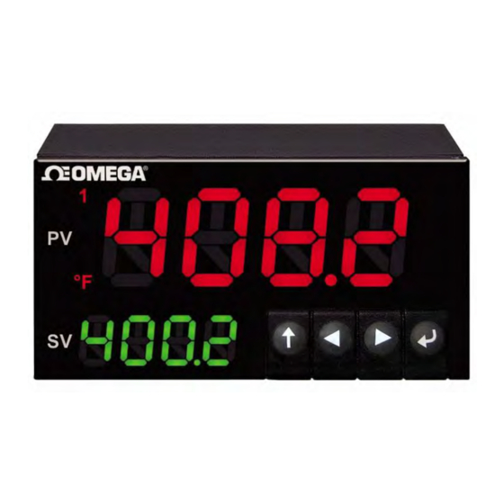
Temperature Units Alarm Annunciators Program Buttons Figure 8 – PLATINUM Series Displays (CN8DPt and CN8EPt Shown) 4.1 Description of Button Actions The UP button moves up a level in the menu structure. Pressing and holding the UP button navigates to the top level of any menu (oPER, PRoG, or INIt). This can useful if you get lost in the menu structure. -
Page 17: Level 1 Menu
Operating Mode: This mode allows users to switch between Run Mode, Standby Mode, oPER Manual Mode, etc. 4.4 Circular Flow of Menus The following diagram shows how to use the LEFT and RIGHT buttons to navigate around a menu. Figure 9 – Circular Flow of Menus. M5451 Omega Engineering | www.omega.com... -
Page 18: Complete Menu Structure
Process input range: 0 to 24 mA – +-10 Process input range: -10 to +10 V Note: +- 1.0 and +-0.1 support SNGL, dIFF and RtIO tYPE tYPE SNGL Process input range: -1 to +1 V M5451 Omega Engineering | www.omega.com... - Page 19 Note: Four digit displays offer 2 annunciators, Six digit displays offer 6 ANN.n ALM.1 Alarm 1 status mapped to “1” ALM.2 Alarm 2 status mapped to “1” oUt# Output state selections by name NCLR Default display color: Green M5451 Omega Engineering | www.omega.com...
- Page 20 USB requires Address EtHN PRot Ethernet port configuration AddR ____ Ethernet “Telnet” requires Address PRot Serial port configuration C.PAR bUS.F 232C Single device Serial Comm Mode Multiple devices Serial Comm Mode bAUd 19.2 Baud rate: 19,200 Bd M5451 Omega Engineering | www.omega.com...
- Page 21 Output break detection disabled ENbl P.dEV ____ Output break process deviation P.tME ____ Output break time deviation oUt2 oUt2 is replaced by output type oUt3 oUt3 is replaced by output type E.LAt ENbl Latch output error enabled M5451 Omega Engineering | www.omega.com...
-
Page 22: Programming Mode Menu (Prog)
Deviation Mode; triggers are deviations from SP2 CN.SP Tracks the Ramp & Soak instantaneous setpoint ALR.H ____ Alarm high parameter for trigger calculations ALR.L ____ Alarm low parameter for trigger calculations A.CLR Red display when Alarm is active M5451 Omega Engineering | www.omega.com... - Page 23 Output is an Alarm using ALM.1 configuration ALM.1 Output is an Alarm using ALM.2 configuration ALM.2 RtRN ____ Process value for oUt1 oUt1 ____ Output value for Rd1 ____ Process value for oUt2 oUt2 ____ Output value for Rd2 M5451 Omega Engineering | www.omega.com...
- Page 24 RS.Lo ____ Min Setpoint for scaled range IN.Lo ____ Input value for RS.Lo RS.HI ____ Max Setpoint for scaled range IN.HI ____ Input value for RS.HI 0–24 0–24 mA 0–10 0–10 V 0–1 0–1 V M5451 Omega Engineering | www.omega.com...
-
Page 25: Operating Mode Menu (Oper)
Clears any latched Alarms; Alarms menu also allows digital input reset VALy Displays the lowest input reading since the VALy was last cleared PEAk Displays the highest input reading since the PEAk was last cleared M5451 Omega Engineering | www.omega.com... - Page 26 PLATINUM Series Controllers User’s Guide Complete Menu Structure Level Level Level Notes Stby Standby Mode, outputs, and Alarm conditions disabled, displays Stby tARE TARE option - only available if enabled in INPt M5451 Omega Engineering | www.omega.com...
-
Page 27: Reference Section: Initialization Mode (Init)
– Type J – Type T – Type E – Type N – Type R – Type S – Type B – Type C Select the indicated type. M5451 Omega Engineering | www.omega.com... -
Page 28: Resistance Temperature Detector (Rtd) Input Type (Init > Inpt > Rtd)
Navigate to the correct setting. Settings include the following: 2.25k – 2,250 Ω thermistor (factory default) – 5,000 Ω thermistor 10k – 10,000 Ω thermistor Select the indicated option. M5451 Omega Engineering | www.omega.com... -
Page 29: Process Input Type Configuration (Init > Inpt > Proc)
Offset = Rd.1 – (Gain * IN.1) Therefore scaling can be done over a subset of the applicable range as this scaling calculation linearly extrapolates in both directions. Select the scaling method to be used. M5451 Omega Engineering | www.omega.com... - Page 30 2.048 reference voltage (Vref) is used and determines the maximum voltage difference. The analog voltages must be within +/- 2.0 volts of the analog ground (ARTN) voltage level, referred to as the Common Mode Voltage. AIN + Reference AIN - Voltage Common Mode Voltage M5451 Omega Engineering | www.omega.com ARTN...
- Page 31 1.5 – 2.5 Vdc and applied between APWR and ARTN. An internal 2.0 k ohm resistor is applied between the APWR and ARTN terminals. AIN + Measured Signal as % of Reference Voltage Reference AIN - Voltage Common Mode Voltage ARTN M5451 Omega Engineering | www.omega.com...
- Page 32 ½ of the voltage generated by the on-board Excitation Voltage. Bridge Element Resistors (R1, R2): ~ 4.7 k ohms. NOTE: An internal 2.0 k ohms resistor is connected between terminal 1 (ARTN) and terminal 4 (APWR). M5451 Omega Engineering | www.omega.com...
- Page 33 Excitation voltage and exact resistor values do not enter into the weight calculation. If (X2 - X1) == 0, the GAIN is set to 1 and the OFFSET is set to 0. M5451 Omega Engineering | www.omega.com...
-
Page 34: Tare (Init > Tare)
Rd.n – Reading low value corresponding to IN.1 signal IN.n – Input signal corresponding to RD.1 In Manual Mode, IN.n is entered manually. In Live Mode, the IN.n option displays the current input signal. Select the scaling parameter to change. M5451 Omega Engineering | www.omega.com... - Page 35 10-point linearization. The use of Live Scaling and Live Linearization is mutually exclusive. If Live scaling is selected the Live Linearization option is disabled and if Live Linearization is selected the Live Scaling option is disabled. M5451 Omega Engineering | www.omega.com...
-
Page 36: Display Reading Formats (Init > Rdg)
NoNE – Default for INPt = PRoC, both temp unit annunciators turned off; if the process level input signal corresponds to a temperature (temperature transmitters for example), the appropriate temperature type annunciator can be chosen. Select the indicated option. M5451 Omega Engineering | www.omega.com... -
Page 37: Display Rounding (Init > Rdg > D.rnd)
16 – 0.8 s 32 – 1.6 s 64 – 3.2 s 128 – 6.4 s – 0.05 s – 0.1 s – 0.2 s Select the indicated option. M5451 Omega Engineering | www.omega.com... -
Page 38: Annunciator Settings (Init > Rdg > Ann.1/Ann.2)
Select the Brightness (bRGt) parameter. Navigate to the desired setting. Settings include the following: HIGH – High display brightness (factory default) MEd – Medium display brightness Low – Low display brightness Select the indicated option. M5451 Omega Engineering | www.omega.com... -
Page 39: Excitation Voltage (Init > Ectn)
Select the Protocol (PRot) parameter. Navigate to the desired setting. Settings include the following: oMEG – (factory default) Omega’s Protocol, using standard ASCII encoding. Further detail on this format is covered in the Communications Manual. M.bUS – Modbus protocol, available as Modbus RTU (RtU, default) or Modbus/ASCII (ASCI). -
Page 40: Address (Init > Comm > Usb, Ethn, Ser > Addr)
Select the Address (AddR) parameter. Set the Address value. The Modbus protocol requires an address field to correctly identify the selected device. The Omega protocol supports an optional address field which is required for Serial channels configured for RS485. Accept the entered value. -
Page 41: Serial Communications Parameters (Init > Comm > Ser >C.par)
Navigate to the desired setting. Settings include the following: – Odd parity used to verify communications (factory default) EVEN – Even parity used to verify communications NoNE – Parity is not used to verify communications Select the indicated option. M5451 Omega Engineering | www.omega.com... -
Page 42: Safety Features (Init > Sfty)
– Pressing the ENTER button in Stby, PAUS, or StoP Modes will start running the current program immediately (factory default) ENbL – Pressing the ENTER button in any Operating Menu Mode will display RUN; pressing the ENTER button again will start running the current program M5451 Omega Engineering | www.omega.com... -
Page 43: Setpoint Limits (Init > Sfty > Sp.lm)
(open circuit, out of range, loop break), the unit will be put in fault mode. Manual intervention is required to clear the error. When E.LAT is disabled, if the fault conditions no longer exist, the unit will resume its previous running state. M5451 Omega Engineering | www.omega.com... -
Page 44: Output Break Detection (Init > Sfty > Out.m > O.brk)
NoNE – No manual calibration (factory default) 1.PNt – Manually create a 1-point calibration 2.PNt – Manually create a 2-point calibration ICE.P – Manually create a 1-point calibration at 0 Select the indicated option. M5451 Omega Engineering | www.omega.com... -
Page 45: No Manual Temperature Calibration Adjustment (Init > T.cal > None)
R.HI – Set high point in degrees, default = 999.9, and associate with input reading Select the indicated setting. Set the Temperature for R.Lo or R.HI. Confirm the value and pair it with the current input reading. M5451 Omega Engineering | www.omega.com... -
Page 46: Temperature Ice Point Calibration (Init > T.cal > Ice.p)
Select the Display Firmware Revision Number (VER.N) function. The currently installed version number is displayed in the format 1.23.4 where “1” is the major revision number, “23” is the minor revision number, and “4” is the bug fix update number. M5451 Omega Engineering | www.omega.com... -
Page 47: Update Firmware Revision (Init > Ver.u)
– Require a password for PRoG Mode; users will be prompted for this password when selecting PRoG Select the indicated setting. If yES, set the numeric password from the range 0000–9999. Confirm the password. M5451 Omega Engineering | www.omega.com... -
Page 48: Reference Section: Programming Mode (Prog)
– The value specified for SP2 indicates an offset (positive or negative) from SP1; this allows SP2 to track any changes to SP1 automatically Select the indicated setting. Set the correct value. Confirm the value. M5451 Omega Engineering | www.omega.com... -
Page 49: Alarm Mode Configuration (Prog > Alm.1, Alm.2)
(Absolute Mode) or within the band around the specified Setpoint as determined by ALR.L and ALR.H (Deviation Mode) Note: Table 5.1 compares the Alarm range options, and Figure 5.1 represents the Alarm range options graphically. Select the indicated setting. M5451 Omega Engineering | www.omega.com... -
Page 50: Absolute Or Deviation Alarm (Prog > Alm.1, Alm.2 > Type > Ab.dv)
Ramp & Soak as specified by the tyPE parameter. Select the desired setting. 7.3.3 Alarm High Reference (PRoG > ALM.1, ALM.2 > tyPE > ALR.H) Select the Alarm High Reference (ALR.H) parameter. Set the Alarm High Reference value. Confirm the value. M5451 Omega Engineering | www.omega.com... -
Page 51: Alarm Low Reference (Prog > Alm.1, Alm.2 > Type > Alr.l)
Process Value is greater than the HI.HI offset value away from the Alarm condition settings (in either direction) Select the indicated option. For oN, set the offset value. Confirm the value. Lo.Lo HI.HI ALR.L ALR.H bELo, HI.Lo. bANd AboV, HI.Lo. Lower Higher Figure 11 – Alarm HI.HI parameter. M5451 Omega Engineering | www.omega.com... -
Page 52: Alarm Latching (Prog > Alm.1, Alm.2 > Ltch)
Set the number of seconds to delay triggering the Alarm. (The default is 0.) This setting can be used to prevent false Alarm triggering when the Process Value only briefly enters an Alarm condition. Confirm the value. M5451 Omega Engineering | www.omega.com... -
Page 53: Alarm Off Delay (Prog > Alm.1, Alm.2 > De.of)
Ramp/Soak event output; the output can also be turned off CyCL – PWM pulse width setting for DC pulse, mechanical relay, and solid state relay outputs RNGE – Sets the voltage or current range for analog outputs Select the indicated setting. M5451 Omega Engineering | www.omega.com... -
Page 54: Output Channel Mode (Prog > Out1-Out6 > Mode)
For Heat / Cool control set the output connected to the heater with ACtN equal to RVRS and the output connected to the cooling device with ACtN set to dRCt. M5451 Omega Engineering | www.omega.com... - Page 55 7.4.3 Analog Output Range (PRoG > oUt1–oUt6 > RNGE) parameter. The retransmission signal is then scaled using the following 4 parameters. The unit will display the first scaling parameter, Rd1, after RtRN is selected. M5451 Omega Engineering | www.omega.com...
-
Page 56: Output Cycle Pulse Width (Prog > Out1-Out6 > Cycl)
7.4.2 Output Cycle Pulse Width (PRoG > oUt1–oUt6 > CyCL) Select the Output Cycle Pulse Width (CyCL) parameter. This parameter is used to set the control signal pulse width in seconds for DC pulse, mechanical relay, and solid state relay (SSR) outputs. M5451 Omega Engineering | www.omega.com... -
Page 57: Analog Output Range (Prog > Out1-Out6 > Rnge)
0–10 – 0 to 10 Volts (factory default) 0–5 – 0 to 5 Volts 0–20 – 0 to 20 mA 4–20 – 4 to 20 mA 0–24 – 0 to 24 mA Select the desired range setting. M5451 Omega Engineering | www.omega.com... -
Page 58: Pid Configuration (Prog > Pid.s)
The Autotune function will select the tuning algorithm depending on the stability of current process and the error difference between current process and the Control Setpoint (SP1). If the process is relatively stable (i.e: at room temperature), a bump test will be performed to determine the plant characteristics. M5451 Omega Engineering | www.omega.com... -
Page 59: Pid Gain Settings (Prog > Pid > Gain)
PID algorithm accordingly. A higher value for this factor can speed up or slow down the response of the system even faster than an increase in the Integral Factor will. Select the indicated setting. Set the desired value. Confirm the value. M5451 Omega Engineering | www.omega.com... -
Page 60: Relative Cool Gain (Prog > Pid > Rcg)
Select the Low Output Clamping Limit (%Lo) parameter. This parameter sets the lower limit of %Power applied to an analog output, or %On time for PWM (pulse width modulated) control used with the other output types. (The default setting is -100.0%.) Set the desired value. Confirm the value. M5451 Omega Engineering | www.omega.com... -
Page 61: High Output Clamping Limit (Prog > Pid > %Hi)
– Do not use a remote Setpoint (factory default) oN – Remote Setpoint replaces Setpoint 1 Note: oFF has no sub-parameters, but oN requires scaling of the remote Setpoint input. Select the indicated setting. M5451 Omega Engineering | www.omega.com... - Page 62 RS.HI – Maximum Setpoint value. Setpoint 1 is set to this value when the analog input signal is IN.HI. IN.HI – Input value in mA or V for RS.HI Select the indicated setting. Set the desired value. Confirm the value. M5451 Omega Engineering | www.omega.com...
-
Page 63: Cascade Control Using Remote Setpoint
(FT). The output of the secondary (flow) controller is a control signal for the proportional valve controlling the flow of the steam. By isolating the slowly changing effluent temperature control loop from the rapidly changing flow control loop, a more predictable, robust, and tighter control scheme results. M5451 Omega Engineering | www.omega.com... -
Page 64: Multi-Ramp/Soak Mode Parameters (Prog > M.rmp)
No – Multi-Ramp/Soak Mode off yES – Multi-Ramp/Soak Mode on; must be started from front panel RMt – Multi-Ramp/Soak Mode on; front panel or digital input to start Select the indicated setting. M5451 Omega Engineering | www.omega.com... -
Page 65: Select Program (Prog > M.rmp > S.prg)
Pressing the right arrow at that point will change the setting for that segment to the other time format. M5451 Omega Engineering | www.omega.com... -
Page 66: Program End Action (Prog > M.rmp > E.act)
– Disable Soak events for this segment (factory default) o oN – Enable Soak events for this segment. At least one output must be set MoDE = RE.oF for an enabled soak event to actually do anything. Select the indicated setting. M5451 Omega Engineering | www.omega.com... -
Page 67: More On Multi-Ramp/Soak Programming
A Ramp/Soak segment is defined as a specified increase or decrease (Ramp) of the process variable over a set period of time, followed by holding (Soak) the process variable at a fixed level for a fixed period of time. Figure 14. Ramp & Soak Process Variable Period of Time. M5451 Omega Engineering | www.omega.com... - Page 68 Allows continuous process cycling using multiple linked programs 1..99 Load the specified program Allows linking to a specified program Reload the current program Allows cycling of the last program in a linked chain of programs M5451 Omega Engineering | www.omega.com...
-
Page 69: Reference Section: Operating Mode (Oper)
This is different from the decimal place switching numeric change control in other places as changes made here are usually limited. Confirm the value. M5451 Omega Engineering | www.omega.com... -
Page 70: Change Setpoint 2 (Oper > Sp2)
RIGHT and LEFT buttons, respectively. This is a “simulated value” and it can be used to test out Alarm configurations, retransmission scaling, etc. Exit Manual Mode and return to Run Mode. M5451 Omega Engineering | www.omega.com... -
Page 71: Pause Mode (Oper > Paus)
Clear the VALy reading buffer. Return to RUN Mode or to displaying “RUN” depending on the Operating Safety parameter setting (6.7.2 Operating Mode Confirmation (INIt > SFty > oPER)). Note: Using the other buttons to navigate away from VALy does not clear the VALy reading buffer. M5451 Omega Engineering | www.omega.com... -
Page 72: Display Peak Reading (Oper > Peak)
INIt menu. The tARE will adjust the input offset to show zero. Return to RUN Mode or to displaying “RUN” depending on the Operating Safety parameter setting (6.7.2 Operating Mode Confirmation (INIt > SFty > oPER)). M5451 Omega Engineering | www.omega.com... -
Page 73: Specifications
Adaptive Tune User selectable; fuzzy logic continuous PID tuning optimization Control Modes On/off or the following time/amplitude Proportional Control Modes: selectable Manual or Auto PID, Proportional, Proportional with Integral, Proportional with Derivative Cycle Time 0.1–199 seconds M5451 Omega Engineering | www.omega.com... -
Page 74: Outputs
Ethernet Standards Compliance IEEE 802.3 10/100 Base-T Auto-switching, TCP/IP, ARP, HTTPGET Serial Software Selectable RS/232 or RS/485. Programmable 1200 to 115.2 K baud. Protocols Omega ASCII, Modbus ASCII / RTU 9.5 Isolation Approvals UL, C-UL, and CE (8. Approvals Information) ... -
Page 75: General
NEMA-1/Type 1 front bezel: 8Pt, 8DPt, 8EPt Weight • 8Pt Series: 295 g (0.65 lb) • 16Pt Series: 159 g (0.35 lb) • 32Pt Series: 127 g (0.28 lb) No CE compliance above 60 Hz M5451 Omega Engineering | www.omega.com... - Page 76 Can’t auto tune because input signal is on wrong side of setpoint E008 Ramp and Soak program tracking E017 Signal too unstable to perform autotune error E009 Input signal out of range E01D Autotune measurement error M5451 Omega Engineering | www.omega.com...
-
Page 77: Approvals Information
RoHS II: The above product has been declared by the original supplier as Compliant. The manufacturer of this item declares that the product complies with the EEE RoHS II Directive 2011/65/EC.26 UL File Number: E209855 Low-voltage DC power option: Units configured for external low power DC voltage, 12–36Vdc. Ibid. M5451 Omega Engineering | www.omega.com... - Page 78 Department will issue an Authorized Return (AR) number immediately upon phone or written request. Upon examination by OMEGA, if the unit is found to be defective, it will be repaired or replaced at no charge. OMEGA’s WARRANTY does not apply to defects resulting from any action of the purchaser, including but not limited to mishandling, improper interfacing, operation outside of design limits, improper repair, or unauthorized modification.
- Page 79 Where Do I Find Everything I Need for Process Measurement and Control? OMEGA…Of Course! Shop online at omega.com TEMPERATURE M U Thermocouple, RTD & Thermistor Probes, Connectors, Panels & Assemblies M U Wire: Thermocouple, RTD & Thermistor M U Calibrators & Ice Point References M U Recorders, Controllers &...
Need help?
Do you have a question about the CN8EPt and is the answer not in the manual?
Questions and answers