Sign In
Upload
Manuals
Brands
Motorola Manuals
Desktop
Mobile Workstation 800 Series
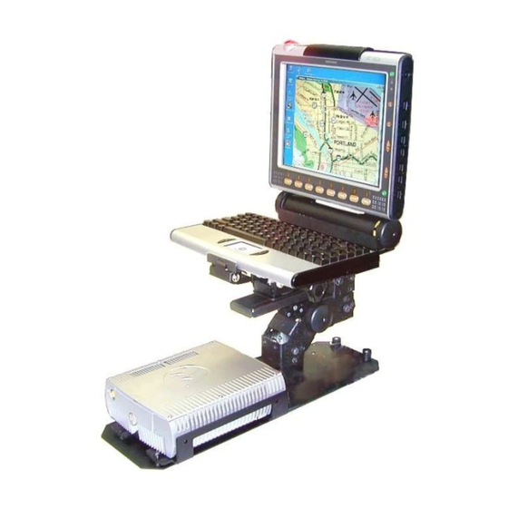
Motorola Mobile Workstation 800 Series Manuals
Manuals and User Guides for Motorola Mobile Workstation 800 Series. We have
3
Motorola Mobile Workstation 800 Series manuals available for free PDF download: Installation And Use Manual, Owner's Manual
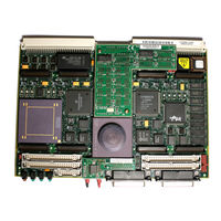
Motorola Mobile Workstation 800 Series Installation And Use Manual (156 pages)
Embedded Controller
Brand:
Motorola
| Category:
Controller
| Size: 0.37 MB
Table of Contents
Table of Contents
9
Chapter 1 Board Level Hardware Description
15
Introduction
15
Overview
15
Related Documentation
17
Documents for the MVME162LX
18
Other Applicable Motorola Publications
18
Applicable Non-Motorola Publications
19
Requirements
20
Features
20
Table 1-1. 700/800-Series MVME162LX: Features
20
Specifications
22
Table 1-2. 700/800-Series MVME162LX: Specifications
22
Cooling Requirements
23
Special Considerations for Elevated-Temperature Operation
23
FCC Compliance
25
Manual Terminology
25
Block Diagram
27
Functional Description
27
Front Panel Switches and Indicators
27
Figure 1-1. MVME162LX Block Diagram
28
Data Bus Structure
29
Microprocessor
29
MC68040 Cache
29
No-Vmebus-Interface Option
30
Memory Options
30
DRAM Options
30
SRAM Options
31
About the Battery
32
EPROM and Flash Memory
34
Battery Backed up RAM and Clock
34
Vmebus Interface and Vmechip2
34
I/O Interfaces
35
Serial Communications Interface
35
Industrypack (IP) Interfaces
36
Optional Ethernet Interface
36
Optional SCSI Interface
37
SCSI Termination
37
Local Resources
38
Programmable Tick Timers
38
Watchdog Timer
38
Software-Programmable Hardware Interrupts
39
Local Bus Timeout
39
Local Bus Arbiter
40
Connectors
40
Table 1-3. Local Bus Arbitration Priority
40
Memory Maps
41
Local Bus Memory Map
41
Normal Address Range
41
Table 1-4. Local Bus Memory Map
42
Table 1-5. Local I/O Devices Memory Map
44
Vmebus Memory Map
47
Vmebus Accesses to the Local Bus
47
Vmebus Short I/O Memory Map
47
Chapter 2 Hardware Preparation and Installation
49
Introduction
49
Unpacking Instructions
49
Hardware Preparation
49
Table 2-1. Jumper Settings
50
System Controller Select Header (J1)
51
Figure 2-1. MVME162LX Board Layout
52
IP Bus Clock Header (J11)
53
SCSI Terminator Enable Header (J12)
54
SRAM Backup Power Source Select Header (J14)
54
Flash Write Protect Header (J16)
55
IP Bus Strobe Select Header (J18)
56
IP DMA Snoop Control Header (J19)
56
Eprom/Flash Configuration Header (J20)
57
Table 2-2. J19 Snoop Control Encoding
57
Onboard Flash Disabled
58
Table 2-3. Eprom/Flash Mapping - 256K X 8 Eproms
59
Table 2-4. Eprom/Flash Mapping - 512K X 8 Eproms
59
Table 2-5. Eprom/Flash Mapping - 1M X 8 Eproms
59
General-Purpose Readable Jumpers Header (J21)
60
Table 2-6. Eprom/Flash Mapping - 1M X 8 Eproms
60
Memory Mezzanine Options
61
Installation Instructions
62
Table 2-7. Memory Mezzanine Stacking Options
62
IP Installation on the MVME162LX
63
MVME162LX Installation
64
System Considerations
66
Figure 2-2. DB-25 DTE-To-RJ-45 Adapter
68
Figure 2-3. DB-25 DCE-To-RJ-45 Adapter
68
Figure 2-4. Typical RJ-45 Serial Cable
69
Chapter 3 Debugger General Information
71
Overview of M68000 Firmware
71
Description of 162Bug
71
162Bug Implementation
73
Installation and Startup
73
Prom Versions
77
Autoboot
77
Romboot
79
Network Boot
80
Restarting the System
80
Reset
81
Abort
81
Break
82
SYSFAIL* Assertion/Negation
82
MPU Clock Speed Calculation
83
Memory Requirements
83
Disk I/O Support
85
Blocks Versus Sectors
85
Device Probe Function
86
Disk I/O Via 162Bug Commands
86
IOI (Input/Output Inquiry)
86
IOP (Physical I/O to Disk)
86
IOT (I/O Teach)
87
IOC (I/O Control)
87
BO (Bootstrap Operating System)
87
BH (Bootstrap and Halt)
87
Disk I/O Via 162Bug System Calls
87
Default 162Bug Controller and Device Parameters
89
Disk I/O Error Codes
89
Network I/O Support
89
Intel 82596 LAN Coprocessor Ethernet Driver
90
UDP/IP Protocol Modules
90
RARP/ARP Protocol Modules
91
BOOTP Protocol Module
91
TFTP Protocol Module
91
Network Boot Control Module
91
Network I/O Error Codes
92
Multiprocessor Support
92
Multiprocessor Control Register (MPCR) Method
92
GCSR Method
94
Diagnostic Facilities
95
Manufacturing Test Process
95
Chapter 4 Using the 162Bug Debugger
97
In this Chapter
97
Entering Debugger Command Lines
97
Terminal Input/Output Control
97
Debugger Command Syntax
99
Syntactic Variables
99
Expression as a Parameter
99
Address as a Parameter
101
Address Formats
102
Table 4-1. Debugger Address Parameter Formats
102
Offset Registers
103
Port Numbers
105
Entering and Debugging Programs
105
Creating a Program with the Assembler/Disassembler
106
Downloading an S-Record Object File
106
Read the Program from Disk
106
Calling System Utilities from User Programs
107
Preserving the Debugger Operating Environment
107
162Bug Vector Table and Workspace
108
Examples
108
Hardware Functions
109
Exception Vectors Used by 162Bug
109
Table 4-2. Exception Vectors Used by 162Bug
109
Exception Vector Tables
111
Using 162Bug Target Vector Table
111
Creating a New Vector Table
112
Floating Point Support
114
Single Precision Real
115
Double Precision Real
115
ScientifiC Notation
116
The 162Bug Debugger Command Set
116
Appendix A Configure and Environment Commands
117
Configure Board Information Block
117
Table 4-3. Debugger Commands
117
Set Environment to Bug/Operating System
123
Table A-1. ENV Command Parameters
124
Configuring the Industrypacks
134
Appendix B Disk/Tape Controller Data
139
Disk/Tape Controller Modules Supported
139
Disk/Tape Controller Default Configurations
140
IOT Command Parameters for Supported Floppy Types
143
Appendix C Network Controller Data
145
Network Controller Modules Supported
145
Appendix D Troubleshooting CPU Boards
147
Solving Startup Problems
147
Table D-1. Troubleshooting MVME162LX Boards
147
Advertisement
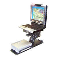
Motorola Mobile Workstation 800 Series Owner's Manual (62 pages)
Motorola Mobile Workstation 800 Series Owner's Manual Model F5207A, F5217A
Brand:
Motorola
| Category:
Desktop
| Size: 0.65 MB
Table of Contents
Table of Contents
3
Using this Manual
5
Who Should Use this Manual
5
Manual Introduction
5
Related Manuals
6
Conventions Used in this Manual
6
Getting Started
8
Section 1: Getting Started
8
What Is the CPU Box
8
Power on
9
Normal Operation
9
Low Temperature Conditions
10
High Temperature Conditions
10
Discharged Vehicle Battery
10
Section 2: Basic Operations
9
Shut down
10
Normal Operation
11
Extreme Shut down
11
Power Management
12
Standby
12
Resume
13
Resetting
13
Basic Operations
9
CPU Configuration Parameters
15
Section 3: CPU Configuration
15
BIOS Setup
18
CPU Configuration Change
18
Maintenance Programming Software
18
How to Modify Configuration Parameters
18
Figure 1. Main MPS Window
18
Figure 2. Codeplug Editor
19
CPU Configuration
15
CPU Manager
20
Figure 3. CPU Manager, Version Tab
20
Section 4: CPU Software
20
Figure 4. CPU Manager, Lines Control Tab
21
Figure 5. CPU Manager, Power Tab
21
Figure 6. CPU Manager, Temperature Tab
22
Figure 7. CPU Manager, Notifications Tab
23
Figure 8. CPU Manager, Logger Tab
23
MW800 Display Utilities
24
Calibration
24
Figure 9. Calibration Window
24
Extrakey Application
25
Figure 10. Extrakey Configuration
25
Display Tester
26
Volume Bar
26
CPU Software
20
Software/Firmware Upgrade
27
Description/Tutorial
27
OS and Drivers
27
Figure 11. Support Kit, Main Menu
27
Firmware Updates
28
Manual BIOS Update
28
Embedded CPU Firmware
29
Figure 12. EC Loader Setup
30
Figure 13. EC Loader Programming
30
Applications
31
Figure 14. Successful Programming
31
Manual CPU Manager Update
32
Manual Display Utilities Update
32
Recovery of Pre-Installed Software
33
Recovering Settings and System Files
33
Recovering Applications
33
Recovering the Hard Disk to Factory Contents from Recovery CD (Only for Windows 2000)
34
Hard Drive Replacement
34
Getting Assistance from Motorola
35
Appendix A: Safety Instructions
36
Appendix B: Warranty Information
38
Appendix C: FCC Information
41
Appendix D: Environment Specifications
42
Appendix E: CPU Features
43
Specifications
43
Features
43
Appendix F: Auxiliary Port Layout
46
Appendix G: Approved Accessories/Options
48
Appendix H: CPU Factory Default Setting
51
Appendix I: Differences between F5207A and F5217A
52
Appendix J: BIOS Factory Default Settings
53
Appendix K: Operating 2 Displays (F5207A Only)
54
Figure 15. Graphics Controller Properties (Extreme Driver)
55
Figure 16. Display Properties (Embedded Driver)
56
Figure 17. Graphics Controller Properties (Embedded Driver)
57
Appendix L: Troubleshooting
59
Table 6. Error Messages about Abnormal Conditions
59
Table 7. Failure Indications
59
Table 8. Failures Without Notification
60
Appendix M: Acronyms and Abbreviations
61
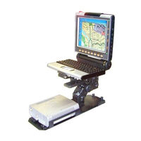
Motorola Mobile Workstation 800 Series Owner's Manual (33 pages)
Mobile Workstation Display Box
Brand:
Motorola
| Category:
Desktop
| Size: 0.35 MB
Table of Contents
Table of Contents
3
Using this Manual
5
Who Should Use this Manual
5
Manual Introduction
5
Related Manuals
5
Conventions Used in this Manual
6
Getting Started
7
What Is the Display Box
7
Section 1: Getting Started
7
Basic Operations
8
Power on
8
Normal Operation
8
Extreme Temperature Conditions
8
Discharged Vehicle Battery
8
Section 2: Basic Operations
8
Turn off
9
Normal Operation
9
Extreme Shut down
10
Power Management
10
Standby
10
Resume
10
Volume Adjustment
11
Brightness Adjustment
11
Emergency Key Operation
11
Function Key Operation
12
Figure 1. Extrakey Configuration
12
Touch Screen Calibration
13
Figure 2. Calibration Window
13
Display Configuration
14
Display Configuration Parameters
14
Section 3: Display Configuration
14
Display Configuration Change
16
Maintenance Programming Software
16
How to Modify Configuration Parameters
16
Figure 3. Main MPS Window
17
Figure 4. Codeplug Editor
17
Software/Firmware Upgrade
19
Description/Tutorial
19
Display Firmware Update
19
Figure 5. Support Kit, Main Menu
19
Automatic Firmware Update
20
Manual Firmware Update
20
Figure 6. EC Loader Setup
21
Figure 7. EC Loader Programming
21
Display Utilities Update
22
Automatic Display Utilities Update
22
Manual Display Utilities Update
22
Getting Assistance from Motorola
23
Appendix A: Safety Instructions
24
Appendix B: Warranty Information
26
Appendix C: FCC Information
29
Appendix D: Display Factory Setup
30
Appendix E: Troubleshooting
31
Table 2. Failure Indications
32
Appendix F: Acronyms and Abbreviations
33
Advertisement
Advertisement
Related Products
Motorola Mobile Workstation 800 F5207A
Motorola Mobile Workstation 800 F5217A
Motorola MW 800 F5206
Motorola MW 800 F5207
Motorola MW 800 F5217
Motorola 8000202590-A
Motorola APX 8000HXE
Motorola Escape 800 ANC
Motorola APX 8000HXE 1.5
Motorola APX 8000HXE 3.5
Motorola Categories
Cell Phone
Two-Way Radio
Baby Monitor
Cordless Telephone
Radio
More Motorola Manuals
Login
Sign In
OR
Sign in with Facebook
Sign in with Google
Upload manual
Upload from disk
Upload from URL