Sign In
Upload
Manuals
Brands
Mitsubishi Manuals
Touch terminals
A951GOT-SBD-M3
Mitsubishi A951GOT-SBD-M3 Manuals
Manuals and User Guides for Mitsubishi A951GOT-SBD-M3. We have
2
Mitsubishi A951GOT-SBD-M3 manuals available for free PDF download: User Manual
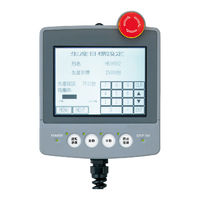
Mitsubishi A951GOT-SBD-M3 User Manual (126 pages)
Graphic Operation Terminal
Brand:
Mitsubishi
| Category:
Touch terminals
| Size: 7.03 MB
Table of Contents
Safety Precautions
4
Table of Contents
11
About the Manuals
14
Abbreviations and Generic Terms in this Manual
15
Packing List
17
1 Overview
18
Features
20
2 System Configuration
22
Overall Configuration
22
System Configuration of the GOT
24
Component List
24
Software Packages to be Used
30
Unusable Conventional Products
31
Notes on Q4ARCPU Duplex System
32
3 Performance
34
General Specifications
34
Performance Specifications
35
Power Supply Specifications
41
4 Names of the Parts and Their Settings
42
5 Rough Pre-Operation Procedure
44
6 Handling
46
GOT Main Unit
46
Handling Instructions
46
Installation Method
48
Wiring Method
50
Installation of Handy Type GOT
56
Protective Sheet
58
Mounting Procedure
58
Protective Sheet Type
58
Memory Board (A956WGOT Only)
59
Memory Board Types
59
Mounting Procedure
59
Memory Card Interface Module
60
Memory Card Interface Module Type
60
Mounting Procedure
60
Battery Changing Timing and Method
61
PC Card Types
61
Loading and Unloading Procedures
62
Compact Flash PC Card (A956WGOT Only)
63
Compact Flash PC Card Types
63
Loading and Unloading Procedures
64
Communication Board (A956WGOT Only)
65
Communication Board Types
65
Mounting Procedure
65
Communication Module (A956GOT, A956WGOT Only)
66
Connection Module Types
66
Mounting Procedure
67
Printer Interface Module
69
How to Connect the Printer Interface Module
69
Printer Interface Module Type
69
Connecting Procedure
70
Printer Types
70
External I/O Module
71
External I/O Module Type
71
Mounting Procedure
71
Bar Code Reader
72
Bar Code Reader Types
72
Connecting Procedure
72
Debug Stand
73
Debug Stand Type
73
Mounting Procedure
73
Attachment (A95*GOT Only)
74
Attachment Type
74
Mounting Procedure
74
7 Maintenance and Inspection
75
Instructions for Maintenance and Inspection
75
Daily Inspection
76
Periodic Inspection
76
How to Change the Backlight for Liquid Crystal
77
8 Emc Directive
79
Requirements for Conformance to EMC Directive
79
Standards Applicable to the EMC Directive
80
Control Cabinet
81
Grounding
82
System Configuration When EMC Directive Is Applicable
83
Overall Configuration
83
About Modules Applicable to the EMC Directive
84
Connection Format
85
When the Communication/Board Module Is Used
85
About the Cable Used
86
Method to Connect the Power Wire and Ground Wire
87
Wiring Precautions the Part Which Matches the EMC Directives
87
Grounding the Ground Cable
89
Grounding the Ground Cable
95
Grounding the Cable
97
9 ERROR CODES and ERROR MESSAGES 9 - 1 to
98
Definition of the Error Codes and Messages Displayed
98
Error Code and Error Message List
99
Precautions for Installation of ROM_BIOS
105
Troubleshooting in Bus Connection
106
Locating Error Positions
109
Further Locating Error Positions
111
Specific Example of Troubleshooting
112
Troubleshooting for Monitoring
113
Appendices
114
Appendix.1 Outline Dimension Drawings App
114
Appendix.2 Depth at the Time of Communication Module Loading (A956GOT/A956WGOT Only) App
116
Appendix.3 Outline Dimension Drawings of Bus Connection Cables App
120
Advertisement
Mitsubishi A951GOT-SBD-M3 User Manual (102 pages)
Graphic Operation Terminal
Brand:
Mitsubishi
| Category:
Touch terminals
| Size: 2.06 MB
Table of Contents
Safety Precautions
2
Table of Contents
8
About the Manuals
11
Packing List
14
1 Overview
15
Features
16
2 System Configuration
18
Overall Configuration
18
System Configuration of the GOT
20
Component List
20
Software Packages to be Used
24
Unusable Conventional Products
24
Notes on Q4ARCPU Duplex System
25
3 Performance
26
General Specifications
26
Performance Specifications
27
Power Supply Specifications
30
4 Names of the Parts and Their Settings
31
5 Rough Pre-Operation Procedure
33
6 Handling
35
GOT Main Unit
35
Handling Instructions
35
Installation Method
37
Wiring Method
38
Installation of Handy Type GOT
39
Protective Sheet
41
Protective Sheet Types
41
Mounting Procedure
41
Memory Board (A956WGOT Only)
42
Memory Board Types
42
Mounting Procedure
42
Memory Card Interface Module
43
Memory Card Interface Module Type
43
Mounting Procedure
43
PC Card Types
44
Battery Changing Timing and Method
44
Loading and Unloading Procedures
45
Compact Flash Card (A956WGOT Only)
46
Mounting Procedure
48
Communication Board (A956WGOT Only)
48
Communication Board Types
48
Communication Module (A956GOT, A956WGOT Only)
49
Connection Module Types
49
Mounting Procedure
50
Printer Interface Module
51
Printer Interface Module Type
51
How to Connect the Printer Interface Module
51
Printer Types
52
Connecting Procedure
52
External I/O Module
53
External I/O Module Type
53
Mounting Procedure
53
Bar Code Reader
54
Bar Cord Reader Types
54
Connecting Procedure
54
Debug Stand
55
Debug Stand Types
55
Mounting Procedure
56
Attachment (A95 GOT Only)
56
Attachment Type
56
7 Maintenance and Inspection
57
Instructions for Maintenance and Inspection
57
Daily Inspection
58
Periodic Inspection
58
How to Change the Backlight for Liquid Crystal
59
8 EMC Directive 8- 1 to
61
Requirements for Conformance to EMC Directive
61
Standards Applicable to the EMC Directive
62
Control Cabinet
63
Grounding
64
System Configuration When EMC Directive Is Applicable
65
Overall Configuration
65
Connection Format
65
About Models Applicable to the EMC Directive
66
About the Cable Used
67
Wiring Precautions the Part Which Matches the EMC Directives
68
Method to Connect the Power Wire and Ground Wire
68
Grounding the Ground Cable
69
Grounding the Cable
75
9 Error Codes and Error Messages
76
Definition of the Error Codes and Messages Displayed
76
Error Code and Error Message List
77
Precautions for Installation of ROM_BIOS
81
Troubleshooting in Bus Connection
84
Locating Error Positions
84
Further Locating Error Positions
89
Specific Example of Troubleshooting
90
Troubleshooting for Monitoring
91
Appendices
93
Appendix1 Outline Dimension Drawings
93
Appendix2 Depth at the Time of Communication Module Loading (A956GOT/A956WGOT Only)
95
Appendix3 Outline Dimension Drawings of Bus Connection Cables
99
Advertisement
Related Products
Mitsubishi A951GOT-SBD
Mitsubishi A951GOT-SBD-B
Mitsubishi A951GOT-SBD-M3-B
Mitsubishi A951GOT-QTBD
Mitsubishi A951GOT-QSBD
Mitsubishi A951GOT-QTBD-M3
Mitsubishi A951GOT-QSBD-M3
Mitsubishi A951GOT-LBD
Mitsubishi A951GOT
Mitsubishi A951GOT-LBD-M3
Mitsubishi Categories
Air Conditioner
Controller
Projector
Automobile
Engine
More Mitsubishi Manuals
Login
Sign In
OR
Sign in with Facebook
Sign in with Google
Upload manual
Upload from disk
Upload from URL