Sign In
Upload
Manuals
Brands
MGE UPS Systems Manuals
Switch
STS 600A
MGE UPS Systems STS 600A Manuals
Manuals and User Guides for MGE UPS Systems STS 600A. We have
3
MGE UPS Systems STS 600A manuals available for free PDF download: Installation And User Manual
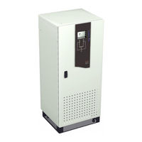
MGE UPS Systems STS 600A Installation And User Manual (66 pages)
Static Transfer Switch
Brand:
MGE UPS Systems
| Category:
Switch
| Size: 2.87 MB
Table of Contents
Revision History
3
Important Safety Instructions
4
Certification Standards
4
How to Use this Manual and Symbol Usage
5
CAUTION: Record All Serial Numbers
6
Table of Contents
7
Quick Start
11
First Steps by an On-Site Qualified Technical Engineer
11
Required Equipment and Tools
11
Step 1 Unpacking
12
QS-1 Positioning of 200A Epsilon STS™
12
QS-2 Positioning of 400/600A Epsilon STS™
13
Step 2 Connection of Utility Power Inputs
14
Connect Input Power from Two Sources
14
Step 3 Connection of the Load Outputs
14
200A Sts
14
Step 5 Arrival of MGE Field Engineer
15
QS-4 400/600A STS Input/Output Power Connections
15
Optional Steps
16
QS-5A 200A STS
16
QS-5B 400/600A STS
16
Introduction
17
Section Description
17
Scope
17
Reference Manuals
17
Section Descriptions
17
General Description
18
Epsilon STSTM System Characteristics
19
System Major Components
21
Operator Input Display
22
Single Line Diagram
23
System Specifications
24
Electrical Electrical Characteristics
24
Connecting Power Cables
25
Electrical Cable Access and Connections
25
Accessing Electrical Connections
26
Input/Output Power Connections
26
Input/Output Power Connections
27
STS Power and Control Wire Connections
27
Epilson STS
29
Setup and Installation
29
Scope
29
First Steps by an On-Site Qualified Technical Engineer
29
Required Equipment and Tools
29
Cabinet Placement and Environment
30
Clearances and Footprint
30
STS and 400/600A STS Cabinet Clearances
30
Conduit Plate Location (Bottom Entry)
31
Source #1 AC Input Connections
31
2.3.1. Source #2 AC Input Connections
31
AC Output Connections
31
400/600A Sts
31
A /400/600A STS Cabinet Footprint and Top View
31
Remote Emergency Power off (REPO) Cable Connections
32
Remote Source Loss Test Cable Connections
32
Control Connections
32
Connection of the Relay Communication Card
33
Characteristics of the Output Contacts
34
Characteristics of the Input Contacts
34
Output Contacts
34
Removing the Communications Card Cover
35
Replacing the Cover
35
Setting Operation Mode
36
SA2 and Dip Switch Location on Communication Card
36
Setting the Output Relay Contacts and Inputs Switching States
37
Check Points before and after Start up
38
Connection of the JBUS Communication Card
38
Post-Start up Safety Check List
38
Pre-Start up Safety Check List
38
JBUS Communication Card
38
Operation
39
Scope
39
Preparation for Operation
39
Pre-Start up Safety Check List
39
Normal Start up Procedure
40
Post Start up Safety Check List
41
Shutdown Procedure
41
Transfer Operations
42
Automatic Transfers
42
Manual Transfers
42
Automatic Retransfers
42
Transfer Authorization/Prohibition
43
Maintenance Bypass/Molded Case Switches/Live System Test
43
Switch Arrangement
43
Electrical Bypass Switch Interlock
43
Electric Input-Bypass Switch Interlock
43
Mechanical Key Interlocks
43
Live System Test (Except with 4-Interlock System)
44
Epo
44
Preferred Source Selection (Symmetrical Operation)
44
Sensing and Transfer Times
44
Overload Operation
44
Shorted SCR Protection (Including Backfeed Protection)
44
Open SCR Protection
45
Source Cross-Connection Protection
45
Bypass Procedure
45
Front Panel
47
Front Display Interface Panel
48
LCD Normal Operation Screen
49
Manual Operation Pushbuttons
50
LED MIMIC Diagram
51
Operator Interface Screens
52
LCD Display Screens
52
Epsilon STS™ Customization
53
Customization Screen
53
Customization Settings
53
Scenic Avenue Costa Mesa, CA
63
Advertisement
MGE UPS Systems STS 600A Installation And User Manual (30 pages)
Brand:
MGE UPS Systems
| Category:
UPS
| Size: 2.09 MB
Table of Contents
Table of Contents
5
Presentation
7
Upsilon STS 30 - 60 - 100 - 160 - 250 a (Cabinet 1400 MM High)
7
Upsilon STS 30 - 60 - 100 - 160 - 250 - 400 - 600 a (Cabinet 1900 MM High)
7
Access to Control and Connections
8
Upsilon STS 30 - 60 - 100 - 160 - 250 a (Cabinet 1400 MM High)
8
Upsilon STS 30 - 60 - 100 - 160 - 250 - 400 - 600 a (Cabinet 1900 MM High)
8
Man / Machine Interface
9
Relay Communication Card
10
Jbus Communication Card
10
Installation
11
Positioning
11
Upsilon STS 30 - 60 - 100 - 160 - 250 a (Cabinet 1400 MM High)
11
Upsilon STS 30 - 60 - 100 - 160 - 250 - 400 - 600 a (Cabinet 1900 MM High)
11
Power Connections
12
Upsilon STS 30 to 250 a with Input/Output: 3 Phases + PEN
12
Upsilon STS 30 to 250 a with Input: 3 Phases + PEN, Output: 3 Phases + PE + Neutral
12
Upsilon STS 30 to 250 a with Input/Output: 3 Phases + PE + Neutral
12
Upsilon STS 30 to 250 a with Input: 3 Phases + PEN, Output: 3 Phases + PE
13
Upsilon STS 30 to 250 a with Input/Output: 3 Phases + PE
13
Upsilon STS 400 to 600 a with Input/Output: 3 Phases + PE + Neutral
13
Upsilon STS 400 to 600 a with Input/Output: 3 Phases + PE
13
Upsilon STS 400 to 600 a with Input/Output: 3 Phases + PEN
14
Upsilon STS 400 to 600 a with Input: 3 Phases + PEN, Output: 3 Phases + PE + Neutral
14
Upsilon STS 400 to 600 a with Input: 3 Phases + PEN, Output: 3 Phases + PE
15
Cable Running for Cables Entering through the Top of the Upsilon STS 30 to 250 a Cabinet
16
Connection of the Emergency Power off Terminal Block
16
Connection of the Communication Cards
17
Connection of the JBUS Communication Card
17
Connection of the Relay Communication Card
18
Operation
19
Start-Up
19
Shutdown
19
Normal Mode: Operation on Preferred Source S1
20
Operation on the Preferred Source
20
Automatic Transfer to the Alternate Source
20
Manual Transfer to the Alternate Source
20
Manual Transfer to an Out-Of-Phase Alternate Source
21
Display Screens
22
Upsilon STS Customization
23
Customization of the Relay Communication Card
24
Maintenance
25
Identification of Anomalies
25
Transfer to the Manual Bypass
25
Environment
26
Appendix 6.1 Technical Data
27
Output Currents and Voltage
27
Thermal Characteristics
27
Noise Level
27
Cable Sizes
27
Recommended Protection Devices Upstream of Upsilon STS
27
Permissible-Overload Curve
27
Simplified Diagrams
28
Upsilon STS Simplified Diagram
28
Simplified Diagram of an Installation
28
Glossary
29
Index
30
MGE UPS Systems STS 600A Installation And User Manual (30 pages)
MGE UPS Systems Upsilon STS Installation and User Manual 30A, 60A, 100A, 160A , 250A, 400A, 600A
Brand:
MGE UPS Systems
| Category:
Power Supply
| Size: 2 MB
Advertisement
Advertisement
Related Products
MGE UPS Systems Epsilon STS 200A
MGE UPS Systems STS 400A
MGE UPS Systems Upsilon STS 60A
MGE UPS Systems Upsilon STS 100A
MGE UPS Systems Upsilon STS 160A
MGE UPS Systems Upsilon STS 250A
MGE UPS Systems Upsilon STS 800A
MGE UPS Systems Upsilon STS 1000A
MGE UPS Systems Upsilon STS 1200A
MGE UPS Systems Upsilon STS 900A
MGE UPS Systems Categories
UPS
Power Supply
Network Card
Power distribution unit
Medical Equipment
More MGE UPS Systems Manuals
Login
Sign In
OR
Sign in with Facebook
Sign in with Google
Upload manual
Upload from disk
Upload from URL