Sign In
Upload
Manuals
Brands
Kontron Manuals
Computer Hardware
CP3003-V
User Manuals: Kontron CP3003-V Industrial PC
Manuals and User Guides for Kontron CP3003-V Industrial PC. We have
2
Kontron CP3003-V Industrial PC manuals available for free PDF download: User Manual
Kontron CP3003-V User Manual (176 pages)
3U CompactPCI Processor Board
Brand:
Kontron
| Category:
PCI Card
| Size: 2 MB
Table of Contents
Preface
3
Imprint
2
Disclaimer
2
Table of Contents
3
Preface List of Tables
9
List of Tables
9
Preface List of Figures
15
List of Figures
15
Environmental Protection Statement
19
Proprietary Note
19
Trademarks
19
Explanation of Symbols
20
For Your Safety
21
High Voltage Safety Instructions
21
Special Handling and Unpacking Instructions
21
General Instructions on Usage
22
Two Year Warranty
23
Introduction
25
Board Overview
27
Board-Specific Information
27
System Expansion Capabilities
29
CP3003-HDD Module (8 HP and 12 HP)
29
CP3003-XMC Module (8 HP)
29
CP-RIO3-04 Rear I/O Module
29
SATA Flash Module
29
Smart Extension Module
29
Board Diagrams
29
Functional Block Diagram
30
CP3003-SA Functional Block Diagram
30
Front Panel
31
HP CP3003-SA Front Panel
31
Board Layout
32
HP CP3003-SA Board Layout (Top View)
32
HP CP3003-SA Board Layout (Bottom View)
32
Technical Specification
33
Standards
38
Related Publications
39
Additional Standards for Boards Ordered with Ruggedized Service
39
Features of the Processors Supported on the CP3003-SA
44
Watchdog and Temperature Status Leds Function
48
General Purpose Leds Function
49
POST Code Sequence
50
POST Code Example
50
DIP Switch SW1 Function
50
USB Connectors J5 and J6 Pinout
51
Maximum Resolution in 3-Display Configurations
51
USB Connectors J5 and J6
51
D-Sub VGA Connector J4 Pinout
52
D-Sub VGA Con. J4
52
SATA Connector J3 Pinout
54
SATA Con. J3
54
Compactpci Connector J1 System Controller Slot Pinout
58
Compactpci Connector J1 Peripheral Slot Pinout
59
Rear I/O Compactpci Connector J2 Pinout (CP3003-SA Rear I/O Vers.)
62
Rear I/O Signal Description
63
GPIO Signal Description
63
GPIO Signal Description
65
Gigabit Ethernet Signal Description
66
Ule
66
Power Supply and Power Management Signal Description
68
HP CP3003-SA with SATA Flash Module
76
HP CP3003-SA with CP3003-HDD Module
77
HP CP3003-SA with Smart Extension Module
77
12 HP CP3003-SA with CP3003-HDD Module and SATA Adapter Module
78
HP CP3003-SA with CP3003-XMC Module
78
Screws Securing the Front Panel and the CP3003-XMC to the CP3003-SA
81
Screws Securing the XMC Module to the CP3003-XMC Extension Module
81
CP3003-SA Board with CP3003-XMC Extension Module and XMC Module
82
CP3003-SA with Front Panel, CP3003-XMC Extension Module and XMC Mod
82
DIP Switch SW1 Functionality
89
DIP Switch SW1
89
I/O Address Map
90
Status Register 0 (STAT0)
91
Status Register 1 (STAT1)
92
Control Register 0 (CTRL0)
92
Control Register 1 (CTRL1)
93
Device Protection Register (DPROT)
94
Reset Status Register (RSTAT)
95
Board Interrupt Configuration Register (BICFG)
96
Status Register 2 (STAT2)
97
Board ID High Byte Register (BIDH)
97
Board and PLD Revision Register (BREV)
98
Geographic Addressing Register (GEOAD)
98
Board ID Low Byte Register (BIDL)
98
Watchdog Timer Control Register (WTIM)
100
LED Configuration Register (LCFG)
101
LED Control Register (LCTRL)
102
General Purpose Output Register (GPOUT)
103
General Purpose Input Register (GPIN)
104
Maximum Input Power Voltage Limits
107
DC Operational Input Voltage Ranges
107
Input Voltage Characteristics
109
CP3003-SA in EFI Shell
111
CP3003-SA with Win. 7 and Processor and Graphics in Idle State
111
CP3003-SA with Win. 7 and Max. Proc. Workload and Basic Graphics Operation
111
CP3003-SA with Win. 7 and Max. Processor and Graphics Workload
111
Power Consumption of CP3003-SA Accessories
112
XMC Module Current
112
CP3003-SA with I7-3612QE (SV), 2.1 Ghz
118
CP3003-SA with I7-3517UE (ULV), 1.7 Ghz
119
CP3003-HDD Module Specifications
123
CP3003-SA with I7-3555LE (LV), 2.5 Ghz
119
CP3003-HDD Module Functional Block Diagram
125
CP3003-HDD Module Layout for 12 HP Board Version (Top View)
127
CP3003-HDD Module Layout for 8 HP Board Version (Top View)
127
SATA Adapter for 2.5" SATA HDD/SSD (Top View)
128
Displayport Connectors J1 and J2 Pinout
129
Displayport Connectors J1 and J2
129
Gigabit Ethernet Connector J5 Pinout
130
Serial Port Connector J8
131
Cfast Connector J3 Pinout
132
Cfast Connector J3
132
SATA Connector J6/J2 Pinout
133
SATA Connector J6/J2
133
CP3003-XMC Module Specifications
137
USB Connector J7
131
CP3003-XMC Module Functional Block Diagram
138
Front Panel of the 8 HP CP3003-SA with CP3003-XMC Module
139
CP3003-XMC Module Layout (Bottom View)
140
Cfast Connector J2 Pinout
141
Cfast Connector J6
141
XMC Connector J1 Pinout
142
XMC Con. J1
142
CP-RIO3-04 Rear I/O Module Main Specifications
145
CP3003-XMC Module Layout (Top View)
140
CP-RIO3-04 Front Panels, 4 HP and 8 HP Versions
146
CP-RIO3-04 Rear I/O Module Layout, 4 HP Version
147
CP-RIO3-04 Rear I/O Module Layout, 8 HP Version
147
D-Sub VGA Connector J7 Pinout
148
D-Sub VGA Connector J7
148
Dual Gigabit Ethernet Connector J10A/B Pinout
149
Dual Gigabit Ethernet Connector J10A/B
149
COM Connectors J2A (COMA)
150
And J3A (COMB) Pinout C
150
COM Connectors J2A (COMA) and J3A (COMB)
150
Gigabit Ethernet
147
Peripheral Con. J13
151
Serial Port Connectors
151
Rear I/O Compactpci Connector Rj2
154
Rear I/O Signal Description
155
SATA Flash Module Specifications
159
SATA Flash Module Layout (Bottom View)
160
Smart Extension Module Specifications
163
SATA Flash Module Layout (Top View)
160
Smart Extension Module Layout (Bottom View)
164
Smart Extension Module Layout (Top View)
164
USB Connector J2
165
SATA Connector J1 Pinout
166
SATA Con. J1
166
CP3003-SA Vs. CP3003-V
170
Features of the Intel® Celeron® 807UE Processor
171
Maximum Resolution in 3-Display Configurations
171
CP3003-V Functional Block Diagram
172
Front Panel of the CP3003-V
173
CP3003-V in EFI Shell
175
CP3003-V with Win. 7 and Processor and Graphics in Idle State
175
CP3003-V with Win. 7 and Max. Processor and Graphics Workload
175
CP3003-V with Celeron® 807UE, 1.0 Ghz
176
Advertisement
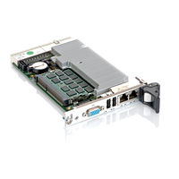
Kontron CP3003-V User Manual (72 pages)
uEFI BIOS
Brand:
Kontron
| Category:
Computer Hardware
| Size: 0 MB
Table of Contents
Imprint
2
Disclaimer
2
Revision History
2
Table of Contents
3
Starting Uefi BIOS Setup
9
Main Setup Menu
10
Navigation
11
Main Setup
13
Main Setup
15
BIOS Information
15
Memory Information
15
Trusted Computing
16
Configuration
16
TPM Support (CP3003-SA)
16
Current Status Information
16
CPU Configuration
17
Max Freq Ratio
17
Firmware Update Configuration
18
Me FW Image Re-Flash
18
USB Configuration
19
USB Devices
19
Legacy USB Support
19
USB3.0 Support
20
XHCI Hand-Off
20
EHCI Hand-Off
20
USB Hardware Delays and Time-Outs
21
USB Transfer Timeout
21
Device Reset Timeout
21
Device Power-Up Delay
21
Serial Port Console Redirection
22
Com0
22
Console Redirection
22
Console Redirection Settings
22
Com1
23
Console Redirection
23
Console Redirection Settings
23
Serial Port for Out-Of-Band Management/Windows EMS
26
Console Redirection
26
Console Redirection Settings
26
System Language
28
System Date
28
System Time
28
Access Level
28
Boot Setup
31
Boot Configuration
31
Setup Prompt Timeout
31
Bootup Numlock State
31
Quiet Boot
32
Fast Boot
32
CSM16 Module Version
32
Gatea20 Active
32
Option ROM Messages
32
Interrupt 19 Capture
33
CSM Support
33
Boot Option Priorities
33
Boot Option #1..2
33
Hard Drive BBS Priorities
33
Security Setup
35
Security Setup
37
Administrator Password
38
User Password
38
HDD Security Configuration
38
Remember the Password
38
Save & Exit
41
Save Changes and Exit
41
Discard Changes and Exit
41
Save Changes and Reset
41
Discard Changes and Reset
42
Save Changes (Save Options)
42
Discard Changes (Save Options)
42
Restore Defaults (Save Options)
42
Save as User Defaults (Save Options)
42
Restore User Defaults (Save Options)
42
Boot Override
42
The Uefi Shell
45
Introduction, Basic Operation
45
Shell Startup
45
Kontron-Specific Uefi Shell Commands
46
Kbiosrevision Uefi Shell Command
47
Kboardconfig Uefi Shell Command
48
Kboardinfo Uefi Shell Command
55
Kboot Uefi Shell Command
57
Kbootnsh Uefi Shell Command
58
Kclearnvram Uefi Shell Command
59
Kflash Uefi Shell Command
60
Kmkramdisk Uefi Shell Command
61
Kpassword Uefi Shell Command
62
Kresetconfig Uefi Shell Command
63
Ksettings Uefi Shell Command
64
Kwdt Uefi Shell Command
65
Uefi Shell Scripting
66
Startup Scripting
66
Create a Startup Script
66
Examples of Startup Scripts
66
Automatic Booting from USB Flash Drive
66
Execute Shell Script on Other Harddrive
67
Enable Watchdog and Control PXE Boot
67
Handling the Startup Script in the Flash Bank
68
Updating the Uefi BIOS
71
Uefi BIOS Fail-Over Mechanism
71
Updating Procedure
71
Uefi BIOS Recovery
71
Determining the Active Flash
71
Advertisement
Related Products
Kontron CP308
Kontron CP3002-RA
Kontron CP3002-RC
Kontron CP3003-SA
Kontron CP3002
Kontron CP3005-SA
Kontron CP3-BP4-M
Kontron CP3-BP6-ATX
Kontron CP3-BP11-P47
Kontron CP3-BP11-M
Kontron Categories
Computer Hardware
Motherboard
Server
Industrial PC
Desktop
More Kontron Manuals
Login
Sign In
OR
Sign in with Facebook
Sign in with Google
Upload manual
Upload from disk
Upload from URL