Sign In
Upload
Manuals
Brands
Keysight Technologies Manuals
Measuring Instruments
N5225A
Keysight Technologies N5225A Manuals
Manuals and User Guides for Keysight Technologies N5225A. We have
2
Keysight Technologies N5225A manuals available for free PDF download: Service Manual, Configuration Manual
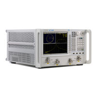
Keysight Technologies N5225A Service Manual (362 pages)
2-Port and 4-Port PNA Microwave Network Analyzers, 10 MHz to 43.5 / 50 GHz
Brand:
Keysight Technologies
| Category:
Measuring Instruments
| Size: 12.43 MB
Table of Contents
Safety Notices
2
Table of Contents
3
Safety and Regulatory Information
9
Information in this Chapter
9
Chapter One At-A-Glance
9
Safety Symbols
10
General Safety Considerations
11
Safety Earth Ground
11
Before Applying Power
11
Servicing
13
Electrostatic Discharge Protection
15
Regulatory Information
17
Instrument Markings
17
Lithium Battery Disposal
18
General Product Information
19
Information in this Chapter
19
Chapter Two At-A-Glance
19
Maintenance
20
Physical Maintenance
20
Electrical Maintenance
20
Analyzer Options, Accessories, and Upgrades Available
21
Pulse I/O Adapter-N1966A
21
Required Service Test Equipment
22
Keysight Support, Services, and Assistance
25
Service and Support Options
25
Contacting Keysight
25
Shipping Your Analyzer to Keysight for Service or Repair
26
Tests and Adjustments
27
Information in this Chapter
27
Conventions Used for Hardkeys, Softkeys, and Menu Items
27
Chapter Three At-A-Glance
27
Before You Begin
30
Verify the Operating Environment
30
Protect against Electrostatic Discharge (ESD)
30
Allow the Analyzer to Warm up
31
Review the Principles of Connector Care
31
About System Verification and Performance Tests
33
System Specifications
33
Instrument Specifications
34
System Verification Procedure
34
Performance Tests
34
Certificate of Calibration
35
ANSI/NCSL Z540.3-2006 and ISO/IEC 17025 Verification
36
Non-Standards Compliant Verification
37
Preliminary Checks
38
The Operator's Check
38
The Test Port Cable Checks
40
System Verification
47
What the System Verification Verifies
47
Measurement Uncertainty
47
Measurement Traceability
48
Performing System Verification
49
Performance Tests
57
Source Power Accuracy Test
57
Source Maximum Power Output Test
58
Source Power Linearity Test
59
Frequency Accuracy Test
60
Trace Noise Test
60
Receiver Compression Test
61
Noise Floor Test
63
Calibration Coefficients Test
64
Dynamic Accuracy Test
65
Adjustments
67
10 Mhz Frequency Reference Adjustment
67
Synthesizer Bandwidth Adjustment
68
Source Adjustment
68
IF Gain Adjustment
69
Receiver Characterization
69
Receiver Adjustment
70
EE Default Adjustment
72
IF Response Adjustment (Option 090, 093, or 094 Only)
72
Troubleshooting
73
Information in this Chapter
73
Chapter Four At-A-Glance
74
Conventions Used for Hardkeys, Softkeys, and Menu Items
74
Operating the Analyzer with Covers Removed
75
Protect against Electrostatic Discharge (ESD)
76
Assembly Replacement Sequence
77
Keysight N5224A/25A Service Guide
77
Getting Started with Troubleshooting
78
Check the Basics
78
Troubleshooting Organization
78
Power up Troubleshooting
80
Power Supply Check
81
Troubleshooting LCD Display Problems
86
Front Panel Troubleshooting
88
Front Panel Keypad and RPG Test
88
A3 Display Test
91
Checking the A2 USB Board
91
A1 Front Panel Interface Board
92
Rear Panel Troubleshooting
93
Checking the USB Ports
93
Checking the CONTROLLER Port
93
LAN Troubleshooting
94
Measurement System Troubleshooting
100
Before You Begin-Consider: Where Do You See a Problem
100
Verifying the A, B, C, D, and R Traces (Standard S-Parameter Mode)
101
Where to Begin Troubleshooting
103
Checking the Source Group
106
Checking the Signal Separation Group
111
Checking the Receiver Group
115
Instrument Block Diagrams Sheet 1
120
Microwave PNA, N522Xa
120
Instrument Block Diagrams Sheet 2
122
Microwave PNA, N522Xa
122
Theory of Operation
125
Information in this Chapter
125
Chapter Five At-A-Glance
125
Network Analyzer System Operation
126
Functional Groups of the Network Analyzer
127
Synthesized Source Group Operation
130
Basic Operation
130
A4, A15, and A17 13.5 Ghz Synthesizer Boards
134
A5 and A10 26.5 Ghz Source Boards
135
A7, A8, A12, and A13 50 Ghz Doubler Boards
135
A25 Multiplier/Amplifier 26.5 Board (HMA26.5)
136
A14 Frequency Reference Board
136
A23 Test Set Motherboard
137
Signal Separation Group Operation
141
Configurable Test Set
141
A29-A32 Receiver Couplers
142
A33-A36 Test Port Couplers
142
A38-A41 60-Db Source Step Attenuators and A42-A45 Bias Tees
143
Receiver Group Operation
146
A46-A49 35-Db Receiver Step Attenuators
146
A37 Reference Mixer Switch
146
A27 and A28 Mixer Bricks
146
A16 SPAM Board (Analog Description)
147
A24 if Multiplexer Board
147
Digital Processing and Digital Control Group Operation
151
Front Panel Subgroup
153
Data Acquisition and Processing Subgroup
154
Power Supply Group Operation
156
Replaceable Parts
157
Information in this Chapter
157
Chapter Six At-A-Glance
157
Ordering Information
158
Assembly Replacement Sequence
159
Rebuilt-Exchange Assemblies
160
Replaceable Parts Listings
162
Front Panel Assembly, Front Side, All Options
166
Front Panel Assembly, Back Side, All Options
168
Top Assemblies and Cables, All Options
172
Port Configuration, Option 200
178
Port Configuration, Option 201
184
Port Configuration, Option 210
190
Port Configuration, Option 217
196
Port Configuration, Option 219
203
Port Configuration, Option 400
210
Port Configuration, Option 401
217
Port Configuration, Option 410
224
Port Configuration, Option 417
231
Port Configuration, Option 419
240
Rear Panel Assembly, All Options
250
Fan Assemblies, All Options
252
Top Hardware and Miscellaneous Parts, All Options
254
Bottom Hardware and Miscellaneous Parts
256
Internal Hardware and Miscellaneous Parts, All Options
259
External Hardware and Miscellaneous Parts, All Options
261
Information in this Chapter
267
Personal Safety Warnings
268
Electrostatic Discharge (ESD) Protection
269
Removal and Replacement Procedures
270
Removing the Covers
272
Removing and Replacing the Front Panel Assembly
274
Removing and Replacing the A1–A3 and Other Front Panel Subassemblies
276
Removing and Replacing the A4–A17 Boards
280
Removing and Replacing the A18 System Motherboard
283
Removing and Replacing the A19 Midplane Board
286
Removing and Replacing the A20 Power Supply Assembly
288
Removing and Replacing the A21 CPU Board Assembly
290
Removing and Replacing the A22 GPIB Board
292
Removing and Replacing the A23 Test Set Motherboard
294
Removing and Replacing the A24 if Multiplexer Board
296
Removing and Replacing the A25 HMA26.5
298
Removing and Replacing the A26 Splitter
300
Removing and Replacing the A27 and A28 Mixer Bricks
302
Brackets
304
Removing and Replacing the A33–A36 Test Port Couplers
306
Removing and Replacing the A37 Reference Mixer Switch
309
Attenuators
311
Removing and Replacing the A42–A45 Bias Tees
313
Removing and Replacing the A55 Solid State Drive (SSD)
315
Removing and Replacing the Rear Panel
317
Removing and Replacing the Front Panel LED Boards
319
Removing and Replacing the Fans
321
Removing and Replacing the Lithium Battery
323
Post-Repair Procedures
325
Information in this Chapter
329
Error Terms
330
Performing Measurement Calibration
331
Accessing Error Terms
334
Error Term Data
336
Option Enable Utility
339
Enabling or Removing Options
340
Repairing and Recovering Option Data
341
Installing or Changing a Serial Number
342
Firmware Upgrades
343
Operating System Recovery
344
Correction Constants
345
Advertisement
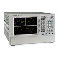
Keysight Technologies N5225A Configuration Manual (36 pages)
PNA-X Series PNA Series PNA-L Series N522x/3x/4xA Microwave Network Analyzers
Brand:
Keysight Technologies
| Category:
Measuring Instruments
| Size: 3.69 MB
Table of Contents
Network Analyzers
1
Table of Contents
2
PNA Family Network Analyzer Configurations
5
Test Set and Power Configuration Options
5
Application Options
6
Accessories, Calibration Options
7
PNA-X Series Test Set and Power Configuration Options
8
PNA Series Test Set and Power Configuration Options
10
PNA-L Series Test Set and Power Configuration Options
12
PNA Family Application Options
13
Measurement Applications
13
Noise Figure Options
16
PNA-X Block Diagrams with Noise Figure Option
17
Noise Figure Options Summary
18
Pulse, Antenna, MM-Wave
19
Accessories
20
PNA Family Network Analyzer Upgrade Kits
21
Frequency, Test Ports, Test Set and Power Configurations
21
Application Options
22
Upgrade Paths
24
Applications
25
Material Measurements
25
Signal Integrity Measurements
25
Multiport Measurements
25
Millimeter-Wave Measurements
25
Cables and Adapter Sets
27
Calibration Kits
27
For Devices with 1.0 MM Connectors
28
For Devices with 1.85 MM Connectors
28
For Devices with 2.4 MM Connectors
29
For Devices with K (2.92 MM) Connectors
29
For Devices with 3.5 MM, SMA, or 2.92 MM Connectors
30
For Devices with 3.5 MM or SMA Connectors
31
For Devices with Type-N Connectors
33
For Devices with 7 MM Connectors
34
For Devices with Waveguide
34
Verification Kits
35
Measurement Accessories
27
General Accessories
35
Spare Drive
35
Probe
36
Power Meters and Sensors
36
Comb Generators
36
Amplifiers
36
Couplers
36
Equipment Rack Accessories
36
Monitors
36
Interface Cables
36
Advertisement
Related Products
Keysight Technologies N5224A
Keysight Technologies N5221A
Keysight Technologies N5222A
Keysight Technologies N5227A
Keysight Technologies N5222B
Keysight Technologies N5227B
Keysight Technologies N5221B
Keysight Technologies N5221BU
Keysight Technologies N5222BU
Keysight Technologies N5221BU- 661
Keysight Technologies Categories
Measuring Instruments
Test Equipment
Control Unit
Portable Generator
Power Supply
More Keysight Technologies Manuals
Login
Sign In
OR
Sign in with Facebook
Sign in with Google
Upload manual
Upload from disk
Upload from URL