Sign In
Upload
Manuals
Brands
Keysight Technologies Manuals
Measuring Instruments
N5227B
Keysight Technologies N5227B Manuals
Manuals and User Guides for Keysight Technologies N5227B. We have
2
Keysight Technologies N5227B manuals available for free PDF download: Service Manual, Installation Notes
Keysight Technologies N5227B Service Manual (226 pages)
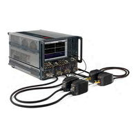
2-Port and 4-Port Microwave Network Analyzer System (900 Hz - 110 GHz / 900 Hz - 120 GHz)
Brand:
Keysight Technologies
| Category:
Measuring Instruments
| Size: 6 MB
Table of Contents
Table of Contents
5
1 Safety and Regulatory Information
11
Information in this Chapter
11
Chapter One At-A-Glance
11
Safety Symbols
12
General Safety Considerations
13
Safety Earth Ground
13
Before Applying Power
13
Servicing
15
Electrostatic Discharge Protection
17
ESD Equipment Required for the Installation
18
Regulatory Information
19
Instrument Markings
19
Lithium Battery Disposal
20
EMC and Safety Information
20
N5292A Test Set Equipment Ratings
22
Environmental Requirements
23
System Heating and Cooling
24
Required Conditions for Accuracy Enhanced Measurement
24
Space Requirements
25
N5290/1A System Weight and Dimensions
25
Component Weight and Dimensions
25
Site Preparation
27
Power Requirements
27
2 General Product Information
29
Information in this Chapter
29
Chapter Two At-A-Glance
29
N5290/1A System Options, Accessories, and Upgrades Available
31
Required Service Test Equipment
31
Keysight Support, Services, and Assistance
34
Service and Support Options
34
Contacting Keysight
35
Shipping an Item to Keysight for Service or Repair
35
Product Selection and Configuration Assistance, Education and Training
36
3 System Tests and Adjustments
37
Information in this Chapter
37
Chapter Three At-A-Glance
38
Before You Begin
39
Verify the Operating Environment
39
Torquing Connections
40
Long Term Storage of Test Results
40
Protect against Electrostatic Discharge (ESD)
41
Review the Principles of Connector Care
41
ANSI/NCSL Z540.3-2006 and ISO/IEC 17025 Verification
43
Non-Standards Compliant Verification
43
The N5290/1A Millimeter Test System Preliminary Check
43
N5290/1A Incoming Electrical Inspection
44
N5292A Functional Verification Procedure
52
Initial Setup for the N5292A Test Set Functional Verification
52
Performing the N5292A Test Set Functional Verification
59
N5290/1A Millimeter-Wave Test System Operator's Check
77
Performing the N5290/1 a System Operator's Check
77
If the N5290/1A Operator's Check Fails
80
Test Management Environment (TME) Performance Tests (N5290/1 a Millimeter System Only)
81
Guidelines for Ordering Power-Sensor Calibration Service
81
Adjustments
83
LO Adjustment for MM Mode
85
IF Gain Adj for MM Mode
85
Source and Receiver Adj
85
Receiver Characterization
85
IF Response Adj. for MM Mode
85
4 N5290/91A Troubleshooting
87
Information in this Chapter
87
Chapter Four At-A-Glance
88
Getting Started with Troubleshooting
89
Troubleshooting Organization
89
N5290/1A Millimeter-Wave System Troubleshooting
91
N5292A Test Controller Troubleshooting
92
Power Supplies and Fans
92
No DC Power for Millimeter-Wave Modules
94
Procedure for Identifying a Faulty Millimeter Head
94
Verifying the A5 Test Set Motherboard (TSMB)
94
Verifying the A1 Power Supply
103
Verifying the A2 LOPA, A3 LODA, and A4 Phase Compensation Boards
108
Head Stability Check
111
Front Panel Active LED
113
RF out Failures
113
LO out Failure
113
REF if or Test if
114
Test Set Diagrams and Graphics
115
5 Theory of Operation
119
Information in this Chapter
119
Chapter Seven At-A-Glance
120
Theory of Operation
121
Overview
121
LO Behavior Without LFE (Low Frequency Extension)
121
LO Behavior with Low Frequency Extension (LFE) Operation
121
10 Mhz to 19 Ghz Operation
122
DC Power
122
Overview - N5292A Test Set
123
System Level Block Diagrams
124
6 Replaceable Parts
129
Information in this Chapter
130
Chapter Six At-A-Glance
131
Ordering Information
132
Assembly Replacement Sequence
133
Replaceable Parts Listings
134
Front Panel Assembly, Front Side, All Options
137
Front Panel Assembly, Back Side, All Options
141
Top Assemblies and Cables, All Options
146
Top Assemblies, All Options
146
Top Cables, All Cables, All Options
147
Bottom Assemblies and Cables, All Options by Option Set
149
N5292A 2-Port Configuration, Option 200
149
N5292A 4-Port Configuration, Option 400
154
Rear-Panel Assembly, All Options
160
Fan Assemblies, All Options
161
Top Hardware and Miscellaneous Parts, All Options
163
Bottom Hardware and Miscellaneous Parts, All Options
164
Internal Hardware and Miscellaneous Parts, All Options
168
External Hardware and Miscellaneous Parts, All Options
170
Miscellaneous Part Numbers
171
Replaceable Parts
173
7 Repair and Replacement Procedures
177
Information in this Chapter
177
Chapter Seven At-A-Glance
178
Personal Safety Warnings
179
Electrostatic Discharge (ESD) Protection
180
Removal and Replacement Procedures
181
Removing the N5292A Option 200/400 from the System
182
Removing the Cover
184
Removing and Replacing the Front Panel and Subpanel Assemblies
186
Removing and Replacing the A2-A4 Boards
190
Removing and Replacing the A5 Test-Set Motherboard
196
Removing and Replacing the A1 Power Supply Assembly
200
Removing and Replacing the Rear Panel
202
Removing and Replacing the Front Panel Power Switch Board
204
Removing and Replacing the Subpanel PCA Sensor Boards
205
Removing and Replacing the Front Panel Integrated Connectors/Cables
207
Removing and Replacing the Fans
209
Post-Repair Procedures
212
8 General Purpose Maintenance Procedures
215
Information in this Chapter
216
Chapter Eight At-A-Glance
216
Maintenance
217
Physical Maintenance
217
Electrical Maintenance
217
Error Terms
217
Keysight License Manager
218
Accessing the Keysight License Manager
218
Software Entitlement Certificate
218
Enabling or Removing Options
219
Repairing and Recovering Option Data
220
Installing or Changing a Serial Number
220
Firmware Upgrades
221
How to Check the Current Firmware Version
221
Downloading from the Internet
221
Operating System Recovery
222
Advertisement
Keysight Technologies N5227B Installation Notes (42 pages)
4-Port PNA Direct Digital Synthesizer DDS For Version 7 Dual-Source Synthesizer Upgrade Kit
Brand:
Keysight Technologies
| Category:
Measuring Instruments
| Size: 2 MB
Table of Contents
Safety Notices
2
Getting Assistance from Keysight
4
Contacting Keysight
4
Getting Prepared
5
Tools Required for the Installation
7
Table of Contents
10
Overview of the Installation Procedure
10
Step 1. Verify PNA and Erase Flash
11
Step 2. Remove the Inner and Outer Covers
13
Step 3. Remove some Cables (All Models) and some Bottom Assemblies (Options 405, 420, and 425 Only)
13
Step 4. Remove some Top Cables
17
Step 5. Remove the Left and Right Inner Bracket's #4 Card Guides
19
Step 6. Install the Center Bracket
20
Step 7. Reinstall Bottom Cables
21
Step 8. Reinstall Top Assemblies Reinstall the A5 through A16
22
Direct Digital Synthesis (DDS) Assembly) and Cables
22
Step 9. Install *NEW* A15 Direct Digital Synthesizer (DDS) Assembly"
23
Step 10. Install *NEW* and Reused Direct Digital Synthesis (DDS) Assembly Cables
25
Step 11. Route Gray Cables
30
Step 12. Add Back Plate and Cable to Rear Panel (Option 422/423 with and Without 029 Only)
32
Step 13. Install "SRC3 J13" Label on Rear Panel (Option 422/423 with and Without Option 029 Only)
34
Step 14. Remove and Replace the A55 Solid State Drive (SSD)
34
Step 15. Boot the Instrument
35
Step 16. Reinstall the Inner and Outer Covers
35
Step 17. Verify the PNA Analyzer Program Is Running with the Correct Options
35
Step 18. Perform Post-Upgrade Adjustments and Calibration
36
Advertisement
Related Products
Keysight Technologies N5227A
Keysight Technologies N5224A
Keysight Technologies N5221A
Keysight Technologies N5222A
Keysight Technologies N5222B
Keysight Technologies N5221B
Keysight Technologies N5222BU- 661
Keysight Technologies N5222-60127
Keysight Technologies N5224/5A
Keysight Technologies N5221/2A Series
Keysight Technologies Categories
Measuring Instruments
Test Equipment
Control Unit
Portable Generator
Power Supply
More Keysight Technologies Manuals
Login
Sign In
OR
Sign in with Facebook
Sign in with Google
Upload manual
Upload from disk
Upload from URL