Keithley 2520 Manuals
Manuals and User Guides for Keithley 2520. We have 3 Keithley 2520 manuals available for free PDF download: User Manual, Service Manual, Quick Reference Manual
Keithley 2520 User Manual (329 pages)
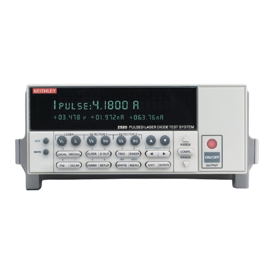
Pulsed Laser Diode Test System
Brand: Keithley
|
Category: Test Equipment
|
Size: 5 MB
Table of Contents
-
Connections
29 -
-
-
Polarity66
-
Pulse Mode71
-
-
Data Flow94
-
-
Sweep Operation
106 -
-
Sweep Types107
-
Table113
-
Triggering
117 -
8 Triggering
121-
-
Output Trigger129
-
-
Table130
-
-
-
GPIB Operation142
-
Table145
-
-
Query Commands151
-
Short-Form Rules152
-
-
Status Structure
160-
Overview161
-
-
-
Common Commands
181 -
-
Reference Tables191
-
Table192
-
Table194
-
Table195
-
Table196
-
Output Subsystem216
-
-
-
Source Subsystem221
-
-
Set Amplitudes223
-
-
Set Pulse Times225
-
Configure Sweeps226
-
Center <N>227
-
STEP <N>228
-
Points <N>229
-
Configure List230
-
Points?231
-
Delay <Nrf List>232
-
Set Amplitudes236
-
Setting Bit Size237
-
-
Status Subsystem238
-
Enable <List>240
-
Posetup241
-
Count?242
-
-
RS-232 Interface244
-
Trace Subsystem245
-
-
Timer <N>248
-
Iline <Nrf>249
-
Introduction255
-
-
-
-
-
Introduction263
-
-
Introduction267
-
Bus Lines270
-
-
-
-
Offset Currents303
-
Voltage Burden304
-
Light305
-
Introduction309
-
Bus Hold-Off311
-
Introduction313
-
Advertisement

Keithley 2520 Service Manual (137 pages)
Pulsed Laser Diode Test System
Brand: Keithley
|
Category: Test Equipment
|
Size: 3 MB
Table of Contents
-
-
Introduction14
-
-
-
Introduction32
-
-
-
-
Introduction74
-
-
KEYS Test75
-
-
-
-
Introduction92
-
-
-
Introduction100
-
Parts Lists100
-
Factory Service100
-
Specifications
117-
-
Source Accuracy120
-
-
-
Introduction122
-
Command Summary122
-
-

Keithley 2520 Quick Reference Manual (37 pages)
Pulsed Laser Diode Test System
Brand: Keithley
|
Category: Measuring Instruments
|
Size: 1 MB
Table of Contents
-
Introduction10
-
Figure 212
-
-
-
Table35
Advertisement