
Related Manuals for Keithley 2520


Summary of Contents for Keithley 2520
- Page 1 Model 2520 Pulsed Laser Diode Test System Quick Reference Guide A G R E A T E R M E A S U R E O F C O N F I D E N C E...
- Page 2 WARRANTY Keithley Instruments, Inc. warrants this product to be free from defects in material and workmanship for a period of 1 year from date of shipment. Keithley Instruments, Inc. warrants the following items for 90 days from the date of shipment: probes, cables, rechargeable batteries, diskettes, and documentation.
- Page 3 Model 2520 Pulsed Laser Diode Test System Quick Reference Guide ©2001, Keithley Instruments, Inc. All rights reserved. Cleveland, Ohio, U.S.A. Second Printing, March 2003 Document Number: 2520-903-01 Rev. B...
- Page 4 Revision A (Document Number 2520-903-01) ..............June 2001 Revision B (Document Number 2520-903-01) .............. March 2003 All Keithley product names are trademarks or registered trademarks of Keithley Instruments, Inc. Other brand names are trademarks or registered trademarks of their respective holders.
- Page 5 Keithley products are designed for use with electrical signals that are rated Installation Category I and Installation Category II, as described in the International Electrotechnical Commission (IEC) Standard IEC 60664. Most measurement, control, and data I/O signals are Installation Category I and must not be directly connected to mains voltage or to voltage sources with high tran- sient over-voltages.
- Page 6 To maintain protection from electric shock and fire, replacement components in mains circuits, including the power transformer, test leads, and input jacks, must be purchased from Keithley Instruments. Standard fuses, with applicable national safety ap- provals, may be used if the rating and type are the same. Other components that are not safety related may be purchased from other suppliers as long as they are equivalent to the original component.
-
Page 7: Table Of Contents
Table of Contents Introduction ................Source and measure capabilities ..........Front and rear panels ..............Navigating menus and entering numeric data ......Menu navigation ..............Numeric data entry (EDIT keys) ......... Editing source values ..............Editing keys ................ Configuring laser diode source ........... Setting photodiode detector source values ...... - Page 8 List of Illustrations Figure 1 Mainframe front panel ............Figure 2 Mainframe rear panel ............. Figure 3 Testhead front panel ............... Figure 4 Testhead rear panel ..............Figure 5 Testhead connections .............. Figure 6 Remote interlock connections ..........1-10 Figure 7 Laser diode test connections ..........
- Page 9 List of Tables Table 1 SCPI commands for selecting polarity ........ 1-12 Table 2 Basic operating procedure ........... 1-13 Table 3 SCPI commands for basic laser diode tests ......1-14 Table 4 Basic laser diode test programming example ...... 1-15 Table 5 Filter commands ..............
-
Page 10: Introduction
This guide is designed to familiarize users with fundamental operation (front panel and remote) of the Keithley Model 2520 Pulsed Laser Diode Test System. For comprehensive information on all aspects of Model 2520 operation, refer to the Model 2520 User’s Manual. -
Page 11: Source And Measure Capabilities
Measure current on each of two channels from 0.7µA to 105mA. • Maximum current for each bias source is 100mA. Front and rear panels The front and rear panels of the Model 2520 mainframe and testhead are shown in Figure Figure Figure... -
Page 12: Figure 2
Quick Reference Guide Figure 2 Mainframe rear panel WARNING: NO INTERNAL OPERATOR SERVICABLE PARTS, SERVICE BY QUALIFIED PERSONNEL ONLY. IEEE-488 CAT I MADE IN (CHANGE IEEE ADDRESS U.S.A. WITH FRONT PANEL MENU) PULSE DIGITAL I/O SYNC RS-232 TRIGGER LINK TESTHEAD CONN 1 LINE FUSE SLOWBLOW... -
Page 13: Navigating Menus And Entering Numeric Data
Navigating menus and entering numeric data Menu navigation Many operating modes for the Model 2520 are configured using front panel menus. Throughout this guide, menu navigation will be presented as a sequence of key presses and menu item selections. For example, the following sequence selects the current source pulse mode: Press CONFIG >... -
Page 14: Numeric Data Entry (Edit Keys)
Quick Reference Guide Numeric data entry (EDIT keys) Numeric values must be entered for some menu items. Numeric entry is also used to set source and compliance values. The edit keys for numeric entry include the EDIT keys to control cursor position, EDIT keys to increment or decrement the digit value, and the number keys. -
Page 15: Setting Photodiode Detector Source Values
Quick Reference Guide If you chose the PULSE mode, set the following: Select LOW, then press ENTER. Set the pulse low amplitude to the desired value, then press ENTER. Press EXIT to return to normal display. Press the PW key, then set the pulse width to the desired value. Press the DELAY key, then set the pulse delay as required. -
Page 16: Display Format
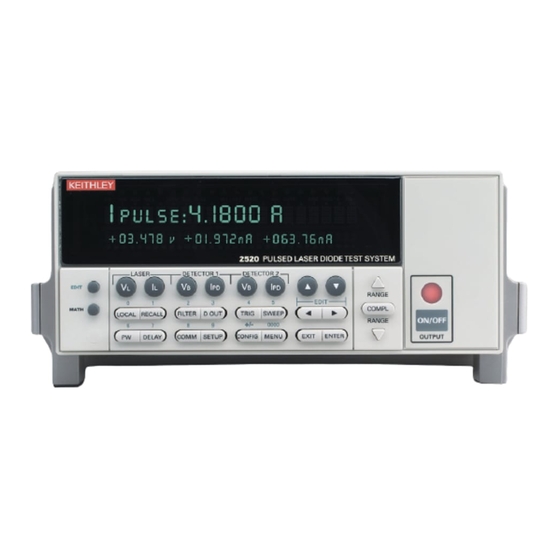
Quick Reference Guide Display format The Model 2520 display is used primarily to display measured readings and source values. The top line displays source values, and the bottom line shows measured values. Display example The following example shows the unit displaying the laser diode source value on the top... -
Page 17: Basic Connections
Quick Reference Guide Basic connections WARNING While the Model 2520 does not incorporate a laser, it is designed to operate (power) laser diode devices. Read all safety precautions listed at the beginning of this manual. The following safety practices must be used to... -
Page 18: Testhead Connections
Turn off the mainframe power before connecting or disconnecting the testhead to the mainframe. Figure 5 shows connections between the Model 2520 mainframe and the testhead. Using the supplied cables, make connections as follows: • Connect the mainframe TESTHEAD CONN 1 connector to the testhead MAINFRAME CONN 1 connector. -
Page 19: Interlock Connections
Quick Reference Guide Interlock connections The Model 2520 has two interlock circuits, a remote interlock and a key interlock. NOTE Both interlocks must be enabled to operate; otherwise the source outputs will not turn on. A remote interlock switch should be wired to pins 1 and 9 of the REMOTE INTERLOCK... -
Page 20: Typical Test Connections
Twist the SENSE cables together to further reduce magnetic coupling. • Connect the VOLTAGE SENSE leads as close to the body of the DUT as possible. See the specifications in Appendix A and information in Appendix F of the Model 2520 User’s Manual for more information. -
Page 21: Polarity
Press CONFIG > LASER I , LASER V , or DETECTOR I > select POLARITY. See Section 3 of the Model 2520 User’s Manual for details on polarity. Remote command programming Table 1 lists the SCPI commands to select polarity. -
Page 22: Basic Operation
The :READ? command is typically used to trigger the unit and request the data string. The data string is sent to the computer when the Model 2520 is addressed to talk. The data string is typically made up of three elements separated by commas. The first element is the voltage reading, the second is the detector #1 current reading, and the third is the detector #2 current reading. -
Page 23: Table 3 Scpi Commands For Basic Laser Diode Tests
Set detector #1 source voltage (0 to ±20). :SOURce3:VOLTage <voltage> Set detector #2 source voltage (0 to ±20). 5A maximum pulse mode only. 1A maximum in DC mode. Minimum and default pulse delay and width values depend on pulse duty cycle. See Model 2520 specifications. -
Page 24: Table 4 Basic Laser Diode Test Programming Example
Quick Reference Guide Programming example Table 4 shows a typical command sequence for basic laser diode testing. This program- ming example sets up the current and voltage sources, the measurement functions, and triggers and acquires one set of voltage and current readings. Table 4 Basic laser diode test programming example Step... -
Page 25: Settings To Optimize Performance
Quick Reference Guide Settings to optimize performance Range To achieve best accuracy, the Model 2520 should be on the lowest possible measurement range. Use the RANGE keys to select the range after pressing the appropriate measurement function key (V or I ). -
Page 26: Table 5 Filter Commands
Quick Reference Guide Remote filter programming Table 5 summarizes filter commands. Table 5 Filter commands Commands Description [:SENSe[1]]:AVERage:COUNt <count> Set average filter count (1 to 100). [:SENSe[1]]:AVERage[:STATe] <state> Enable/disable average filter (ON or OFF). :SENSe2:AVERage:COUNt <count> Set average filter count (1 to 100). :SENSe2:AVERage[:STATe] <state>... -
Page 27: Features To Enhance Dut Testing
Quick Reference Guide Features to enhance DUT testing Sweep operation Sweep types The three available sweep types are linear staircase, logarithmic staircase, and custom (list). Both types of staircase sweeps can be performed from the front panel, but custom sweeps are available only via remote. Linear staircase sweep When the sweep shown in Figure 8... -
Page 28: Logarithmic Staircase Sweep (Example)
Quick Reference Guide Logarithmic staircase sweep This sweep is similar to the linear staircase sweep. The steps, however, are done on a logarithmic scale. The symmetrical log points for the steps are determined by the specified number of sweep points. Figure 9 shows a 5-point log sweep from 1 to 10mA. -
Page 29: Custom Pulse Sweep (Example)
Quick Reference Guide Custom sweep This sweep type lets you configure a customized sweep (via remote only). Programmable sweep list parameters include the number of measurement points in the sweep, the current source level at each point, pulse width, and pulse delay. Figure 10 shows an example of a custom sweep. -
Page 30: Performing Sweeps
Quick Reference Guide Performing sweeps Performing a linear staircase sweep Perform the following steps to run a linear staircase sweep: Configure the laser diode and detector source and measure functions. Configure the linear staircase sweep, including start, stop, and step values, as previously explained. -
Page 31: Commands For Linear And Log Staircase Sweeps
5A maximum pulse mode only. 1A maximum in DC mode. Minimum and default pulse delay and width values depend on pulse duty cycle. See Model 2520 specifications. If delay and width are not programmed, default values of 1.5ms (delay) and 500ns (width) will be used, but queries will return 0. -
Page 32: Linear Staircase Sweep Programming Example
Quick Reference Guide Programming examples The command sequence for a linear staircase sweep is provided in Table 9, while Table 10 lists commands for a custom sweep. Table 9 Linear staircase sweep programming example Command Description *RST Restore GPIB default conditions. :FORM:ELEMVOLT1,CURR2,CURR3 Laser diode voltage, detector current data. -
Page 33: Math Functions
Quick Reference Guide Math functions The Model 2520 has built-in math functions to calculate conductance, resistance, MX + B, power, and delta. Conductance, resistance, and power are available only for laser diode voltage measurements. MX + B is available for all three measurement functions (laser diode voltage and both detector current measurements). - Page 34 Quick Reference Guide MX + B This math function multiplies the measured laser diode voltage or photodiode detector current by an offset factor and adds an offset value as follows: Reading = MX + B where: M = gain (slope) factor X = measured laser diode voltage (V ) or photodiode current (I B = offset value...
-
Page 35: Math Function Commands
Quick Reference Guide Remote math functions Table 11 summarizes commands to control the measurement math functions by remote, while Table 12 shows a programming example. Table 11 Math function commands Command Description :CALCulate[1]:DATA? Request laser diode math reading. :CALCulate[1]:FORMat <function> Set laser diode math function (MXB[1], CONDuctance[1], POWER[1], or RESistance[1]). -
Page 36: Math Function Programming Example
Quick Reference Guide Table 12 Math function programming example Command Description :CALC1:FORMPOWER1 Select laser diode power function. ;CALC1:KMAT:MUN ‘W’ Set “W” math units. :CALC1:STAT ON Enable laser diode math. :CALC2:KMAT:MBF 5e-3 Detector #1 MX + B offset (B) = 5e-3. :CALC2:KMAT:MMF 0.5 Detector #1 slope (M) =0.5. - Page 37 Specifications are subject to change without notice. All Keithley trademarks and trade names are the property of Keithley Instruments, Inc. All other trademarks and trade names are the property of their respective companies. Keithley Instruments, Inc. 28775 Aurora Road • Cleveland, Ohio 44139 • 440-248-0400 • Fax: 440-248-6168 1-888-KEITHLEY (534-8453) •...
Need help?
Do you have a question about the 2520 and is the answer not in the manual?
Questions and answers