
Related Manuals for Keithley 2520


Summary of Contents for Keithley 2520
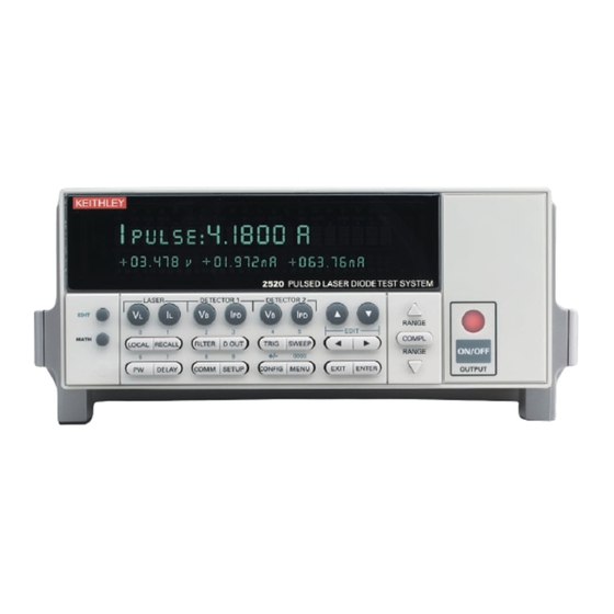
- Page 1 Model 2520 Pulsed Laser Diode Test System Service Manual 2520-902-01 Rev. B / January 2006 G R E A T E R M E A S U R E C O N F I D E N C E...
- Page 2 WARRANTY Keithley Instruments, Inc. warrants this product to be free from defects in material and workmanship for a period of 1 year from date of shipment. Keithley Instruments, Inc. warrants the following items for 90 days from the date of shipment: probes, cables, rechargeable batteries, diskettes, and documentation.
- Page 3 Model 2520 Pulsed Laser Diode Test System Service Manual ©2001, Keithley Instruments, Inc. All rights reserved. Cleveland, Ohio, U.S.A. Second Printing, January 2006 Document Number: 2520-902-01 Rev. B...
- Page 4 Revision A (Document Number 2520-902-01) ............September 2001 Revision B (Document Number 2520-902-01) ............January 2006 All Keithley product names are trademarks or registered trademarks of Keithley Instruments, Inc. Other brand names are trademarks or registered trademarks of their respective holders.
- Page 5 Keithley products are designed for use with electrical signals that are rated Measurement Category I and Measurement Category II, as described in the International Electrotechnical Commission (IEC) Standard IEC 60664. Most measurement, control, and data I/O signals are Measurement Category I and must not be directly connected to mains voltage or to voltage sources with high transient over-voltages.
- Page 6 To maintain protection from electric shock and fire, replacement components in mains circuits, including the power transformer, test leads, and input jacks, must be purchased from Keithley Instruments. Standard fuses, with applicable national safety ap- provals, may be used if the rating and type are the same. Other components that are not safety related may be purchased from other suppliers as long as they are equivalent to the original component.
-
Page 7: Table Of Contents
Table of Contents Performance Verification Introduction ................Verification test requirements ............ Environmental conditions ........... Warm-up period ..............Line power ................Recommended test equipment ........... Resistor characterization ............. Verification limits ..............Example limits calculation ..........Restoring factory defaults ............Performing the verification test procedures ....... Test summary .............. - Page 8 Calibration errors ................ Front panel error reporting ..........Remote error reporting ............Aborting calibration steps ............Testhead connections ..............2-10 Front panel calibration .............. 2-10 Remote calibration ..............2-22 Remote calibration command summary ......2-22 Remote calibration procedure ........... 2-23 Routine Maintenance Introduction ................
- Page 9 Motherboard removal ..............Front panel disassembly ............. Removing power components ............ Power supply module removal ........... Power module removal ............Instrument re-assembly .............. Testhead disassembly ..............Case disassembly ..............Output board removal ............Input board removal ............Testhead re-assembly ..............Replaceable Parts Introduction ................
- Page 11 Detector 2 current measurement calibration connections ......... 2-19 Figure 2-9 Compliance calibration connections ..............2-20 Routine Maintenance Figure 3-1 Model 2520 rear panel ..................Troubleshooting Figure 4-1 Overall block diagram ..................Figure 4-2 Analog circuitry block diagram ................Figure 4-3 Power supply block diagram ................
- Page 12 List of Tables Performance Verification Table 1-1 Recommended verification equipment ............... Table 1-2 Voltage measurement accuracy limits ..............Table 1-3 Current source verification limits ..............1-12 Table 1-4 Current measurement verification limits ............1-14 Calibration Table 2-1 Recommended calibration equipment ..............Table 2-2 Calibration menu ....................
-
Page 13: Performance Verification
Performance Verification... -
Page 14: Introduction
Model 2520 Pulsed Laser Diode Test System Service Manual Introduction Use the procedures in this section to verify that Model 2520 Pulsed Laser Diode Test System accuracy is within the limits stated in the instrument’s one-year accuracy specifications. You can perform these verification procedures: •... - Page 15 Model 2520 Pulsed Laser Diode Test System Service Manual Performance Verification WARNING While the Model 2520 does not incorporate a laser, it is designed to operate (power) laser diode devices. Read all safety precautions listed at the beginning of the Model 2520 User’s Manual. The following...
-
Page 16: Verification Test Requirements
Also, allow the test equipment to warm up for the minimum time specified by the manufacturer. Line power The Model 2520 requires a line voltage of 100V to 240V and a line frequency of 50 or 60 Hz. Verification tests must be performed within this range. -
Page 17: Recommended Test Equipment
Table 1-1. Keep in mind, however, that test equipment uncertainty will add to the uncertainty of each measurement. Generally, test equipment uncertainty should be at least four times better than corresponding Model 2520 specifications. Table 1-1 Recommended verification equipment Description... -
Page 18: Verification Limits
Laser diode voltage measurement accuracy • Laser diode current source accuracy • Detector voltage bias source accuracy If the Model 2520 is not within specifications and not under warranty, see the calibration procedures in Section 2, Calibration, for information on calibrating the unit. -
Page 19: Test Considerations
±10V DC. Exceeding this value may cause a shock hazard. Testhead connections The Model 2520 mainframe must be connected to the testhead in order to perform the verification procedures. Using Figure 1-1 as a guide, make testhead connections as... - Page 20 Performance Verification Model 2520 Pulsed Laser Diode Test System Service Manual Figure 1-1 Testhead connections Model 2520 Testhead Model 2520 Mainframe WARNING: NO INTERNAL OPERATOR SERVICABLE PARTS, SERVICE BY QUALIFIED PERSONNEL ONLY. DISABLED (PULL TO REMOVE) BOTH INTERLOCKS MUST BE ENABLED TO OPERATE...
-
Page 21: Voltage Measurement Accuracy
With the power off, connect the voltage calibrator to the testhead VOLTAGE SENSE jacks, as shown in Figure 1-2. Turn on the Model 2520 and calibrator, and allow them to warm up for a minimum of one hour. Restore BENCH defaults as covered previously in “Restoring factory defaults” on page 1-6. -
Page 22: Current Source Accuracy
Figure 1-4 Figure 1-5 for mounting and connections of parallel resistors. Turn on the Model 2520 and DMM, and allow them to warm up for a minimum of one hour. Restore front panel (BENCH) defaults as outlined previously in “Restoring factory defaults”... - Page 23 Model 2520 Pulsed Laser Diode Test System Service Manual Performance Verification 1-11 Figure 1-3 Connections for current source verification tests 10W Cable (SC-182) Input HI 20cm Tie Shields Input LO Model 2001 DMM Model 2520 Testhead Together SENSE INPUT W 4 WIRE...
- Page 24 1-12 Performance Verification Model 2520 Pulsed Laser Diode Test System Service Manual Figure 1-5 Resistor mounting and connections Resistor Edge View 0.5in Maximum Loop Resistors Area Board Calculate the current using the voltage value and characterized resistance value: I = V/R. Recalculate reading limits from these values, then verify that the current is within those limits.
- Page 25 Model 2520 Pulsed Laser Diode Test System Service Manual Performance Verification 1-13 Figure 1-6 Connections for current source pulse verification tests 10W Cable (SC-182) 20cm Tie Shields Model 2520 Testhead Together 10 to 15W Resistor (500mA Range, 20 RN60 Type 300W in Parallel)
-
Page 26: Current Measurement Accuracy
1-7. (See Figure 1-4 Figure 1-5 parallel resistor construction.) Turn on the Model 2520 and DMM, and allow them to warm up for a minimum of one hour. Select the DMM DC volts function, and enable auto-range. Figure 1-7 Connections for DETECTOR 1 current measurement verification tests... - Page 27 Model 2520 Pulsed Laser Diode Test System Service Manual Performance Verification 1-15 After verifying all ranges for DETECTOR 1, repeat the entire procedure for DETECTOR 2. (Connect the calibrator to the TESTHEAD DETECTOR 2 jack, and select that channel by pressing DETECTOR 2 I .
-
Page 28: Voltage Bias Source Accuracy
With the power off, connect the digital multimeter to the Model 2520 testhead DETECTOR 1 jack, as shown in Figure 1-9. Turn on the Model 2520 and DMM, and allow them to warm up for a minimum of one hour. Restore BENCH defaults as covered previously in “Restoring factory defaults” on page 1-6. - Page 29 Model 2520 Pulsed Laser Diode Test System Service Manual Performance Verification 1-17 Figure 1-10 Connections for DETECTOR 2 voltage bias source verification tests Input HI Model 2520 Testhead Model 2001 DMM Center Conductor SENSE INPUT Ω 4 WIRE 350V 1100V...
-
Page 31: Calibration
Calibration... -
Page 32: Introduction
Model 2520 Pulsed Laser Diode Test System Service Manual Introduction Use the procedures in this section to calibrate the Model 2520 Pulsed Laser Diode Test System. These procedures require accurate test equipment to supply and measure precise DC currents and voltages. Calibration can be performed either from the front panel or by sending SCPI calibration commands over the IEEE-488 bus or RS-232 port with the aid of a computer. - Page 33 Model 2520 Pulsed Laser Diode Test System Service Manual Calibration WARNING While the Model 2520 does not incorporate a laser, it is designed to operate (power) laser diode devices. Read all safety precautions listed at the beginning of the Model 2520 User’s Manual. The following...
-
Page 34: Environmental Conditions
Also, allow the test equipment to warm up for the minimum time specified by the manufacturer. Line power The Model 2520 requires a line voltage of 100V to 240V at line frequency of 50 or 60Hz. The instrument must be calibrated while operating from a line voltage within this range. Calibration considerations When performing the calibration procedures: •... -
Page 35: Calibration Cycle
For optimum calibration accuracy, test equipment specifications should be at least four times better than corresponding Model 2520 specifications. Table 2-1 Recommended calibration equipment... -
Page 36: Calibration Menus
Calibration Model 2520 Pulsed Laser Diode Test System Service Manual Calibration menus Table 2-2 summarizes the main calibration menu selections. To enter the calibration menu, press the MENU key, select CAL, then press ENTER. Use the EDIT keys to move the cursor and scroll through menu selections. -
Page 37: Unlocking Calibration
Model 2520 Pulsed Laser Diode Test System Service Manual Calibration Unlocking calibration Before performing calibration, you must first unlock calibration by entering or sending the calibration password as explained in the following paragraphs. Unlocking calibration from the front panel Press the MENU key, then choose CAL, and press ENTER. The instrument will... -
Page 38: Changing The Password
Calibration Model 2520 Pulsed Laser Diode Test System Service Manual Changing the password The default password (002520) may be changed from the front panel or via remote, as discussed below. Changing the password from the front panel Follow the steps below to change the password from the front panel: Press the MENU key, choose CAL, and press ENTER. -
Page 39: Viewing Calibration Dates And Calibration Count
(bit 2) in the status byte. (Use the *STB? query to request the status byte.) Query the instrument for the type of error by using the :SYST:ERR? query. The Model 2520 will respond with the error number and a text message describing the nature of the error. See Appendix B for details. -
Page 40: Testhead Connections
2-10 Calibration Model 2520 Pulsed Laser Diode Test System Service Manual Testhead connections The Model 2520 mainframe must be connected to the testhead in order to perform calibration. Using Figure 2-1 as a guide, make testhead connections as follows: CAUTION Make sure power is turned off before making connections. - Page 41 2-11 Step 1: Prepare the Model 2520 for calibration Turn on the Model 2520 and the calibration equipment, and allow them to warm up for a minimum of one hour before performing calibration. Press the MENU key, choose CAL, and press ENTER. Select UNLOCK, and then press ENTER.
- Page 42 2-12 Calibration Model 2520 Pulsed Laser Diode Test System Service Manual Connect the calibrator to the Model 2520 testhead VOLTAGE SENSE jacks, as shown in Figure 2-2. (Connect calibrator HI to VOLTAGE SENSE LO; connect calibrator LO to VOLTAGE SENSE HI.) Turn on the calibrator output, set the calibrator voltage to -10.000V, then press...
- Page 43 IL-CAL Connect Calibration Resistor to Pulse Sense and Pulse Source Connect the 10 to 15Ω resistor to the Model 2520 testhead VOLTAGE SENSE and CURRENT OUTPUT jacks, as shown in Figure 2-3. Press ENTER to complete calibration of the present range.
- Page 44 Follow the steps below to calibrate current source pulse low. Table 2-6 summarizes calibration currents and test resistance values. Connect DMM and 100Ω resistor to the Model 2520 testhead CURRENT OUTPUT jacks, as shown in Figure 2-4. Select the DMM DC volts function, and enable auto-range.
- Page 45 Model 2520 Pulsed Laser Diode Test System Service Manual Calibration 2-15 Adjust the display to agree with the calculated, then press ENTER. The unit displays the following: Pulse Low CAL Press ENTER to Output +15.000mA Press ENTER. The unit displays: DMM RDG: +15.000mA...
- Page 46 DMM RDG: -20.00000 V Use , , , , ENTER or EXIT. Note the DMM voltage reading, then use the EDIT keys to adjust the Model 2520 display value to agree with that reading. Figure 2-5 Detector 1 voltage bias source calibration connections...
- Page 47 Use , , , , ENTER or EXIT. Note the DMM voltage reading, then use the EDIT keys to adjust the Model 2520 display value to agree with the reading. Press ENTER. The unit will display the prompt for the +20V calibration point: Vbias 1 CAL Press ENTER to Output +20.000 V...
- Page 48 Select the DMM DC volts function, and enable auto-range. Temporarily short the ends of the DMM test leads together, then enable REL to null offsets. Connect the 2kΩ resistor and the DMM to the Model 2520 testhead DETECTOR 1 jack, as shown in Figure 2-7.
- Page 49 DMM RDG: -20.000 V Use , , , , ENTER or EXIT. Use the EDIT keys to adjust the Model 2520 display value to agree with the DMM voltage reading. Press ENTER. The instrument will prompt for 0V calibration: Ipd 1 CAL Press ENTER to Output +00.000 V...
- Page 50 Press ENTER. The instrument will display: DMM RDG: +10.500 V Use , , , , ENTER or EXIT. Note the DMM reading, then adjust the Model 2520 display to agree with that value. Press ENTER. The instrument will display: DMM RDG: +03.000 V Use , , , , ENTER or EXIT.
- Page 51 Model 2520 Pulsed Laser Diode Test System Service Manual Calibration 2-21 Step 8: Enter calibration dates and save calibration NOTE For temporary calibration without saving new calibration constants, proceed to Step 9: Lock out calibration. From the CALIBRATION menu, select SAVE, and then press ENTER. The unit...
-
Page 52: Remote Calibration
2-22 Calibration Model 2520 Pulsed Laser Diode Test System Service Manual Remote calibration Use the following procedure to perform remote calibration by sending SCPI commands over the IEEE-488 bus or RS-232 port. The remote commands and appropriate parameters are separately summarized for each step. -
Page 53: Remote Calibration Procedure
With the power off, connect the Model 2520 to the controller IEEE-488 interface or RS-232 port using a shielded interface cable. Turn on the Model 2520 and the test equipment, and allow them to warm up for a minimum of one hour before performing calibration. - Page 54 :SENS1:VOLT:POL NEG :CAL:PROT:SENS1 0 :SENS1:VOLT:POL POS :CAL:PROT:SENS1 0 :DIAG:KEIT:FCON:LO OFF Connect the calibrator to the Model 2520 testhead VOLTAGE SENSE jacks, as shown in Figure 2-2. Set the calibrator voltage output to -10.000V, and turn on its output. Send the following command to calibrate the +10V point: :CAL:PROT:SENS1 10 Reverse the calibrator HI and LO connections.
-
Page 55: Table 2-9 Voltage Measurement Calibration Voltages And Commands
Model 2520 Pulsed Laser Diode Test System Service Manual Calibration 2-25 Table 2-9 Voltage measurement calibration voltages and commands Voltage range Calibration voltages* Calibration commands :SOURI:FUNC:SHAP DC :SENS1:VOLT:RANG 5 :DIAG:KEIT:FCON:HI ON :DIAG:KEIT:FCON:LO ON :SENS1:VOLT:POL NEG :CAL:PROT:SENS1 0 :SENS1:VOLT:POL POS :CAL:PROT:SENS1 0 :DIAG:KEIT:FCON:LO OFF -5.00000V... - Page 56 Send the following query to request the Model 2520 voltage measurement: :SENS1:DATA? Note the voltage reading returned by the Model 2520 in step 10, then calculate the actual sourced current as follows: I = V/R. Here, I is the actual sourced current, V is the returned Model 2520 voltage reading, and R is the actual resistance value.
-
Page 57: Table 2-10 Remote Current Source Calibration Summary
Model 2520 Pulsed Laser Diode Test System Service Manual Calibration 2-27 Table 2-10 Remote current source calibration summary Current range Calibration resistance Calibration commands :SOUR1:FUNC:SHAP PULS :SENS1:VOLT:POL POS :SOUR1:CURR:POL POS 500mA 10 to 15Ω :SOUR1:PULS:TRAN:STAT ON | OFF :SENS1:VOLT:RANG 10 :SOUR1:CURR:RANG 0.5... - Page 58 Follow these steps to calibrate current source pulse low. Table 2-11 summarizes calibration resistances and commands. Connect the 100Ω resistor and DMM to the Model 2520 testhead CURRENT OUTPUT jacks, as shown in Figure 2-4. Select the DMM DC volts function, and enable auto-range.
-
Page 59: Table 2-11 Remote Pulse Low Calibration Summary
Model 2520 Pulsed Laser Diode Test System Service Manual Calibration 2-29 Enable slow pulses: :SOUR1:PULS:TRAN:STAT ON Repeat steps 5 through 12. Send this command to turn off the output: :OUTP1 OFF Disconnect the 100Ω resistor, then connect the 10Ω resistor in its place. - Page 60 Follow these steps to calibrate the two voltage bias sources. Table 2-12 summarizes calibration voltages and commands. Connect the DMM to the Model 2520 testhead DETECTOR 1 and VOLTAGE SENSE HI jacks, as shown in Figure 2-5. Select the DMM DC voltage function, and enable auto-range.
-
Page 61: Table 2-12 Remote Voltage Bias Source Calibration Summary
Select the DMM DC voltage function, and enable auto-range. Temporarily short the ends of the DMM test leads together, and enable the REL mode to null offsets. Connect the DMM and 2kΩ resistor to the Model 2520 testhead DETECTOR 1 jack, as shown in Figure 2-7. - Page 62 2-32 Calibration Model 2520 Pulsed Laser Diode Test System Service Manual Send this command to turn on the outputs: :OUTP1 ON Send the following command to output -20V: :SOUR2:VOLT -20 Note the DMM voltage reading, then calculate the current from the characterized...
-
Page 63: Table 2-13 Remote Current Measurement Calibration Currents And Commands
Model 2520 Pulsed Laser Diode Test System Service Manual Calibration 2-33 Table 2-13 Remote current measurement calibration currents and commands Calibration Channel Current range Test resistor* currents* Calibration commands* Detector 1 10mA 2kΩ :OUTP1 ON :SENS2:CURR:RANG 10e-3 :SOUR1:FUNC:SHAP DC :SENSE2:CURR:POL POS... - Page 64 2-34 Calibration Model 2520 Pulsed Laser Diode Test System Service Manual Table 2-13 (continued) Remote current measurement calibration currents and commands Calibration Channel Current range Test resistor* currents* Calibration commands* Detector 1 100mA 200Ω :SENS2:CURR:RANG 100e-3 :SOUR1:FUNC:SHAP DC :SENSE2:CURR:POL POS...
- Page 65 Model 2520 Pulsed Laser Diode Test System Service Manual Calibration 2-35 Table 2-13 (continued) Remote current measurement calibration currents and commands Calibration Channel Current range Test resistor* currents* Calibration commands* Detector 2 50mA 400Ω :SENS3:CURR:RANG 50e-3 :SOUR1:FUNC:SHAP DC :SENSE3:CURR:POL POS...
- Page 66 Step 7: Compliance calibration Follow the steps below to calibrate compliance. Table 2-14 summarizes calibration steps. Connect the DMM to the Model 2520 testhead CURRENT OUTPUT jacks, as shown in Figure 2-9. Select the DMM DC volts function, and enable auto-range.
- Page 67 Model 2520 Pulsed Laser Diode Test System Service Manual Calibration 2-37 Step 8: Program calibration dates Use the following commands to set the calibration date and calibration due date: :CAL:PROT:DATE <yyyy>, <mm>, <dd> (Calibration date) :CAL:PROT:NDUE <yyyy>, <mm>, <dd> (Next calibration due date) Note that the year, month, and date must be separated by commas.
- Page 68 2-38 Calibration Model 2520 Pulsed Laser Diode Test System Service Manual...
-
Page 69: Routine Maintenance
Routine Maintenance... -
Page 70: Introduction
Routine Maintenance Model 2520 Pulsed Laser Diode Test System Service Manual Introduction The information in this section deals with routine type maintenance that can be performed by the operator and includes information on line fuse replacement. Line fuse replacement WARNING Disconnect the line cord at the rear panel, and remove all test leads connected to the instrument before replacing the line fuse. -
Page 71: Table 3-1 Power Line Fuse
Model 2520 Pulsed Laser Diode Test System Service Manual Routine Maintenance Perform the following steps to replace the line fuse: Using a small flat-blade screwdriver, carefully release the locking tab that secures the fuse carrier to the power module. Pull out the fuse carrier, and replace the fuse with the type specified in Table 3-1. - Page 72 Routine Maintenance Model 2520 Pulsed Laser Diode Test System Service Manual...
-
Page 73: Troubleshooting
Troubleshooting... -
Page 74: Introduction
Model 2520 Pulsed Laser Diode Test System Service Manual Introduction This section of the manual will assist you in troubleshooting and repairing the Model 2520 Pulsed Laser Diode Test System. Included are self-tests, test procedures, troubleshooting tables, and circuit descriptions. Note that disassembly instructions are located in... -
Page 75: Power-On Self-Test
Model 2520 Pulsed Laser Diode Test System Service Manual Troubleshooting Power-on self-test During the power-on sequence, the Model 2520 will perform a checksum test on its EPROM and test its RAM. If one of these tests fails, the instrument will lock up. Front panel tests There are three front panel tests: one to test the functionality of the front panel keys and two to test the display. -
Page 76: Char Set Test
Troubleshooting Model 2520 Pulsed Laser Diode Test System Service Manual Select DISPLAY-PATTERNS, and press ENTER to start the display test. There are five parts to the display test. Each time a front panel key (except EXIT) is pressed, the next part of the test sequence is selected. The five parts of the test sequence are as follows: •... -
Page 77: Overall Block Diagram
Model 2520 Pulsed Laser Diode Test System Service Manual Troubleshooting Overall block diagram Figure 4-1 shows an overall block diagram of the Model 2520. Circuitry may be divided into two general areas: • Analog circuits — includes measurement circuits for voltage, and I-V converter for current, A/D converters, and voltage bias and current source circuits. - Page 78 Troubleshooting Model 2520 Pulsed Laser Diode Test System Service Manual Figure 4-1 Overall block diagram GPIB Front Panel Keypad RS-232 MC68332 Digital I/O 2 Line VFD Microprocessor Trigger Link Detector 1 Voltage Source Detector 1 ±20V, 100mA Max SRAM 10MHz...
-
Page 79: Analog Circuits
Model 2520 Pulsed Laser Diode Test System Service Manual Troubleshooting Analog circuits Figure 4-2 shows a simplified block diagram of the analog circuits. Measurement circuits Voltage measurement circuits The laser diode voltage measurement circuits consist of U12, U13, and associated cir- cuitry. - Page 80 Troubleshooting Model 2520 Pulsed Laser Diode Test System Service Manual Figure 4-2 Analog circuitry block diagram Voltage Clamp U4, U6 U16,Q9 Laser Diode Current Source High Pulse Output Current High/Low Stage Amplifiers Control Data PULSED OUT Switch From MPU Terminals...
- Page 81 Source circuits Voltage bias source circuits Each Model 2520 voltage bias source is a digitally controlled source that can source up to ±20V @ 100mA. Digital control information from the MPU is converted by a DAC into an equivalent analog signal. U1 converts the detector 1 source data, while U2 converts detector 2 source data.
-
Page 82: Power Supply
Model 2520 Pulsed Laser Diode Test System Service Manual Power supply Figure 4-3 shows a block diagram of the Model 2520 power supply system. The supply has two separate power transformers, T1 and T2, as well as both regulated and unregu- lated supply voltages. -
Page 83: Digital Circuitry
Model 2520 Pulsed Laser Diode Test System Service Manual Troubleshooting 4-11 Digital circuitry Refer to Figure 4-4 for the following discussion on digital circuitry. Microcontroller The core digital circuitry uses a Motorola 68332 microcontroller (U15) running at 16.78MHz. The memory configuration includes a flash EEPROM (U3 and U4) and a RAM U2 and U17). - Page 84 4-12 Troubleshooting Model 2520 Pulsed Laser Diode Test System Service Manual Figure 4-4 Digital circuitry block diagram U3, U4 U2, U17 Serial RS-232 Interface Interface Reset E PROM GPIB Microprocessor IEEE-488 Interface U5, U6 To Display Board Controller 16.78MHz Data From A/D...
-
Page 85: Troubleshooting
Model 2520 Pulsed Laser Diode Test System Service Manual Troubleshooting 4-13 Troubleshooting Troubleshooting information for the various circuits is summarized below. Refer to the component layout drawings at the end of Section 6 for component locations. Display board checks If the front panel display tests indicate that there is a problem on the display board, use Table 4-1. -
Page 86: Power Supply Checks
4-14 Troubleshooting Model 2520 Pulsed Laser Diode Test System Service Manual Power supply checks Power supply problems can be checked out using Table 4-2. See “Principles of operation” on page 4-4 for circuit theory on the power supply. Table 4-2... -
Page 87: Digital Circuitry Checks
Model 2520 Pulsed Laser Diode Test System Service Manual Troubleshooting 4-15 Digital circuitry checks Digital circuit problems can be checked out using Table 4-3. See “Principles of operation” on page 4-4 for a digital circuit description. Table 4-3 Digital circuitry checks... -
Page 88: Analog Circuitry Checks
4-16 Troubleshooting Model 2520 Pulsed Laser Diode Test System Service Manual Analog circuitry checks Table 4-4 summarizes analog circuitry checks. Table 4-4 Analog circuitry checks Step Item/component Required condition Remarks DETECTOR 1 jack Apply +20mA Select detector 1 20mA range. -
Page 89: No Comm Link Error
Model 2520 Pulsed Laser Diode Test System Service Manual Troubleshooting 4-17 No comm link error A “No Comm Link” error indicates that the front panel display processor has stopped communicating with the main processor, which is located on the motherboard. This error indicates that the main processor ROMs (U3 and U4) may require re-seating in their sock- ets. - Page 90 4-18 Troubleshooting Model 2520 Pulsed Laser Diode Test System Service Manual...
-
Page 91: Disassembly
Disassembly... -
Page 92: Introduction
Model 2520 Pulsed Laser Diode Test System Service Manual Introduction This section explains how to handle, clean, and disassemble the Model 2520 Pulsed Laser Diode Test System. Disassembly drawings are located at the end of this section. Handling and cleaning To avoid contaminating PC board traces with body oil or other foreign matter, avoid touching the PC board traces while you are repairing the instrument. -
Page 93: Static Sensitive Devices
Use the assembly drawings located at the end of this section to assist you as you disassem- ble and re-assemble the Model 2520. Also, refer to these drawings for information about the Keithley part numbers of most mechanical parts in the unit. -
Page 94: Case Cover Removal
Disassembly Model 2520 Pulsed Laser Diode Test System Service Manual Case cover removal Follow the steps below to remove the case cover to gain access to internal parts. WARNING Before removing the case cover, disconnect the line cord and any test leads from the instrument. -
Page 95: Front Panel Disassembly
Model 2520 Pulsed Laser Diode Test System Service Manual Disassembly Unplug cables: • Unplug the ribbon cables from J1007 and J1033. • Unplug the cable going to the power supply module from J1011. • Unplug the cable going to the OUTPUT indicator from J1034. -
Page 96: Removing Power Components
Disassembly Model 2520 Pulsed Laser Diode Test System Service Manual Removing power components The following procedures to remove the power supply and/or power module require that the case cover and motherboard be removed, as previously explained. Power supply module removal... -
Page 97: Testhead Disassembly
Model 2520 Pulsed Laser Diode Test System Service Manual Disassembly Testhead disassembly Follow the procedures below in the following order to disassemble the testhead. Case disassembly Remove the eight screws that secure the case top to the case bottom. Remove the nuts and washers that secure the four BNC PULSED and two triax DETECTOR jacks to the front panel. - Page 98 Disassembly Model 2520 Pulsed Laser Diode Test System Service Manual...
-
Page 99: Replaceable Parts
Replaceable Parts... -
Page 100: Introduction
Model 2520 Pulsed Laser Diode Test System. Parts lists The electrical parts lists for the Model 2520 are shown in tables at the end of this section. For part numbers to the various mechanical parts and assemblies, use the Miscellaneous... - Page 101 Model 2520 Pulsed Laser Diode Test System Service Manual Replaceable Parts Table 6-1 Mainframe digital board parts list Circuit designation Description Keithley part no. CAP, .33UF, 20%, 50V, CERAMIC C-237-.33 C105,C106,C146,C147,C186,C187 CAP, 22P, 5%, 100V, CERAMIC C-465-22P C108 CAP, 1UF, 20%, 35V, TANTALUM...
- Page 102 Replaceable Parts Model 2520 Pulsed Laser Diode Test System Service Manual Table 6-1 (continued) Mainframe digital board parts list Circuit designation Description Keithley part no. C237 CAP, 1000P, 10%, 100V, CERAMIC C-451-1000P C239,C263,C287 CAP, 47P, 5%, 100V, CERAMIC C-465-47P C240-C245,C250,C253-C262, CAP, .1UF, 20%, 50V, CERAMIC...
- Page 103 Model 2520 Pulsed Laser Diode Test System Service Manual Replaceable Parts Table 6-1 (continued) Mainframe digital board parts list Circuit designation Description Keithley part no. CR7,CR12 ULTRA FAST BRIDGE RECTIFIER, RF-123 EDF1BM POLYSWITCH, SMD030-2 FU-103 FOR CS-501 4-40X5/16 PHILLIPS PAN HD...
- Page 104 Replaceable Parts Model 2520 Pulsed Laser Diode Test System Service Manual Table 6-1 (continued) Mainframe digital board parts list Circuit designation Description Keithley part no. R131 RES, 24.3, 1%, 100MW, THICK FILM R-418-24.3 R133,R136,R138,R163-R165,R175 RES, 1K, 1%, 100MW, THICK FILM...
- Page 105 Model 2520 Pulsed Laser Diode Test System Service Manual Replaceable Parts Table 6-1 (continued) Mainframe digital board parts list Circuit designation Description Keithley part no. RES, 20, 1%, 100MW, THICK FILM R-418-20 RES, 100, 5%, 250MW, METAL FILM R-376-100 R67,R87 RES, .0499, 1%, 100MW, THICK FILM...
- Page 106 Replaceable Parts Model 2520 Pulsed Laser Diode Test System Service Manual Table 6-1 (continued) Mainframe digital board parts list Circuit designation Description Keithley part no. U38,U49 32 BIT BUS SWITCH, HOTSWITCH LSI-260 PROGRAMMED ROM 2520-802B01 LARGE SCALE IC SMT LSI-244...
- Page 107 Model 2520 Pulsed Laser Diode Test System Service Manual Replaceable Parts Table 6-2 Mainframe display board parts list Circuit designation Description Keithley part no. C901 CAP, 22UF, 20%, 6.3, TANTALUM C-417-22 C902,C904,C907,C908,C910 CAP, .1UF, 20%,100V, CERAMIC C-436-.1 C903,C905,C906,C909,C911 CAP, .1UF, 20%, 50V, CERAMIC C-418-.1...
- Page 108 6-10 Replaceable Parts Model 2520 Pulsed Laser Diode Test System Service Manual Table 6-3 Test head board parts list Circuit designation Description Keithley part no. C1,C52,C53,C59,C60,C2 CAP, 470UF, 20%, 63V, ALUM ELEC C-477-470 C11,C13,C17,C18,C29,C30,C33, CAP, 22U, 20%, 25V, ALUM ELEC...
- Page 109 Model 2520 Pulsed Laser Diode Test System Service Manual Replaceable Parts 6-11 Table 6-3 (continued) Test head board parts list Circuit designation Description Keithley part no. CONN, .05 MINI-D RIBBION, 26 PINS CS-1118-1 CONN, HEADER, 36 PINS CS-368-36 CONN, HEADER, STRAIGHT SOLDER PIN CS-368-26...
- Page 110 6-12 Replaceable Parts Model 2520 Pulsed Laser Diode Test System Service Manual Table 6-3 (continued) Test head board parts list Circuit designation Description Keithley part no. R4,R6 RES, 8.98K, .1%, .125W, THIN FILM R-456-8.98K R40,R41,R70,R71 RES, 1.1K, .1%, .125W, THIN FILM R-456-1.1K...
- Page 111 Model 2520 Pulsed Laser Diode Test System Service Manual Replaceable Parts 6-13 Table 6-4 Pulse board parts list Circuit designation Description Keithley part no. CAP, .1UF, 10%, 25V, CERAMIC C-495-.1 C10,C11,C12,C13 CAP, 680U, 20%, 50V, ALUM ELEC C-578-680 CAP, 10U, 20%, 35V, TANTALUM...
- Page 112 6-14 Replaceable Parts Model 2520 Pulsed Laser Diode Test System Service Manual Table 6-4 (continued) Pulse board parts list Circuit designation Description Keithley part no. Q5,Q6,Q7,Q8,Q17,Q20,Q23 TRANS, PNP, MMBT3906L TG-244 TRANS, HEXFET POWER MOSFET TG-304 RES, 2.5, .1%, 1.5W, METAL FOIL R-501-2.5...
- Page 113 Model 2520 Pulsed Laser Diode Test System Service Manual Replaceable Parts 6-15 Table 6-4 (continued) Pulse board parts list Circuit designation Description Keithley part no. RES, 332, 1%, 100MW, THICK FILM R-418-332 RES, 249, 1%, .1W, THIN FILM R-438-249 R77-R81...
- Page 114 6-16 Replaceable Parts Model 2520 Pulsed Laser Diode Test System Service Manual Table 6-5 Miscellaneous parts list Description Keithley part no. AC ON/OFF LINE SWITCH PM-6-1 BEZEL, REAR 428-303D CABLE ASSEMBLY, BNC CA-290-1B CHASSIS 2520-301B CHASSIS ASSEMBLY 2520-302B CONDUCTIVE RUBBER SWITCH...
- Page 115 Model 2520 Pulsed Laser Diode Test System Service Manual Replaceable Parts 6-17 Table 6-5 (continued) Miscellaneous parts list Description Keithley part no. REAR PANEL 2520-303A SAFETY COVER, MODIFIED 2520-330A SWITCH SW-513A SWITCH SW-513A TRIAX CABLE CA-289-1A...
- Page 116 6-18 Replaceable Parts Model 2520 Pulsed Laser Diode Test System Service Manual...
-
Page 117: Specifications
Specifications... - Page 118 Specifications Model 2520 Pulsed Laser Diode Test System Service Manual 2520 Pulsed Laser Diode Test System LASER DIODE PULSE OR DC CURRENT SOURCE SPECIFICATIONS DRIVE CURRENT OFF CURRENT APPROX. RMS NOISE APPROX. SOURCE PROGRAMMING ELECTRICAL ACURACY (typical) PROGRAMMING ELECTRICAL ACURACY...
- Page 119 Pulse Waveform Flatness - 5A into 2 ohms Output: 500mA DC on 500mA range and 1A DC on 5A range. 5.06 Full Pulse Refer to 2520 Service Manual for test setup of current accuracy. 5.04 Figures 1 and 2 are typical pulse outputs into resistive loads. 5.02...
-
Page 120: Accuracy Calculations
Specifications Model 2520 Pulsed Laser Diode Test System Service Manual Accuracy calculations The information below discusses how to calculate accuracy for both measurement and source specifications. Measurement accuracy Measurement accuracy specifications are stated as follows: Accuracy = ±(% of reading + offset) As an example of how to calculate the actual limits, assume an input current of 10mA on the 20mA range. -
Page 121: Calibration Reference
Calibration Reference... -
Page 122: Introduction
Calibration Reference Model 2520 Pulsed Laser Diode Test System Service Manual Introduction This appendix contains detailed information on the various Model 2520 remote calibration commands, calibration error messages, and methods to detect the end of each calibration step. Section 2 of this manual covers detailed calibration procedures. -
Page 123: Miscellaneous Commands
Example Send default code of KI002520. :CAL:PROT:CODE 'KI002520' :COUNT? (:CALibration:PROTected:COUNT?) Purpose To request the number of times the Model 2520 has been calibrated. Format :cal:prot:count? Response Number of times calibrated. Description The :COUNT? query may be used to determine the total number of times the Model 2520 has been calibrated. - Page 124 Calibration Reference Model 2520 Pulsed Laser Diode Test System Service Manual :LOCK (:CALibration:PROTected:LOCK) Purpose To lock out calibration. Format :cal:prot:lock Query :cal:prot:lock? Response Calibration unlocked Calibration locked Description The :LOCK command allows you to lock out calibration after complet- ing the procedure. Thus, :LOCK performs the opposite of sending the password with the :CODE command.
- Page 125 Model 2520 Pulsed Laser Diode Test System Service Manual Calibration Reference :DATE (:CALibration:PROTected:DATE) Purpose To program the calibration date. Format :cal:prot:date <yyyy>, <mm>, <dd> Parameters <yyyy> = 2000 to 2099 <mm> = 1 to 12 <dd> = 1 to 31...
-
Page 126: Measurement Commands
Calibration Reference Model 2520 Pulsed Laser Diode Test System Service Manual Measurement commands :SENSe (:CALibration:PROTected:SENSe[1]) (:CALibration:PROTected:SENSe2) (:CALibration:PROTected:SENSe3) Purpose To calibrate the active voltage or current measurement range. Format :cal:prot:sens1 <Cal_voltage> :cal:prot:sens2 <Cal_current> :cal:prot:sens3 <Cal_current> Parameters <Cal_current> = Within ±10% of positive full-range value <Cal_voltage>... -
Page 127: Current Source Commands
Model 2520 Pulsed Laser Diode Test System Service Manual Calibration Reference Current source commands :SOURce[1] (:CALibration:PROTected:SOURce[1]) Purpose To calibrate the current source. Format :cal:prot:sour1 <Resistance> Parameters <Resistance> = 10 to 15Ω (500mA range) 1.2 to 1.6Ω (5A range) Description The :CAL:PROT:SOUR1 command calibrates the current source. Dur- ing the calibration process, this command is sent with the appropriate resistance connected to the testhead (see Section 2). -
Page 128: Voltage Bias Source Commands
Calibration Reference Model 2520 Pulsed Laser Diode Test System Service Manual :LOW (:CALibration:PROTected:SOURce[1]:LOW) (:CALibration:PROTected:SOURce[1]:LOW:DATA?) Purpose To calibrate the low output level DAC. Format :cal:prot:sour1:low Query :cal:prot:sour1:low:data? Description The :CAL:PROT:SOUR1:LOW command calibrates the current source low output level DAC. The :CAL:PROT:SOUR1:LOW:DATA? query requests low output level DAC calibration constants. -
Page 129: Detecting Calibration Errors
Several methods to detect calibration errors are discussed below. Reading the error queue As with other Model 2520 errors, any calibration errors will be reported in the error queue. (You can read the error queue by using the :SYST:ERR? query.) -
Page 130: Status Byte Eav (Error Available) Bit
B-10 Calibration Reference Model 2520 Pulsed Laser Diode Test System Service Manual Status byte EAV (Error Available) bit Whenever an error is available in the error queue, the EAV (Error Available) bit (bit 2) of the status byte will be set. Use the *STB? query to obtain the status byte, then test bit 2 to see if it is set. -
Page 131: Using The *Opc Command
An IEEE-488 bus SRQ (service request) can be used to detect operation complete instead of repeatedly polling the Model 2520. To use this method, send both *ESE 1 and *SRE 32 to the instrument, then include the *OPC command at the end of each calibration com- mand line, as covered above. - Page 132 B-12 Calibration Reference Model 2520 Pulsed Laser Diode Test System Service Manual...
- Page 133 CODE DATA? COUNT? DATE PROTection LOCK NDUE SAVE Detecting calibration errors Model 2520 rear panel Error summary Motherboard removal Generating an SRQ on error B-10 Reading the error queue Status byte EAV (Error Available) bit No comm link error 4-17...
- Page 134 Parts lists Testhead connections 1-7, 2-10 Mainframe digital board Testhead disassembly Mainframe display board Case disassembly Miscellaneous 6-16 Input board removal Pulse board 6-13 Output board removal Test head board 6-10 Testhead re-assembly Performance Verification Troubleshooting 4-1, 4-13 Performing the verification test procedures Analog circuitry checks 4-16 Test considerations...
- Page 135 Service Form Model No. ______________ Serial No. __________________Date ________________ Name and Telephone No. _________________________________________________ Company ______________________________________________________________ List all control settings, describe problem and check boxes that apply to problem. _________________________ __________________________________________________________________________________________ __________________________________________________________________________________________ ❑ Intermittent ❑ Analog output follows display ❑ Particular range or function bad; specify _______________________________ ❑...
- Page 137 M E A S U R E C O N F I D E N C E Keithley Instruments, Inc. Corporate Headquarters • 28775 Aurora Road • Cleveland, Ohio 44139 • 440-248-0400 • Fax: 440-248-6168 • 1-888-KEITHLEY (534-8453) • www.keithley.com 12/04...
Need help?
Do you have a question about the 2520 and is the answer not in the manual?
Questions and answers