
Related Manuals for Keithley 2520


Summary of Contents for Keithley 2520
- Page 1 Model 2520 Pulsed Laser Diode Test System User’s Manual A G R E A T E R M E A S U R E O F C O N F I D E N C E...
- Page 2 WARRANTY Keithley Instruments, Inc. warrants this product to be free from defects in material and workmanship for a period of 1 year from date of shipment. Keithley Instruments, Inc. warrants the following items for 90 days from the date of shipment: probes, cables, rechargeable batteries, diskettes, and documentation.
- Page 3 Model 2520 Pulsed Laser Diode Test System User’s Manual ©2001, Keithley Instruments, Inc. All rights reserved. Cleveland, Ohio, U.S.A. Third Printing, March 2003 Document Number: 2520-900-01 Rev. C...
- Page 4 Revision A (Document Number 2520-900-01)..............June 2001 Revision B (Document Number 2520-900-01)..............August 2001 Revision C (Document Number 2520-900-01)...............March 2003 All Keithley product names are trademarks or registered trademarks of Keithley Instruments, Inc. Other brand names are trademarks or registered trademarks of their respective holders.
- Page 5 Keithley products are designed for use with electrical signals that are rated Installation Category I and Installation Category II, as described in the International Electrotechnical Commission (IEC) Standard IEC 60664. Most measurement, control, and data I/O signals are Installation Category I and must not be directly connected to mains voltage or to voltage sources with high tran- sient over-voltages.
- Page 6 To maintain protection from electric shock and fire, replacement components in mains circuits, including the power transformer, test leads, and input jacks, must be purchased from Keithley Instruments. Standard fuses, with applicable national safety ap- provals, may be used if the rating and type are the same. Other components that are not safety related may be purchased from other suppliers as long as they are equivalent to the original component.
-
Page 7: Table Of Contents
Table of Contents Getting Started General information ..............Warranty information ............Contact information ............Manual addenda ..............Specifications ..............Safety symbols and terms ........... Inspection ................Options and accessories ............Signal cables and adapters ........... Interface cables ............Rack mount kits ............Product overview ................ - Page 8 Connections Connection precautions .............. Testhead preparation ..............Testhead mounting .............. Testhead connections ............Signal connectors ................ Signal connectors ..............Triax DETECTOR connectors ..........CURRENT OUTPUT and VOLTAGE SENSE connectors ..............Interlock connections ..............Remote interlock connections ..........Key interlock ............... Laser diode test connections ............
- Page 9 Laser Diode Testing Source and measure configuration menus ........Front panel laser diode testing ........... Test circuit configuration ............ Front panel test procedure ........... Step 1: Configure laser diode measurement function ..............Step 2: Configure photodiode detector measurement functions ..............Step 3: Configure laser diode current source ....
- Page 10 Range, Filter, and Math Range ..................Measurement ranges ............Laser diode voltage ranges ........... Photodiode detector current ranges ......Maximum readings ............Setting the measurement range ........Source ranging ..............Remote range programming ..........Range programming example ........Filter ................... Averaging filter overview ............
- Page 11 Triggering Trigger model (front panel operation) ........Idle layer ................Input triggers ............... Delay and pulse phases ............Delay phase ..............Pulse phase ..............Filtering ................ Sweep points ..............Counter ................Output trigger ..............Bench defaults ..............Operation summary ............. Trigger link .................
- Page 12 Controlling digital output lines ........... Front panel digital output control ......... Remote digital output control ........Interlocks ..................Interlock operation .............. Interlock status indicator test sequence ....... Reading interlock state ............Pulse sync output ................ Pulse sync waveform ............Pulse sync connections ............Remote Operations Differences: remote vs.
- Page 13 Program messages ............10-13 Single command messages ........10-13 Multiple command messages ........10-14 Command path rules ..........10-14 Using common and SCPI commands in the same message .............. 10-15 Program message terminator (PMT) ....... 10-15 Command execution rules ........10-15 Response messages ............
- Page 14 Condition registers ............11-17 Event registers ..............11-17 Event enable registers ............11-18 Programming example - program and read register set ............11-19 Queues ..................11-19 Output queue ..............11-19 Error queue ..............11-20 Programming example - read error queue ....11-21 Common Commands Command summary ..............
- Page 15 Enable and read math function result ......14-16 STATe <b> ............... 14-16 DATA? ..............14-17 LATest? ..............14-17 DISPlay subsystem ..............14-17 Control display ..............14-17 ENABle <b> ............14-17 ATTRibutes? ............14-18 Read display ..............14-18 DATA? ..............14-18 Define :TEXT messages ..........
- Page 16 Abort sweep ..............14-31 :CABort[:LEVel] <n> ..........14-31 :CABort:STATe <b> ..........14-31 SOURce subsystem ..............14-32 SOURce[1] ..............14-32 Control source outputs on-off .......... 14-32 [:IMMediate] ............14-32 Select sourcing mode ............14-32 MODE <name> ............14-32 Select source function ............. 14-33 FUNCtion[:SHAPe] <name>...
- Page 17 Sweep and list program examples ........14-44 Linear staircase sweep ..........14-44 List sweep ..............14-44 Logarithmic staircase sweep ........14-45 SOURce2 and SOURce3 ..........14-46 Set amplitudes ..............14-47 [:IMMediate][:AMPLitude] <n> ......14-47 SOURce4 ................ 14-47 Setting digital output ............14-47 [:LEVel] <NRf>...
- Page 18 Reset timestamp .............. 14-55 RESet ............... 14-55 TRACe subsystem ..............14-56 Read sample buffer ............14-56 DATA? ..............14-56 VALue? [<NRf>] ............. 14-56 Configure sample buffer ..........14-57 POINts <n> .............. 14-57 Trigger subsystem ..............14-57 Initiate source/measure cycle .......... 14-57 INITiate ..............
- Page 19 F-10 Increasing laser diode pulse measurement speed ..... F-11 Overview ................F-11 Laser diode impedance matching ........F-12 Model 2520 output circuit model ........F-13 Transmission line model ........... F-14 Forward voltage measurement .......... F-15 Photodiode current measurement channels .......
- Page 20 Linear staircase sweep program ..........List sweep program ..............Continuous Pulse Mode Continuous pulse mode .............. Pulse test advantage ............. Duty cycle ................Configuring the 2520 to use Continuous Pulse Mode ..Front panel ..............Remote configuration over GPIB/IEEE-488 ....... Related modes ..............
- Page 21 List of Illustrations Getting Started Figure 1-1 Mainframe front panel ............Figure 1-2 Mainframe rear panel ............. Figure 1-3 Testhead front panel ............... Figure 1-4 Testhead rear panel .............. 1-10 Connections Figure 2-1 Testhead connections ............. Figure 2-2 Testhead signal connectors ............ Figure 2-3 DETECTOR connector terminals ..........
- Page 22 IEEE-488 and RS-232 connector location ......10-5 Figure 10-4 RS-232 interface connector ..........10-18 Status Structure Figure 11-1 Model 2520 status register structure ........11-3 Figure 11-2 16-bit status register ............. 11-5 Figure 11-3 Status byte and service request (SRQ) .........
- Page 23 IEEE-488 handshake sequence ..........Figure D-3 Command codes ..............D-11 Measurement Considerations Figure F-1 Model 2520 pulse output circuit model ......... Figure F-2 Rise time of 4A current pulse ..........Figure F-3 Rise time of 0.45A current pulse ........... Figure F-4 Effects of open loop area ............
- Page 24 List of Tables Getting Started Table 1-1 Line fuse ................1-12 Table 1-2 Basic display command ............1-14 Table 1-3 Factory default settings ............1-16 Table 1-4 Main menu ................1-18 Table 1-5 COMM, SETUP, and DIG OUT menus ....... 1-20 Table 1-6 PW, DELAY, and COMPL menus ........
- Page 25 Triggering Table 8-1 Remote trigger commands ........... 8-14 Table 8-2 Remote triggering example ..........8-14 Digital I/O Port, Interlocks, and Pulse Sync Output Table 9-1 Digital output line settings ............. Remote Operations Table 10-1 General bus commands ............10-6 Table 10-2 RS-232 connector pinout ...........
- Page 26 Table D-4 Typical addressed common command sequence ....D-12 Table D-5 IEEE command groups ............D-13 Table D-6 Model 2520 interface function codes ........D-14 IEEE-488 and SCPI Conformance Information Table E-1 IEEE-488 documentation requirements ........ Table E-2 Coupled commands ...............
-
Page 27: Getting Started
• Product overview — Summarizes the features of the Model 2520 Pulsed Laser Diode Test System. • Familiarization — Summarizes the controls and connectors on the unit. -
Page 28: General Information
General information Warranty information Warranty information is located at the front of this manual. Should your Model 2520 require warranty service, contact the Keithley representative or authorized repair facility in your area for further information. When returning the instrument for repair, be sure to fill out and include the service form at the back of this manual to provide the repair facility with the necessary information. -
Page 29: Inspection
0.9m (3ft), 1.5m (5ft), and 3m (10ft) lengths. Model 7078-TRX-BNC Adapter — This is a 3-slot male triax to female BNC adapter. This adapter lets you connect a BNC cable to the triax detector inputs of the Model 2520 testhead. -
Page 30: Interface Cables
BNC trigger connectors. The Model 8503 is 1m long. Rack mount kits Model 4288-1 single fixed rack mount kit — Mounts a single Model 2520 in a standard 19-inch rack. Model 4288-2 side-by-side rack mount kit — Mounts two instruments (Models 182, 428, 486, 487, 2000, 2001, 2002, 2010, 2015, 2016, 2400, 2410, 2420, 2430, 2500, 2510, 2520, 6430, 6517, 7001) side-by-side in a standard 19-inch rack. -
Page 31: Product Overview
Getting Started Product overview The Model 2520 Pulsed Laser Diode Test System combines high-current laser diode pulse and voltage measurement capabilities, and two stable DC bias voltage sources with two low-noise ammeters for dual-channel photodiode measurements. The unit has 0.3% basic laser diode voltage measurement accuracy, and 0.3% basic photodiode current measure-... -
Page 32: Mainframe Front And Rear Panel Familiarization
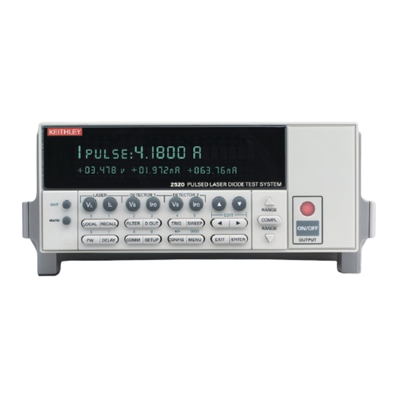
Getting Started Model 2520 User’s Manual Mainframe front and rear panel familiarization Front panel summary The front panel of the Model 2520 mainframe is shown in Figure 1-1. Figure 1-1 Mainframe front panel 2520 PULSED LASER DIODE TEST SYSTEM LASER... -
Page 33: Rear Panel Summary
TRIG External trigger source selected. Output control: ON/OFF OUTPUT Turns the source outputs on or off. Handle: Pull out and rotate to desired position. Rear panel summary The rear panel of the Model 2520 mainframe is shown in Figure 1-2. -
Page 34: Figure 1-2 Mainframe Rear Panel
RS-232 connector: RS-232 Connector for RS-232 remote operation. Use a straight through (not null modem) DB-9 cable such as a Keithley Model 7009-5. GPIB connector: IEEE-488 Connector for GPIB remote operation. Use a shielded cable (Keithley Model 7007-1 or 7007-2). -
Page 35: Testhead Front And Rear Panel Familiarization
Model 2520 User’s Manual Getting Started Testhead front and rear panel familiarization Front panel summary The front panel of the Model 2520 testhead is shown in Figure 1-3. Figure 1-3 Testhead front panel CURRENT OUTPUT CURRENT BIAS INPUT CAT I... -
Page 36: Rear Panel Summary
1-10 Getting Started Model 2520 User’s Manual Rear panel summary The rear panel of the Model 2520 testhead is shown in Figure 1-4. Figure 1-4 Testhead rear panel DISABLED (PULL TO REMOVE) BOTH INTERLOCKS MUST BE ENABLED TO OPERATE REMOTE... -
Page 37: Power-Up
1-11 Power-up Line voltage The Model 2520 operates from a line voltage in the range of 100V to 240V at a frequency of 50 or 60Hz. Line voltage selection is automatic. CAUTION Operating the instrument on an incorrect line voltage may cause dam- age, possibly voiding the warranty. -
Page 38: System Identification
To obtain the serial number and revision information, use the MENU/SERIAL # selection or the *IDN? query via remote. Fuse replacement A rear panel fuse protects the power line input of the Model 2520. If the line fuse needs to be replaced, perform the steps below: WARNING Disconnect the line cord and all cables and test leads from the instru- ment before changing the line fuse. -
Page 39: Display
1-13 Display Display format The Model 2520 display is used primarily to display measured readings and source values. The top line displays source values and the bottom line shows measured values. Display example The following example shows the unit displaying the laser diode source value on the top... -
Page 40: Remote Display Programming
1-14 Getting Started Model 2520 User’s Manual Remote display programming The display can also be controlled by various SCPI :DISPlay subsystem commands. Table 1-2 summarizes the basic command to enable or disable the display. See DISPlay subsystem Section 14 for more information on using this and other display commands. -
Page 41: Restoring Setups
Model 2520 User’s Manual Getting Started 1-15 Restoring setups Press the SETUP key. From the SAVESETUP MENU, select RESTORE, then press ENTER. Select the setup position (0-4) to restore, then press ENTER to complete the pro- cess. Power-on configuration You can also define which of the stored setups (factory default or user) the instrument assumes as the power-on configuration as follows:... -
Page 42: Table 1-3 Factory Default Settings
1-16 Getting Started Model 2520 User’s Manual Table 1-3 Factory default settings Setting BENCH default GPIB default Digital output Level Filter: State Disabled Disabled Average count GPIB address No effect No effect Math function format Resistance Resistance M factor (gain) -
Page 43: Remote Setups
Model 2520 User’s Manual Getting Started 1-17 Table 1-3 (continued) Factory default settings Setting BENCH default GPIB default Sweeps (I only) Type None None Direction Sweep points 1000 1000 Start Stop Step Center Span Triggering Trigger input Event Immediate Immediate... -
Page 44: Main Menu
SAVE Save calibration constants. CHANGE-PASSWORD Change password. TIMESTAMP Reset timestamp (YES or NO). TEST Perform tests on Model 2520. DISPLAY-TESTS Test front panel keys and display digits. KEYS Test front panel keys. DISPLAY-PATTERNS Test display pixels and annunciators. CHAR SET Test special display characters. -
Page 45: Main Operation Menus
Model 2520 User’s Manual Getting Started 1-19 • A measurement or source range is changed by selecting the function by pressing any one of the LASER or DETECTOR function keys and using the RANGE keys. (The unit must be in the edit mode to change the laser diode source range.) Note that when the next higher or lower range is selected, the reading increases or decreases by a decade. -
Page 46: Comm, Setup, And Dig Out Menus
1-20 Getting Started Model 2520 User’s Manual Table 1-5 COMM, SETUP, and DIG OUT menus Menu item Description COMM Select and set up GPIB or RS-232 interface. COMMUNICATIONS SETUP Communications setup menu. GPIB Select and set up GPIB interface. ADDRESS Set primary address (0-30). -
Page 47: Configuration Menus
Model 2520 User’s Manual Getting Started 1-21 Table 1-6 PW, DELAY, and COMPL menus Menu item Description Set laser diode current source (I ) pulse width. PW: 0010.uS Pulse width from 500ns to 5ms.* DELAY Set laser diode current source pulse delay. -
Page 48: Laser And Detector Configuration Menus
1-22 Getting Started Model 2520 User’s Manual Table 1-7 LASER and DETECTOR configuration menus Configuration menu item Description CONFIG LASER V Configure laser diode voltage measurement. CHANNEL1 POLARITY Select laser diode measurement polarity. POSITIVE Select positive measurement polarity. NEGATIVE Select negative polarity. -
Page 49: Trig And Filter Configuration Menus
Model 2520 User’s Manual Getting Started 1-23 Table 1-8 TRIG and FILTER configuration menus Configuration menu item Description CONFIG TRIG Configure triggering. CONFIGURE TRIGGER COUNT Specify trigger count. FINITE Programmable count. INFINITE Never ending count. INIT Enable/disable INIT continuous. Turn on continuous. -
Page 50: Sweep And Math Configuration Menus
1-24 Getting Started Model 2520 User’s Manual Table 1-9 SWEEP and MATH configuration menus Configuration menu item Description CONFIG SWEEP Configure sweeps for laser diode current source (I CONFIGURE SWEEPS TYPE Select sweep type. NONE Disable sweeps. STAIR Linear staircase sweep, program START, STOP and STEP. - Page 51 Interlock connections — Details connections to the remote interlock circuit, which is used to inhibit the outputs with external switching. • Laser diode test connections — Provides detailed diagrams for connecting the Model 2520 signal connectors to the laser diode and photodiodes in a laser diode test system.
-
Page 52: Connection Precautions
Model 2520 User’s Manual Connection precautions WARNING While the Model 2520 does not incorporate a laser, it is designed to operate (power) laser diode devices. Read all safety precautions listed at the beginning of this manual. The following safety practices must be... -
Page 53: Testhead Preparation
Testhead preparation Testhead mounting The Model 2520 has a mounting ear with two holes (2.5 inches on-center) that allow the unit to be mounted in a location convenient to the test fixture. When mounting the testhead, be sure to allow sufficient clearance around the heat sink for proper cooling. -
Page 54: Figure 2-1 Testhead Connections
Connections Model 2520 User’s Manual Figure 2-1 Testhead connections Model 2520 Mainframe WARNING: NO INTERNAL OPERATOR SERVICABLE PARTS, SERVICE BY QUALIFIED PERSONNEL ONLY. IEEE-488 CAT I MADE IN (CHANGE IEEE ADDRESS U.S.A. WITH FRONT PANEL MENU) PULSE DIGITAL I/O SYNC... -
Page 55: Figure 2-2 Testhead Signal Connectors
Model 2520 User’s Manual Connections Signal connectors Signal connectors Figure 2-2 shows the location of the signal connectors on the front panel of the testhead. These connectors are further described below. Figure 2-2 Testhead signal connectors Model 2520 Testhead CURRENT... -
Page 56: Triax Detector Connectors
DUT. Note that the center pin of each connector is signal, while the outer shell is chassis ground. Interlock connections The Model 2520 has two interlock circuits, a remote interlock and a key interlock. NOTE Both interlocks must be enabled to operate. Otherwise the source outputs will not turn on. -
Page 57: Key Interlock
Model 2520 User’s Manual Connections Figure 2-4 Remote interlock connections REMOTE INTERLOCK DISABLED ENABLED Pin 9 Pin 1 Key interlock The key must be inserted into KEY INTERLOCK and rotated to the ENABLED position to operate the unit. Rotate the key to the DISABLED position and remove the key to inhibit the source outputs. -
Page 58: Equivalent Circuit
Polarity considerations All measurements are unipolar. If a particular measurement polarity is set up incorrectly, the Model 2520 will display the “OVERFLOW” message. For detector (I ) measure- ments, current flowing into the ammeter (center conductor of the DETECTOR triax con- nector) is negative, while current flowing out is positive. -
Page 59: Figure 2-6 Equivalent Circuit Of Laser Diode Test Connections
Model 2520 User’s Manual Connections Figure 2-6 Equivalent circuit of laser diode test connections Reverse CURRENT Optional Relay OUTPUT Earth Ground Laser Shorting Diode Relay 12-Bit V-Clamp 12-Bit Coaxial Low DAC Cables 16-Bit Current I-DAC Source -25V VOLTAGE SENSE 14-Bit V-Measure 1MΩ... -
Page 60: Connection Considerations
2-10 Connections Model 2520 User’s Manual Connection considerations When making connections to the laser diode, observe the following considerations to avoid pulse degradation due to distributed inductance and other effects: • Use only the supplied 15Ω coaxial cables. • Keep cable lengths to a minimum. -
Page 61: Basic Operation
Basic Operation • Operation overview — Discusses current and voltage source and measure capabil- ities, ranges, compliance, and fundamental measurement and voltage bias circuit configuration. • Configuring sources — Covers setting up the laser diode current source and photodiode voltage bias source values. •... -
Page 62: Table
• Source Current — The Model 2520 can source DC current to the laser diode from 8µA to 1A (DC or pulse mode), 5.0A (pulse mode only). In the pulse mode, pulse on time (pulse width) is adjustable from 500ns to 5ms in 100ns increments, and pulse off time (pulse delay) is adjustable from 20µs to 500ms in 10µs increments. -
Page 63: Table
Measure Current — Each Model 2520 photodiode channel can measure DC cur- • rents from 0.7µA to 105mA. Each channel has four current ranges: 10mA, 20mA, 50mA, and 100mA. • Source Voltage — Each Model 2520 photodiode bias source can output DC volt- age from 0 to ±20V. -
Page 64: Photodiode Current Measurement Ranges
Basic Operation Model 2520 User’s Manual Photodiode source and measure ranges Table 3-3 summarizes photodiode current measurement ranges, resolutions, and maxi- mum readings. Note that each photodiode voltage bias source has a single 20V range. See Section 6 for more details on ranging. -
Page 65: Figure 3-1 Basic Circuit Configuration
Model 2520 User’s Manual Basic Operation Basic circuit configuration The fundamental circuit configuration for Model 2520 is shown in Figure 3-1. (See Figure 2-6 for a more detailed equivalent circuit.) In addition to the laser diode current source and voltage measurement circuits, the unit has two separate photodiode channels, each of which includes a feedback ammeter and a 0-±20V voltage bias source. -
Page 66: Polarity
Basic Operation Model 2520 User’s Manual Polarity Polarity for the laser diode current source, both detector current measurements, and laser diode voltage measurement can be controlled by using the POLARITY selections in the corresponding configuration menus (see “Configuring sources,” page 3-9, and “Configur-... -
Page 67: Laser Diode Voltage Measurement Polarity
Model 2520 User’s Manual Basic Operation Laser diode voltage measurement polarity Figure 3-3 shows the basic configuration for laser diode voltage measurement polarity. Figure 3-3A shows correct connections for POSITIVE polarity. In this case, the laser diode positive terminal is connected to the VOLTAGE SENSE HI terminal, while the neg- ative laser diode terminal is connected to the VOLTAGE SENSE LO terminal. -
Page 68: Detector Measurement Polarity
Basic Operation Model 2520 User’s Manual Detector measurement polarity Figure 3-4 shows the basic configuration for detector current measurement polarity. With connections shown in Figure 3-4A, current will flow into the current input (center conduc- tor of the triax connector). Under these conditions, the measured current is negative, and the polarity setting must also be NEGATIVE. -
Page 69: Configuring Sources
Model 2520 User’s Manual Basic Operation Configuring sources Follow the general procedures below to set source and compliance values for the laser diode current source as well as bias voltage values for the two photodiode sources. Editing source values Use the following keys to edit source values: •... -
Page 70: Configuring Laser Diode Source
3-10 Basic Operation Model 2520 User’s Manual Configuring laser diode source The basic procedure for setting up laser diode current source values for both DC and pulse modes is outlined below. DC mode Press CONFIG then LASER I to access the source configuration menu. -
Page 71: Pulse Mode
Model 2520 User’s Manual Basic Operation 3-11 Pulse mode Press CONFIG then LASER I to access the source configuration menu. Choose POLARITY, then press ENTER. Select POSITIVE or NEGATIVE as desired, then press ENTER (Figure 3-2). Select SHAPE, then press ENTER. -
Page 72: Configuring Measurements
3-12 Basic Operation Model 2520 User’s Manual Configuring measurements Follow the general procedures below to set the range and polarity for both laser diode and photodiode measurements. NOTE The pulse width setting affects not only the source, but the measurement as well. -
Page 73: Source And Measure Configuration Commands
Model 2520 User’s Manual Basic Operation 3-13 Remote source and measure configuration Source and measure configuration can also be performed via remote by sending appropri- ate commands. The following paragraphs summarize these commands and give a simple programming example. Source and measure configuration commands Table 3-4 summarizes commands used for source and measure configuration. -
Page 74: Table 3-5 Basic Source And Measure Configuration Example
NOTE Section 4 for complete test procedures. These commands set up the Model 2520 as follows: • Laser diode voltage measurement range and polarity: 10V, positive. • Photodiode measurement polarity: negative (both detectors). -
Page 75: Laser Diode Testing
Laser Diode Testing • Source and measure configuration menus — Briefly summarizes the menus for configuring the laser diode source as well as all three measurement functions. • Front panel laser diode testing — Provides a detailed procedure for performing laser diode tests from the front panel. -
Page 76: Table
It is the responsibility of the customer to operate instruments in a safe manner. Follow all applicable safety regulations for installing, config- uring and using the Model 2520. The Model 2520, as installed, should be approved by the appropriate safety personnel, such as the responsi- ble Laser Safety Officer or equivalent. -
Page 77: Figure 4-1 Circuit Configuration For Laser Diode Testing
Model 2520 User’s Manual Laser Diode Testing Front panel laser diode testing Test circuit configuration The basic circuit configuration for the laser diode test procedures in this section is shown Figure 4-1. (See Figure 2-5 for a more detailed drawing.) Note that connections for laser diode as well as both photodiode detectors are included, but the required interlock connections are not shown. -
Page 78: Front Panel Test Procedure
Laser Diode Testing Model 2520 User’s Manual Front panel test procedure Step 1: Configure laser diode measurement function. Configure the laser diode measurement function as follows: Press CONFIG then LASER V Choose POSITIVE or NEGATIVE polarity as desired, then press ENTER. -
Page 79: Laser Diode Test Commands
Model 2520 User’s Manual Laser Diode Testing Press DETECTOR 2 V to select the photodiode #2 source. Again, using either the EDIT or numeric entry keys, set the bias source value to the desired value. Step 5: Configure math functions. -
Page 80: Table 4-2 Laser Diode Test Commands
Laser Diode Testing Model 2520 User’s Manual Table 4-2 Laser diode test commands Command Description :CALCulate[1]:FORMat <format> Define laser diode math format (MXB[1], CONDuctance[1]), POWER[1], or RESistance[1]). :CALCulate[1]:DATA? Request laser diode math reading. :CALCulate[1]:STATe <state> Enable/disable laser diode math (ON or OFF). -
Page 81: Programming Example
Figure 4-1 for basic circuit configuration and Section 2 for detailed connection infor- mation. These commands set up the Model 2520 as follows: • Laser diode voltage measurement range and polarity: 10V, positive. • Detector measurement polarity: negative (both detectors). -
Page 82: Table 4-3 Basic Laser Diode Test Command Sequence
Laser Diode Testing Model 2520 User’s Manual NOTE Appendix H for a functional program example. Table 4-3 Basic laser diode test command sequence Step Action Commands Comments *RST Restore GPIB defaults. Configure laser diode measure. :SENS1:VOLT:RANG 10 LD measure range = 10V. - Page 83 Source-Measure Concepts • Pulse concepts — Describes the various aspects of the laser diode current source pulse mode. • Sweep operation — Covers the various types of sweeps that can be performed. • Operating boundaries — Covers output and limit operating boundaries for the laser diode current source.
-
Page 84: Figure 5-1 Delay-Pulse Cycle
Source-Measure Concepts Model 2520 User’s Manual Pulse concepts Overview The Model 2520 laser diode current source can output either DC or pulse waveforms. Maximum current is as follows: • DC: 1A • Pulse mode: 5A In addition, the current source can be operated in either the fixed or sweep mode. In the fixed mode, the source simply outputs the programmed DC level (DC mode), or pulses at... -
Page 85: Delay Phase
× ---------------------- - Where: DC = duty cycle (%) PW = pulse width (s) PD = pulse delay (s) NOTE The Model 2520 will not output pulses at a duty cycle larger than 4% for cur- rents more than 1A. -
Page 86: Front Panel Pulse Parameters
Source-Measure Concepts Model 2520 User’s Manual Front panel pulse parameters Fixed mode Figure 5-2 shows how various front panel programming parameters control various fixed pulse waveform aspects. These parameters are programmed by pressing the appropriate key: • LASER I — sets the pulse amplitude. -
Page 87: Figure 5-3 Front Panel Staircase Sweep Mode Pulse Parameters
Model 2520 User’s Manual Source-Measure Concepts Figure 5-3 Front panel staircase sweep mode pulse parameters Stop Step Start Delay Returns to 0A because pulse is less than Low. Figure 5-4 shows how various front panel programming parameters control various stair- case sweep DC waveform aspects. -
Page 88: Remote Pulse Parameters
Source-Measure Concepts Model 2520 User’s Manual Remote pulse parameters Fixed mode Figure 5-5 shows how various remote commands control various fixed pulse waveform aspects. These parameters are programmed as follows: • SOUR1:CURR — sets the pulse amplitude. • SOUR1:PULS :DEL — sets the pulse delay (time between pulses). -
Page 89: Pulse Rise And Fall Times
Model 2520 User’s Manual Source-Measure Concepts Figure 5-6 Remote staircase sweep mode pulse parameters SOUR1:CURR:STOP SOUR1:CURR:STEP SOUR1:CURR:LOW Start SOUR1:CURR:START SOUR1:PULS:DEL SOUR1:PULS:WIDT Returns to 0A because pulse is less than Low. Pulse rise and fall times As shown in Figure 5-7, there are two additional pulse characteristics that require discus- sion: rise time and fall time. -
Page 90: Sweep Waveforms
Source-Measure Concepts Model 2520 User’s Manual Sweep waveforms There are three basic sweep types available: linear staircase, logarithmic staircase, and custom. NOTE Staircase sweeps can be programmed both from the front panel and via remote, while custom sweeps are available only via remote. -
Page 91: Figure 5-9 Custom Sweep Waveform
Model 2520 User’s Manual Source-Measure Concepts Figure 5-8 Sweep waveform types Stop Start Linear Staircase Sweep Stop Start Logarithmic scale shown for staircase steps. Logarithmic Staircase Sweep First Point Last Point Custom Sweep Note: DC mode waveforms shown. Figure 5-9... -
Page 92: Current Source Operating Boundaries
DUT load line for 125Ω intersects the 10.5V compliance limit line placing the Model 2520 in compliance. In compliance, the Model 2520 will not be able to source its pro- grammed current (100mA). For the 125Ω DUT, the unit will output only 80mA (at the... -
Page 93: Figure 5-11 Loading Effects
Model 2520 User’s Manual Source-Measure Concepts 5-11 Figure 5-11 Loading effects Voltage Limit Load Line 10.5V Output Voltage (V) Operating Point Current Source Load Line 100mA Output Current (mA) V = I • R = (100mA)(50Ω) = 5V A. Normal Current Source Operation... -
Page 94: Data Flow
Notice that as resistance increases, the slope of the DUT load line increases. As resistance approaches infinity (open output), the Model 2520 will source virtually 0mA at 10.5V. Conversely, as resistance decreases, the slope of the DUT load line decreases. At zero resistance (shorted output), the Model 2520 will source virtually 100mA at 0V. -
Page 95: Figure 5-12 Data Flow-Front Panel
Model 2520 User’s Manual Source-Measure Concepts 5-13 Figure 5-12 Data flow-front panel Laser Voltage and Display Normal Detector Current Voltage and Current Functions Readings A. Math Function and Sweeps Disabled Display Math Math Function Readings Function B. Math Function Enabled... -
Page 96: Range, Filter, And Math
Range, Filter, and Math • Range — Discusses available ranges, maximum readings and source values, and ranging limitations. • Filter — Provides information on the filtering process that can be used to reduce reading noise. • Math — Outlines the math functions that can be performed on laser diode voltage measurement and photodiode current measurement data. -
Page 97: Table
±10.5V Photodiode detector current ranges Table 6-2 lists the available current measurement ranges, resolution values, and maximum readings for each Model 2520 photodiode detector. NOTE The current measurement range can be individually set for each detector. Table 6-2 Photodiode current measurement ranges... -
Page 98: Table
Model 2520 User’s Manual Range, Filter, and Math Maximum readings The full scale input for each measurement range is shown in Table 6-1 Table 6-2. Input levels that exceed the maximum levels cause the “Oflow” message to be displayed. Setting the measurement range... -
Page 99: Range Programming Example
Range, Filter, and Math Model 2520 User’s Manual Range programming example Table 6-5 shows a programming example for controlling range. The Model 2520 is set up as follows: • Laser diode voltage measure range: 5V. • Laser diode current source range: 500mA. -
Page 100: Filter Configuration
Model 2520 User’s Manual Range, Filter, and Math Figure 6-1 Averaging filter during sweep 30mA Step Start = 10mA Stop = 30mA Step = 10mA 20mA Step 10mA Step With filter count = 3, three delay-pulse cycles are performed at each sweep step. -
Page 101: Table 6-6 Filter Commands
Filter programming example Command Description :AVER:COUN 20 Set average count to 20. :AVER ON Enable average filter. Measurement math functions The Model 2520 has built-in math functions to calculate the following: • Conductance • Resistance • MX + B •... -
Page 102: Conductance
Model 2520 User’s Manual Range, Filter, and Math Conductance This math function computes the conductance from the ratio between the laser diode cur- rent source value and the measured voltage: Conductance = I where: = laser diode source current = measured laser diode voltage... -
Page 103: Math Configuration Menu
Range, Filter, and Math Model 2520 User’s Manual Front panel math functions Math configuration menu Table 6-8 summarizes the math configuration menu. Press CONFIG then MATH to access the menu. Table 6-8 Math configuration menu Configuration menu item Description CONFIGURE MATH... -
Page 104: Math Function Commands
Model 2520 User’s Manual Range, Filter, and Math Remote math functions Math function commands Table 6-9 summarizes commands to control the measurement math functions by remote. “Calculate subsystems,” page 14-14, for detailed information. Table 6-9 Math function commands Command Description :CALCulate[1]:DATA? Request laser diode math reading. -
Page 105: Math Function Programming Example
6-10 Range, Filter, and Math Model 2520 User’s Manual Math function programming example Table 6-10 summarizes commands that program the following math function parameters: • Laser diode math function: power • Detector #1 MX + B slope (M): 0.5 •... -
Page 106: Sweep Operation
Sweep Operation • Sweep types — Describes the three basic sweep types: Linear staircase, logarith- mic staircase, and custom sweep. • Configuring and running a sweep — Discusses the procedure for setting up and performing sweeps including selecting and configuring a sweep and performing a sweep. -
Page 107: Figure 7-1 Linear Staircase Sweep
Sweep Operation Model 2520 User’s Manual Sweep types The three basic sweep types described in the following paragraphs include: • Linear staircase • Logarithmic staircase • Custom NOTE Linear and logarithmic staircase sweeps are available both from the front panel and via remote. -
Page 108: Figure 7-2 Logarithmic Staircase Sweep
Model 2520 User’s Manual Sweep Operation Logarithmic staircase sweep This sweep is similar to the linear staircase sweep. The steps, however, are done on a loga- rithmic scale as shown in the example sweep in Figure 7-2. This is a 5-point log sweep from 1mA to 10mA. -
Page 109: Figure 7-3 Custom Pulse Sweep
Sweep Operation Model 2520 User’s Manual Thus, the five log steps for this sweep are 0, 0.25, 0.50, 0.75, and 1.00mA. The actual cur- rent source levels at these points are listed in Table 7-1 (the current level is the anti-log of the log step). -
Page 110: Configuring And Running A Sweep
Model 2520 User’s Manual Sweep Operation Configuring and running a sweep Front panel sweep operation Configuring a sweep The sweep configuration menu is structured as follows and shown in Figure 7-4. Note that bullets indicate the primary items of the sweep menu and dashes indicate the options of each menu item. -
Page 111: Performing Sweeps
Model 2520 User’s Manual Performing sweeps Procedures for the various sweep types are covered below. NOTE The following procedure assumes that the Model 2520 is already connected to the DUT as explained in Section Performing a linear staircase sweep Step 1: Configure source and measure. -
Page 112: Performing A Log Staircase Sweep
Model 2520 User’s Manual Sweep Operation Performing a log staircase sweep Step 1: Configure source and measure. Configure the Model 2520 source and measure functions as follows: Select the current source range by pressing LASER I then EDIT, then use the RANGE keys. -
Page 113: Table
Sweep Operation Model 2520 User’s Manual Remote sweep operation Staircase sweep commands Table 7-2 summarizes remote commands used for linear and log staircase sweep opera- tion. See Section “Configure sweeps,” for more details on these commands. Table 7-2 Linear and log staircase sweep commands... -
Page 114: Table 7-3 Linear Staircase Sweep Programming Example
Model 2520 User’s Manual Sweep Operation Staircase sweep programming example As an example of linear staircase sweep operation, assume the Model 2520 is to be used to test a laser diode. For the purposes of this test, assume the following basic sweep parameters: •... -
Page 115: Custom Sweep Commands
7-10 Sweep Operation Model 2520 User’s Manual Custom sweep commands Table 7-4 summarizes remote commands used for custom sweep operation. See Section “Configure list,” for more details on these commands. Table 7-4 Custom sweep commands Command Description :SOURce[1]:CURRent:MODE LIST Select current list (custom) sweep mode. -
Page 116: Table 7-5 Custom Sweep Programming Example
Model 2520 User’s Manual Sweep Operation 7-11 Table 7-5 summarizes the basic remote command sequence for performing the custom sweep described above. Table 7-5 Custom sweep programming example Command Description *RST Restore GPIB default conditions. :FORM:ELEM VOLT1,CURR2,CURR3 Laser diode voltage, detector current data. -
Page 117: Triggering
Triggering • Trigger model — Discusses the trigger model, including various layers, input trig- gers, and output trigger. • Trigger link — Discusses the trigger link, including input triggers and output trig- gers. • Configuring triggering — Details how to configure the various triggering aspects from the front panel. -
Page 118: Trigger Model (Front Panel Operation)
The trigger model consists of an Idle Layer and a Trigger Layer to provide versatility. A programmable counter allows operations to be repeated, and various input and output trig- ger options are available to provide synchronization between the Model 2520 and other instruments (via the Trigger Link). -
Page 119: Idle Layer
Triggering Idle layer The Model 2520 is in the Idle Layer when it is not operating in the Trigger Layer of the trigger model. The Model 2520 can be returned to idle at any time by selecting the HALT menu item of the CONFIGURE TRIGGER menu. See “Configuring triggering,”... -
Page 120: Pulse Phase
5000. Output trigger The Model 2520 can be programmed to output a trigger (via rear panel Trigger Link con- nector) after various trigger model operations. An output trigger is used to trigger another instrument to perform an operation. -
Page 121: Figure 8-2 Rear Panel Pinout
Timer = 0.1s • Trigger Out Event = Off Unless programmed otherwise, the Model 2520 will run in a continuous loop around the trigger model, processing one set of readings each time it goes through the loop. Operation summary The trigger model is designed to offer versatility for the various source and measure appli- cations. -
Page 122: Input Trigger Requirements
TTL Low (0.8V) 10µs Output trigger specifications The Model 2520 can be programmed to output a trigger after various trigger model actions. See “Trigger model (front panel operation),” page 8-2. The output trigger provides a TTL-compatible output pulse that can be used to trigger other instruments. The specifi-... -
Page 123: Configuring Triggering
PULSE mode is selected, or if a front panel sweep is initiated. HALT — Use to return the Model 2520 to the idle state. HALT does not turn off • the output. The programmed source levels will still be available at the OUTPUT terminals. -
Page 124: Figure 8-5 Configure Trigger Menu Tree
Triggering Model 2520 User’s Manual ↓STEST — Event detection occurs when the SOT line of the Digital I/O port • is pulsed low (See Section ↑STEST — Event detection occurs when the SOT line of the Digital I/O port •... -
Page 125: Remote Triggering
The trigger model consists of two layers (Idle Layer and Trigger Layer) to provide versa- tility. A programmable counter allows operations to be repeated, and various input and output trigger options are available to provide synchronization between the Model 2520 and other instruments (via the Trigger Link). -
Page 126: Figure 8-6 Trigger Model (Remote Operation)
8-10 Triggering Model 2520 User’s Manual Figure 8-6 Trigger model (remote operation) See Note Note: The following commands place the Model 2520 into idle: DCL, SDC, ABORt, *RST, SYSTem:PREset, and *RCL. INITiate Idle Turn On Outputs Trigger Layer TRIGger:SOURce Another TRIGger:COUNt ✛... -
Page 127: Event Detection
The timer resets to its initial state when the instrument goes into idle. MANual — Event detection occurs when the TRIG key is pressed. The Model 2520 must be in LOCAL mode for it to respond to the TRIG key. Press the LOCAL key or send GTL over the bus to take the Model 2520 out of remote. -
Page 128: Delay And Pulse Phases
8-12 Triggering Model 2520 User’s Manual Delay and pulse phases The delay-pulse cycle consists of two phases: Delay and Pulse. (See Section 5 for details.) Delay phase The programmable delay is the time period between current pulses. The delay is set with the :DELay commands and can be programmed in the range of 20µs to 500ms. -
Page 129: Remote Trigger Commands
• Enabled output trigger = None With outputs turned ON (OUTP1 ON), the Model 2520 will perform one measurement cycle when the INITiate command is sent. After the measurement, the Model 2520 returns to the idle state. Operation summary The trigger model is designed to offer versatility for the various source and measure appli- cations. -
Page 130: Table
*TRG Trigger Model 2520 (if BUS source selected). Remote trigger example Table 8-2 summarizes the command sequence for basic trigger operation. These com- mands set up Model 2520 triggering as follows: • Trigger input source: bus • Output trigger: enabled •... - Page 131 Digital I/O Port, Interlocks, and Pulse Sync Output • Digital I/O Port — Discusses the various input/output lines on the Digital I/O Port as well as the +5V line that can be used to power external logic circuits. • Interlocks — Describes how to use to determine the status of the interlocks. •...
-
Page 132: Figure 9-1 Digital I/O Port
Digital I/O Port, Interlocks, and Pulse Sync Output Model 2520 User’s Manual Digital I/O port The Model 2520 has a digital input/output port that can be used to control external digital circuitry. Port configuration The Digital I/O Port is located on the rear panel and is shown in Figure 9-1. -
Page 133: Figure 9-2 Sink Operation
Model 2520 User’s Manual Digital I/O Port, Interlocks, and Pulse Sync Output Start-of-test (SOT) line The input line (SOT) is a TTL-compatible logic line used by external equipment to start a test. With the ↓STEST trigger event selected, a low SOT pulse starts the testing process. -
Page 134: Figure 9-3 Source Operation
Digital I/O Port, Interlocks, and Pulse Sync Output Model 2520 User’s Manual Source operation Figure 9-3 shows the basic output configuration for source operation. In this case, the external relay coil is connected between the digital output line (pins 1 to 4) and ground (pin 9). -
Page 135: Table
H = High (>+3V) Interlocks The Model 2520 testhead is equipped with two interlock protection devices. The REMOTE INTERLOCK connector is a DB-9 connector intended for such applications as a remote interlock switch, while the KEY INTERLOCK connector is intended for connec- tions for a security key switch. -
Page 136: Figure 9-4 Interlock Operation
Interlock operation Model 2520 Testhead Test Fixture Pin 1 Remote Interlock Switch Interlock Closed Pin 9 A. Model 2520 outputs can be turned on. Model 2520 Testhead Test Fixture Pin 1 Remote Interlock Switch Interlock Open Pin 9 B. Model 2520 outputs cannot be turned on. -
Page 137: Interlock Status Indicator Test Sequence
If at any time the indicators provided on the testhead, for INTER- LOCK STATUS or LASER POWER ON, should fail to light or to properly indicate status, immediately contact a Keithley service repre- sentative for repair. Failure to do so may expose the user to hazards without proper warnings. -
Page 138: Pulse Sync Output
Digital I/O Port, Interlocks, and Pulse Sync Output Model 2520 User’s Manual Pulse sync output The Model 2520 has a pulse sync output that allows synchronization of external equip- ment to the laser diode current source pulse. Pulse sync waveform Figure 9-5 shows the pulse sync waveform, which is a 5V pulse with 50Ω... -
Page 139: Pulse Sync Connections
Model 2520 User’s Manual Digital I/O Port, Interlocks, and Pulse Sync Output Pulse sync connections Figure 9-6 shows typical pulse sync connections. Use quality BNC 50Ω RG-58 cable to avoid pulse distortion that could cause timing and jitter problems. Figure 9-6... -
Page 140: Remote Operations
LOCAL key. • Programming syntax — Describes the basic programming syntax for both com- mon and SCPI commands. • RS-232 interface operation — Outlines use of the RS-232 interface to control the Model 2520 via remote. -
Page 141: Differences: Remote Vs. Local Operation
Differences: remote vs. local operation Local-to-remote transition When changing from local to remote operation, the following takes place: • The Model 2520 stops taking readings and is placed into the Idle layer of the Trig- ger Model. • All menus are exited. -
Page 142: Gpib Operation
The above standards define a syntax for sending data to and from instruments, how an instrument interprets this data, what registers should exist to record the state of the instru- ment, and a group of common commands. The Model 2520 also conforms to this standard: •... -
Page 143: Gpib Connections
10-4 Remote Operations Model 2520 User’s Manual GPIB connections To connect the Model 2520 to the GPIB bus, use a cable equipped with standard IEEE-488 connectors as shown in Figure 10-1. Figure 10-1 IEEE-488 connector To allow many parallel connections to one instrument, stack the connectors. Two screws are located on each connector to ensure that connections remain secure. -
Page 144: Figure 10-3 Ieee-488 And Rs-232 Connector Location
IEEE-488 cables. Available shielded cables from Keithley are Models 7007-1 and 7007-2. To connect the Model 2520 to the IEEE-488 bus, follow these steps: Line up the cable connector with the connector located on the rear panel. The con- nector is designed so it will fit only one way. -
Page 145: Table 10-1 General Bus Commands
Model 2520 User’s Manual Primary address The Model 2520 ships from the factory with a GPIB primary address of 25. When the unit powers up, it momentarily displays the primary address. You can set the address to a value from 0 to 30, but do not assign the same address to another device or to a controller that is on the same GPIB bus (controller addresses are usually 0 or 21). -
Page 146: Ren (Remote Enable)
:MEASure? IFC (interface clear) The IFC command is sent by the controller to place the Model 2520 in the local, talker, lis- tener idle states. The unit responds to the IFC command by cancelling front panel TALK or LSTN lights if the instrument was previously placed in one of these states. -
Page 147: Sdc (Selective Device Clear)
DCL. GET (group execute trigger) GET is a GPIB trigger that is used as a trigger event to control operation. The Model 2520 reacts to this trigger if it is the programmed trigger control source. The following com-... -
Page 148: Gpib Status Indicators
Clear) command. LSTN This indicator is on when the Model 2520 is in the listener active state, which is activated by addressing the instrument to listen with the correct MLA (My Listen Address) com- mand. LSTN is off when the unit is in the listener idle state. Place the unit in the listener idle state by sending UNL (Unlisten), addressing it to talk, or sending IFC (Interface Clear) command over the bus. -
Page 149: Programming Syntax
10-10 Remote Operations Model 2520 User’s Manual Programming syntax The information in this section covers syntax for both common commands and SCPI com- mands. For information not covered here, see the IEEE-488.2 and SCPI standards. See Section 12 Section 14 for more details on common and SCPI commands, respectively. - Page 150 Model 2520 User’s Manual Remote Operations 10-11 Example: <name> = NONE :TRIGger:OUTPut NONE <NRf> Numeric representation format — This parameter is a number that can be expressed as an integer (e.g., 8), a real number (e.g., 23.6), or an exponent (2.3E6).
-
Page 151: Query Commands
10-12 Remote Operations Model 2520 User’s Manual Query commands This type of command requests (queries) the presently programmed status. It is identified by the question mark (?) at the end of the fundamental form of the command. Most com- mands have a query form: :SOURce1:PULSe:DELay? Queries the pulse delay. -
Page 152: Short-Form Rules
Model 2520 User’s Manual Remote Operations 10-13 Short-form rules Use the following rules to determine the short-form version of any SCPI command: • If the length of the command word is four letters or less, no short form version exists. Example: •... -
Page 153: Multiple Command Messages
10-14 Remote Operations Model 2520 User’s Manual :stat:oper:enab <NRf> :stat:oper:enab? :stat:pres In each of the above program messages, the path pointer starts at the root command (:stat) and moves down the command levels until the command is executed. Multiple command messages You can send multiple command messages in the same program message as long as they are separated by semicolons (;). -
Page 154: Using Common And Scpi Commands In The Same Message
Model 2520 is addressed to talk. The responses are sent in the order the query commands were sent and are separated by semicolons (;). Items within the same query are separated by commas (,). -
Page 155: Response Message Terminator (Rmt)
>11 bits). This clears any pending operation, discards any pending output, and returns a “DCL.” Baud rate The baud rate is the rate at which the Model 2520 and the programming terminal commu- nicate. Choose one these available rates: •... -
Page 156: Data Bits And Parity
When you choose a baud rate, make sure the programming terminal or printer that you are connecting to the Model 2520 can support the baud rate you selected. Both the Model 2520 and the other device must be configured for the same baud rate. -
Page 157: Rs-232 Connections
Remote Operations Model 2520 User’s Manual If NONE is the selected flow control, there will be no signal handshaking between the controller and the Model 2520. Data will be lost if transmitted before the receiving device is ready. RS-232 connections... -
Page 158: Table 10-3 Pc Serial Port Pinout
Model 2520 User’s Manual Remote Operations 10-19 Table 10-2 RS-232 connector pinout Pin number Description Not used TXD, transmit data RXD, receive data Not used GND, signal ground Not used RTS, ready to send CTS, clear to send Not used Note: CTS and RTS are tied together. -
Page 159: Error Messages
The following QuickBasic 4.5 programming example will control the Model 2520 via the RS-232 COM2 port. Place the Model 2520 into the RS-232 mode from the front panel main menu (press COMM then select RS-232). When the communication setting is changed, the Model 2520 will reset into that mode. -
Page 160: Status Structure
Status Structure • Overview — Provides an operational overview of the status structure for the Model 2520. • Clearing registers and queues — Covers the actions that clear (reset) registers and queues. • Programming and reading registers — Explains how to program enable registers and read any register in the status structure. -
Page 161: Overview
Status Structure Model 2520 User’s Manual Overview The Model 2520 provides a series of status registers and queues allowing the operator to monitor and manipulate the various instrument events. The status structure is shown in Figure 11-1. The heart of the status structure is the Status Byte Register. This register can be read by the user's test program to determine if a service request (SRQ) has occurred, and what event caused it. -
Page 162: Figure 11-1 Model 2520 Status Register Structure
Model 2520 User’s Manual Status Structure 11-3 Figure 11-1 Model 2520 status register structure Questionable Questionable Questionable Event Condition Event Enable Register Register Register & & & & & & & Logical & Calibration Summary & & Error Queue &... -
Page 163: Table
Model 2520 User’s Manual Clearing registers and queues When the Model 2520 is turned on, the bits of all registers in the status structure are cleared (reset to 0), and the two queues are empty. Commands to reset the event and event... -
Page 164: Figure 11-2 16-Bit Status Register
Model 2520 User’s Manual Status Structure 11-5 Programming and reading registers Programming enable registers The only registers that can be programmed by the user are the enable registers. All other registers in the status structure are read-only registers. The following explains how to ascertain the parameter values for the various commands used to program enable registers. -
Page 165: Reading Registers
11-6 Status Structure Model 2520 User’s Manual The <NDN> (non-decimal numeric) parameter type is used to send non-decimal values. These values require a header (#B, #H, or #Q) to identify the data format being sent. The letter in the header can be upper or lower case. The <NRf> (numeric representation for- mat) parameter type is used to send decimal values, and does not use a header. -
Page 166: Status Byte And Service Request (Srq)
Model 2520 User’s Manual Status Structure 11-7 Table 11-2 Data format commands for reading status registers Command Description Default :FORMat:SREGister <name> Select data format for reading status registers: ASCii <name> = ASCii Decimal format HEXadecimal Hexadecimal format OCTal Octal format... -
Page 167: Status Byte Register
Service (RQS) bit or the Master Summary Status (MSS) bit: • When using the serial poll sequence of the Model 2520 to obtain the status byte (a.k.a. serial poll byte), B6 is the RQS bit. See “Serial polling and SRQ,” page 11-9 for details on using the serial poll sequence. -
Page 168: Serial Polling And Srq
Typically, SRQs are managed by the serial poll sequence of the Model 2520. If an SRQ does not occur, bit B6 (RQS) of the Status Byte Register will remain cleared, and the pro- gram will simply proceed normally after the serial poll is performed. -
Page 169: Table
11-10 Status Structure Model 2520 User’s Manual Status byte and service request commands The commands to program and read the Status Byte Register and Service Request Enable Register are listed in Table 11-3. For details on programming and reading registers, see “Programming enable registers,”... -
Page 170: Status Register Sets
Bit B6, User Request (URQ) — Set bit indicates that the LOCAL key on the Model 2520 front panel was pressed. • Bit B7, Power ON (PON) — Set bit indicates that the Model 2520 has been turned off and turned back on since the last time this register has been read. -
Page 171: Figure 11-4 Standard Event Status
11-12 Status Structure Model 2520 User’s Manual Figure 11-4 Standard event status — — Standard Event *ESR? (B15 Status Register –B8) (B7) (B6) (B5) (B4) (B3) (B2) (B1) (B0) & & & & & & & To Event *ESE —... -
Page 172: Figure 11-5 Operation Event Status
TLINK trigger event to occur. • Bits B6 through B9 — Not used. • Bit B10, Idle State (Idle) — Set bit indicates the Model 2520 is in the idle state. • Bits B11 through B15 — Not used. Figure 11-5 Operation event status —... -
Page 173: Measurement Event Register
11-14 Status Structure Model 2520 User’s Manual Measurement event register The used bits of the Measurement Event Register (shown in Figure 11-6) are described as follows: • Bit B0 — Not used. • Bit B1, HW Interlock (INT) — Set bit indicates that the hardware interlock line on the testhead is at a digital low (asserted). -
Page 174: Figure 11-6 Measurement Event Status
Model 2520 User’s Manual Status Structure 11-15 Figure 11-6 Measurement event status Measurement Condition Register stat:meas:cond? — (B4) (B15) (B9) (B8) (B7) (B6) (B5) (B3) (B2) (B1) (B0) (B14) (B11) (B10) (B13) (B12) stat:meas? — (B4) (B15) (B9) (B8) (B7) -
Page 175: Questionable Event Register
11-16 Status Structure Model 2520 User’s Manual Questionable event register The used bits of the Questionable Event Register (shown in Figure 11-7) are described as follows: • Bits B0 through B7 — Not used. • Bit B8, Calibration Summary (Cal) — Set bit indicates that an invalid calibration constant was detected during the power-up sequence. -
Page 176: Table
For example, while the Model 2520 is in the idle state, bit B10 (Idle) of the Operation Condition Register will be set. When the instrument is taken out of idle, bit B10 clears. -
Page 177: Event Enable Registers Commands
11-18 Status Structure Model 2520 User’s Manual Event enable registers Figure 11-1 shows, each status register set has an enable register. Each event register bit is logically ANDed (&) to a corresponding enable bit of an enable register. Therefore, when an event bit is set and the corresponding enable bit is set (as programmed by the user), the output (summary) of the register will set to 1, which in turn sets the summary bit of the Status Byte Register. -
Page 178: Program And Read Register Programming Example
Output Queue is considered cleared when it is empty. An empty Output Queue clears the MAV bit in the Status Byte Register. A message is read from the Output Queue by addressing the Model 2520 to talk after the appropriate query is sent. -
Page 179: Error Queue
Error Queue is empty. When empty, the message “0, No Error” is placed in the queue. Messages in the Error Queue are preceded by a code number. Negative (-) numbers are used for SCPI-defined messages, and positive (+) numbers are used for Keithley-defined messages. The messages are listed in Appendix B. -
Page 180: Table 11-9 Error Queue Commands
Model 2520 User’s Manual Status Structure 11-21 Table 11-9 Error queue commands Command Description Default STATus STATus Subsystem: :QUEue Read Error Queue: Note 1 [:NEXT]? Read and clear oldest error/status (code and message). :ENABle <list> Specify error and status messages for Error Queue. -
Page 181: Common Commands
Common Commands • Command summary — Lists the IEEE-488.2 common commands used by the Model 2520. • Command reference — Provides a detailed reference for all common commands except for those associated with the status structure, which are discussed in... -
Page 182: Table
Query Model 2520 for list of installed options. *RCL <NRf> Recall command Returns the Model 2520 to the user-saved setup. *RST Reset command Returns the Model 2520 to the *RST default condi tions. *SAV <NRf> Save command Saves the present setup as the user-saved setup. *SRE <NRf>... -
Page 183: Command Reference
Reads identification code The identification code includes the manufacturer, model number, serial number, and firm- ware revision levels and is sent in the following format: KEITHLEY INSTRUMENTS INC., MODEL 2520, xxxxxxx, yyyyyyy, zzzzz mmm ddd yyyy ++:++:++ /aaa/bbb/c/d/e Where: xxxxxxx is the mainframe serial number. -
Page 184: Opc Programming Example
* Additional code required to test for “1” in Output Queue. *OPT? — option query Return list of installed options When *OPT? is sent, Model 2520 returns a list of any installed options. *SAV <NRf> — save Save present setup in memory *RCL <NRf>... -
Page 185: Sav, *Rcl Programming Example
*TRG — trigger Send bus trigger to Model 2520 Use the *TRG command to issue a GPIB trigger to the Model 2520. It has the same effect as a group execute trigger (GET). Use the *TRG command as an event to control operation. The Model 2520 reacts to this trigger if BUS is the programmed arm control source using the :TRIG:SOUR BUS com- mand. -
Page 186: Tst? — Self-Test Query
Use this query command to perform a checksum test on ROM. The command places the coded result (0 or 1) in the Output Queue. When the Model 2520 is addressed to talk, the coded result is sent from the Output Queue to the computer. -
Page 187: Scpi Signal-Oriented Measurement Commands
SCPI Signal-Oriented Measurement Commands • Command summary — Summarizes those commands used to acquire readings. • Acquiring readings — Describes commands to acquire post-processed readings, both trigger and acquire readings, and to perform a single measurement. -
Page 188: Table
This query command requests the latest post-processed readings stored in the reading buffer. After sending this command and addressing the Model 2520 to talk, the readings are sent to the computer. This com- mand does not affect the instrument setup. -
Page 189: Sense[1]]:Data[:Latest]?
SCPI Signal-Oriented Measurement Commands 13-3 NOTE Appendix C for a detailed explanation on how data flows through the vari- ous operation blocks of the Model 2520. It clarifies the types of readings that are acquired by the various commands to read data. [:SENSe[1]]:DATA[:LATest]? [:SENSe2]:DATA[:LATest]? -
Page 190: Scpi Command Reference
SCPI Command Reference • Reference tables — Summarizes each SCPI command subsystem. • SCPI subsystems — Provides detailed information on all commands in each SCPI subsystem. -
Page 191: Reference Tables
14-2 SCPI Command Reference Model 2520 User’s Manual Reference tables Table 14-1 through Table 14-10 summarize the commands for each SCPI subsystem. The following list includes the SCPI subsystem commands and the table number where each command is summarized. Summary table... -
Page 192: Table
Model 2520 User’s Manual SCPI Command Reference 14-3 Table 14-1 CALCulate command summary Default Command Description parameter SCPI :CALCulate[1] Path to configure and control laser diode math: :DATA Path to CALC1 data. :LATest? Return only most recent math result. :DATA? Read result of math generated by INIT. - Page 193 14-4 SCPI Command Reference Model 2520 User’s Manual Table 14-1 (continued) CALCulate command summary Default Command Description parameter SCPI :CALCulate3 Path to configure and control detector #2 math: :DATA Path to CALC3 data. :LATest? Return only most recent math result.
-
Page 194: Table
Model 2520 User’s Manual SCPI Command Reference 14-5 Table 14-2 DISPlay command summary Default Command Description parameter SCPI :DISPlay :ENABle <b> Turn on or turn off front panel display. Note 1 :ENABle? Query state of display. [:WINDow[1]] Path to locate message to top display line:... -
Page 195: Table
14-6 SCPI Command Reference Model 2520 User’s Manual Table 14-3 FORMat command summary Default Command Description parameter SCPI :FORMat :SREGister <name> Select data format for reading status event registers (ASCii, HEXadecimal, OCTal, or BINary). :SREGister? Query format for reading status event registers. -
Page 196: Table 14-5 Sense Command Summary
Model 2520 User’s Manual SCPI Command Reference 14-7 Table 14-5 SENSe command summary Default Command Description parameter SCPI [:SENSe[1]] Sense 1 subsystem to control laser diode voltage measurement: :VOLTage[:DC] Path to configure voltage: :RANGe Configure measurement range: [:UPPer] <n> Select range by specifying the expected voltage reading;... - Page 197 14-8 SCPI Command Reference Model 2520 User’s Manual Table 14-5 (continued) SENSe command summary Default Command Description parameter SCPI :SENSe3 Sense 3 subsystem to control detector #2 current measurement: :CURRent[:DC] Path to configure current: :RANGe Configure measurement range: [:UPPer] <n>...
- Page 198 Model 2520 User’s Manual SCPI Command Reference 14-9 Table 14-6 SOURce command summary Default Command Description parameter SCPI :SOURce[1] Path to control laser diode current source: :CLEar[:IMMediate] Turn all three sources off. :CURRent Path to configure current: :MODE <name> Select mode (FIXed, SWEep, or LIST).
-
Page 199: Table 14-6 Source Command Summary
14-10 SCPI Command Reference Model 2520 User’s Manual Table 14-6 (continued) SOURce command summary Default Command Description parameter SCPI :SOURce[1] Path to control laser diode current source (continued): :VOLTage Path to set compliance level. :PROTection [:LEVel] <NRf> Set voltage limit; 3 to 10.5. - Page 200 Model 2520 User’s Manual SCPI Command Reference 14-11 Table 14-6 (continued) SOURce command summary Default Command Description parameter SCPI :SOURce2 Path to control detector #1 voltage bias source: :VOLTage [:LEVel] Set source level (in volts): [:IMMediate] Set specified voltage level immediately: [:AMPLitude] <n>...
-
Page 201: Status Command Summary
14-12 SCPI Command Reference Model 2520 User’s Manual Table 14-7 STATus command summary Default Command Description parameter SCPI :STATus Note 1 :MEASurement Control measurement event registers: [:EVENt]? Read the event register. Note 2 :ENABle <NDN> Program the enable register. Note 3 or <NRf>... -
Page 202: Table 14-9 Trace Command Summary
Model 2520 User’s Manual SCPI Command Reference 14-13 Table 14-8 SYSTem command summary Default Command Description parameter SCPI :SYSTem :PRESet Return to :SYSTem:PRESet defaults. :POSetup <name> Select power-on setup (RST, PRESet or SAV 0-4). :POSetup? Query power-on setup. :VERSion? Query revision level of SCPI. -
Page 203: Table 14-10 Trigger Command Summary
Table 14-1. NOTE Appendix C for a detailed explanation on how data flows through the vari- ous CALC operation blocks of the Model 2520. It clarifies the type of readings that are acquired by the various commands to read data. -
Page 204: Select Laser Diode Math Function
Model 2520 User’s Manual SCPI Command Reference 14-15 Select laser diode math function FORMat <name> :CALCulate[1]:FORMat <name> Select laser diode math function Parameters <name> = MXB[1] MX + B CONDuctance[1] I1/V1 V1 × I1 POWER[1] RESistance[1] V1/I1 Query :FORMat? Query selected math function Description This command selects the laser diode math function. -
Page 205: Units
Model 2520 is triggered to perform the programmed source and measure operations (use INIT). After the Model 2520 returns to idle, you can read the result of the selected math function using the :CALC1:DATA?, :CALC2:DATA?, :CALC3:DATA?, or CALC4:DATA? query. -
Page 206: Data?
These commands work exactly like CALC1:DATA?, CALC2:DATA?, CALC3:DATA?, and CALC4:DATA? except that they return only the latest CALC1, CALC2, CALC3, or CALC4 result. DISPlay subsystem The display subsystem controls the display of the Model 2520 and is summarized in Table 14-2. Control display ENABle <b>... -
Page 207: Attributes?
These query commands are used to read what is currently being dis- played on the top and bottom displays. After sending one of these com- mands and addressing the Model 2520 to talk, the displayed data (message or reading) will be sent to the computer. -
Page 208: State
Model 2520 User’s Manual SCPI Command Reference 14-19 An indefinite block message must be the only command in the program message or the last command in the program message. If you include a command after an indefinite block message (on the same line), it will be treated as part of the message and is displayed instead of executed. -
Page 209: Figure 14-1 Ascii Data Format
Sure?, TRACe:DATA?, CALCx:DATA? over the GPIB. All other queries are returned in the ASCII format. NOTE Regardless of which data format for output strings is selected, the Model 2520 will only respond to input commands using the ASCII format. ASCII format The ASCII data format is in a direct readable form for the operator. -
Page 210: Figure 14-2 Ieee-754 Single Precision Data Format (32 Data Bits)
NOTE The Model 2520 terminates the binary data string with LF + EOI. If your pro- gram is set to terminate on CR and/or LF, data transfer may terminate prema- turely because one or more data bytes has a CR or LF value. To avoid the problem, set your computer program to terminate on EOI only. -
Page 211: Data Elements
14-22 SCPI Command Reference Model 2520 User’s Manual Data elements ELEMents <item list> :FORMat:ELEMents [SENSe] <item list> Specify data elements for data string Parameters <item list> = CURRent[1] Includes laser diode source value CURRent2 Includes detector #1 current reading CURRent3... -
Page 212: Calculate Data Elements
STATus — A status word is available to provide status information con- cerning Model 2520 operation. The 16-bit status word is sent in a deci- mal form and must be converted by the user to the binary equivalent to determine the state of each bit in the word. For example, if the status value is 17, the binary equivalent is 0000000000010001. -
Page 213: Trace Data Elements
14-24 SCPI Command Reference Model 2520 User’s Manual Description This command is used to specify the data elements returned by the CALCn:DATA? and CALCn:DATA:LATest? queries. You can specify from one to all three elements. Each element in the list must be separated by a comma (,). These elements are explained as fol-... -
Page 214: Source4
Model 2520 User’s Manual SCPI Command Reference 14-25 CURRent2 — This element provides the detector #1 current reading. If no current reading is available, the NAN (not a number) value of +9.91e37 is used. CURRent3 — This element provides the detector #2 current reading. If no current reading is available, the NAN (not a number) value of +9.91e37 is used. -
Page 215: Status Register Format
14-26 SCPI Command Reference Model 2520 User’s Manual The “#0” header is not affected by this command. The header is always sent at the beginning of the data string for each measurement conver- sion. The ASCII data format can only be sent in the normal byte order. The SWAPped selection is simply ignored when the ASCII format is selected. -
Page 216: Output Subsystem
Query state of sources Description This command is used to turn all three source outputs on or off simulta- neously. Turning the sources off places the Model 2520 in the idle state. NOTE The :SOURce[1]:CLEar command will also turn the sources off. -
Page 217: Select Laser Diode Voltage Measurement Range
14-28 SCPI Command Reference Model 2520 User’s Manual Select laser diode voltage measurement range [:UPPer] <n> [:SENSe[1]]:VOLTage[:DC]:RANGe[:UPPer] <n>|UP|DOWN Select laser diode voltage range Parameters <n> = 0 to 10.5 Expected reading in volts DEFault MINimum MAXimum 10.5 Select next higher measurement range... -
Page 218: Select Polarity
Model 2520 User’s Manual SCPI Command Reference 14-29 Description These commands are used to select the current measurement range for detector #1 and detector #2. The range is selected by specifying the expected reading. The instrument will then go to the most sensitive reading that will accommodate that reading. -
Page 219: Query Latest Readings
14-30 SCPI Command Reference Model 2520 User’s Manual Query latest readings [:LATest]? [:SENSe[1]]:DATA[:LATest]? Query laser diode voltage reading :SENSe2:DATA[:LATest]? Query detector #1 current reading :SENSe3:DATA[:LATest]? Query detector #3 current reading Query :DATA[:LATest]? Query latest reading Description These queries request the latest readings only when the unit is in the idle... -
Page 220: State]
The Sweep Aborted bit (Bit 7) in the Measurement Event Register will be set if the sweep aborts early because of reaching the maximum detec- tor current threshold for a particular channel. The Model 2520 can be programmed to generate an SRQ under these conditions. See Section 11 for register and SRQ details. -
Page 221: Source Subsystem
14-32 SCPI Command Reference Model 2520 User’s Manual SOURce subsystem This subsystem is used to configure and control the laser diode current source, the two detector voltage bias sources, and to set the logic level (high or low) of each digital output line. -
Page 222: Select Source Function
Model 2520 User’s Manual SCPI Command Reference 14-33 NOTE The sourcing mode will default to FIXed whenever the Model 2520 goes to the local state. Select source function FUNCtion[:SHAPe] <name> :SOURce[1]:FUNCtion[:SHAPe] <name> Select laser diode source function Parameters <name> =... -
Page 223: Set Amplitudes
14-34 SCPI Command Reference Model 2520 User’s Manual For example, if you expect to source levels around 300mA, send the fol- lowing command: :SOURce1:CURRent:RANGe 0.3 The above command will select the 500mA range for the laser diode current source. As listed in Parameters, you can also use the MINimum, MAXimum and DEFault parameters to manually select the source range. -
Page 224: Set Voltage Limit
Model 2520 User’s Manual SCPI Command Reference 14-35 Query :LOW? Query programmed low amplitude :LOW? DEFault Query *RST default low amplitude :LOW? MINimum Query lowest allowable low amplitude :LOW? MAXimum Query highest allowable low amplitude Description This command is used to set the pulse low amplitude level for all current source pulses. -
Page 225: Set Pulse Times
14-36 SCPI Command Reference Model 2520 User’s Manual Set pulse times DELay <n> :SOURce[1]:PULSe:DELay <n> Set current source pulse delay Parameters <n> = 20e-6 to 0.5 Specify pulse delay in seconds MINimum 20e-6 seconds MAXimum 0.5 seconds DEFault 10e-3 seconds... -
Page 226: Configure Sweeps
Model 2520 User’s Manual SCPI Command Reference 14-37 Configure sweeps There are two methods to configure the start and stop levels of a sweep. You can use either the :STARt and :STOP commands or you can use the :CENTer and :SPAN commands. See “Sweep and list program examples,”... -
Page 227: Center
14-38 SCPI Command Reference Model 2520 User’s Manual Description These commands are used to specify the start and stop levels for a sweep. When the sweep is started, the source will output the specified start level and measurements are performed. -
Page 228: Step
Model 2520 User’s Manual SCPI Command Reference 14-39 :CENTer and :SPAN are coupled to STARt and :STOP. Thus, when cen- ter and span values are changed, the values for start and stop are affected as follows: Start = Center - (Span / 2) Stop = Center + (Span / 2) STEP <n>... -
Page 229: Points
14-40 SCPI Command Reference Model 2520 User’s Manual POINts <n> :SOURce[1]:SWEep:POINts <n> Set number of points for sweep Parameters <n> = 2 to 1000 Specify number of source-measure points MINimum MAXimum 1000 DEFault 1000 Query :POINts? Query number of sweep points... -
Page 230: Configure List
Model 2520 User’s Manual SCPI Command Reference 14-41 This command lets you change the execution direction of the sweep. With DOWN selected, the sweep will begin at the stop level and end at the start level. Selecting UP restores sweep operation to the normal start to stop direction. -
Page 231: Points?
14-42 SCPI Command Reference Model 2520 User’s Manual POINts? :SOURce[1]:LIST:CURRent:POINts? Query length of current list Description These commands are used to determine the length of the specified cur- rent list. The response message indicates the number of source values in the list. -
Page 232: Delay
Model 2520 User’s Manual SCPI Command Reference 14-43 DELay <NRf list> :SOURce[1]:LIST:DELay <NRf list> Define pulse delay list Parameters <NRf list> = NRf, NRf … NRf NRf = 20e-6 to 0.5 Pulse delay (seconds) Query :DELay? Query pulse delay list Description This command is used to define a list of pulse delays (up to 100) for the... -
Page 233: Sweep And List Program Examples
14-44 SCPI Command Reference Model 2520 User’s Manual Sweep and list program examples Linear staircase sweep Linear current sweep from 10mA to 100mA in 10mA increments: *RST SOUR1:SWE:SPAC LIN SOUR1:CURR:STAR 10e-3 SOUR1:CURR:STOP 100e-3 SOUR1:CURR:STEP 10e-3 SOUR1:SWE:POIN? (returns 10) SOUR1:CURR:MODE SWE... -
Page 234: Logarithmic Staircase Sweep
Model 2520 User’s Manual SCPI Command Reference 14-45 Logarithmic staircase sweep Logarithmic staircase sweep from 10mA to 100mA in 20 points: *RST SOUR1:SWE:SPAC LOG SOUR1:CURR:STAR 10e-3 SOUR1:CURR:STOP 100e-3 SOUR1:SWE:POIN 20 SOUR1:CURR:MODE SWE OUTP1 ON INIT To determine the current source values that will be generated:... -
Page 235: Source2 And Source3
14-46 SCPI Command Reference Model 2520 User’s Manual Now add the LogStep value to Log (Start) and to each subsequent result. This will create a list of Log Values. Next take the anti-log of each Log Value to get the actual sweep... -
Page 236: Set Amplitudes
Model 2520 User’s Manual SCPI Command Reference 14-47 Set amplitudes [:IMMediate][:AMPLitude] <n> :SOURce2:VOLTage[:LEVel][IMMediate][:AMPLitude] <n> Set detector #1 source amplitude :SOURce3:VOLTage[:LEVel][IMMediate][:AMPLitude] <n> Set detector #2 source amplitude Parameters <n> = -20 to 20 Set source amplitude (volts) DEFault MINimum -20V MAXimum... -
Page 237: Setting Bit Size
14-48 SCPI Command Reference Model 2520 User’s Manual Description This command is used to set the logic levels of the output lines of the Digital I/O port. When set high, the specified output line will be at approximately +5V. When set low, the output line will be at 0V. -
Page 238: Status Subsystem
Model 2520 User’s Manual SCPI Command Reference 14-49 STATus subsystem The STATus subsystem is used to control the status registers of the Model 2520. The com- mands in this subsystem are summarized in Table 14-7. NOTE These registers and the overall status structure are fully explained in... -
Page 239: Read Condition Registers
14-50 SCPI Command Reference Model 2520 User’s Manual Read condition registers CONDition? :STATus:MEASurement:CONDition? Read Measurement Condition :STATus:QUEStionable:CONDition? Read Questionable Register :STATus:OPERation:CONDition? Read Operation Condition Description These query commands are used to read the contents of the condition registers. Select default conditions... -
Page 240: Enable
Model 2520 User’s Manual SCPI Command Reference 14-51 ENABle <list> :STATus:QUEue:ENABle <list> Enable messages for Error Queue Parameters <list> = (numlist) where numlist is a specified list of messages that you wish to enable for the Error. Query :ENABle? Query list of enabled messages... -
Page 241: Posetup
The Error Queue is a first-in, first-out (FIFO) register that can hold up to 10 messages. After sending this command and addressing the Model 2520 to talk, the oldest message is sent to the computer and is then removed from the queue. -
Page 242: Count?
COUNt? :SYSTem:ERRor:COUNt? Return the number of errors Description After sending this command and addressing the Model 2520 to talk, a decimal number will be sent to the computer. That is the number of mes- sages in the Error Queue. CODE[:NEXT]? -
Page 243: Read Version Of Scpi Standard
The queue for the :KEY? query command can only hold one key-press. When :KEY? is sent over the bus, and the Model 2520 is addressed to talk, the key-press code number for the last key pressed (either physi- cally or with :KEY) is sent to the computer. -
Page 244: Rs-232 Interface
Place the Model 2520 in remote Description This action command is used to place the Model 2520 in the remote state in a manner similar to the GPIB REN command. In remote, the front panel keys will be locked out if local lockout is asserted. See “RWLock.”... -
Page 245: Trace Subsystem
The TRACe subsystem is mostly a diagnostic tool for debugging connections and setup. In normal operation, a 14-bit A/D converter in the Model 2520 samples at 10MHz rate, and then, an internal Digital Signal Processor (DSP) interprets the A/D samples over the pulse width in order to determine the pulse level value, or a DC average, which are then sent back to the user. -
Page 246: Configure Sample Buffer
Description This command is used to initiate source and measure operation by tak- ing the Model 2520 out of idle. The :READ? and :MEASure? com- mands also perform an initiation. Command processing will halt until the trigger model returns to the idle state, with the following exceptions: •... -
Page 247: Abort Source/Measure Cycle
Abort source/measure cycle ABORt Abort operation Description When this action command is sent, the Model 2520 aborts operation and returns to the idle state. A faster way to return to idle is to use the DCL or SDC command. Program trigger model COUNt <n>... -
Page 248: Timer
Model 2520 User’s Manual SCPI Command Reference 14-59 Query :SOURce? Query programmed control source Description This command is used to select the event control source. With IMMedi- ate selected, operation immediately continues. A specific event can be used to control operation. With TLINk selected, operation continues when a trigger pulse is received via the Trigger Link. -
Page 249: Iline
14-60 SCPI Command Reference Model 2520 User’s Manual ILINe <NRf> :TRIGger[:SEQuence[1]][:TCONfigure]:ILINe <NRf> Select Trigger Link input line Parameters <NRf> = Line #1 Line #2 Line #3 Line #4 Line #5 Line #6 Query :ILINe? Query input trigger line Description This command is used to select input lines for the Trigger Link. For nor- mal operation, Trigger Link input and output (see “OLINe... - Page 250 Specifications...
- Page 251 2520 Pulsed Laser Diode Test System LASER DIODE PULSE OR DC CURRENT SOURCE SPECIFICATIONS DRIVE CURRENT OFF CURRENT APPROX. RMS NOISE APPROX. SOURCE PROGRAMMING ELECTRICAL ACURACY (typical) PROGRAMMING ELECTRICAL ACURACY RANGE RESOLUTION RESOLUTION ± (% rdg. + mA) (1kHz-20MHz) RANGE...
- Page 252 Pulse Waveform Flatness - 5A into 2 ohms Output: 500mA DC on 500mA range and 1A DC on 5A range. 5.06 Full Pulse Refer to 2520 Service Manual for test setup of current accuracy. 5.04 Figures 1 and 2 are typical pulse outputs into resistive loads. 5.02...
- Page 253 Specifications Model 2520 User’s Manual Accuracy calculations The following information discusses how to calculate accuracy for both measurement and source functions. Measurement accuracy Measurement accuracy is calculated as follows: Accuracy = ±(% of reading + offset) As an example of how to calculate the actual reading limits, assume that you are measur- ing 5V on the 10V laser diode measurement range.
- Page 254 Status and Error Messages...
-
Page 255: Introduction
Each message is preceded by a code number. Negative (-) numbers are used for SCPI- defined messages, and positive (+) numbers are used for Keithley-defined messages. Note that error and status conditions will also set specific bits in various status registers, as sum-... -
Page 256: Table B-1 Status And Error Messages
Model 2520 User’s Manual Status and Error Messages Table B-1 Status and error messages Number Error message Event Status register -440 Query UNTERMINATED after Standard Event indefinite response -430 Query DEADLOCKED Standard Event -420 Query UNTERMINATED Standard Event -410 Query INTERRUPTED... - Page 257 Status and Error Messages Model 2520 User’s Manual Table B-1 (continued) Status and error messages Number Error message Event Status register -178 Expression data not allowed Standard Event -171 Invalid expression Standard Event -170 Expression error Standard Event -168 Block data not allowed...
- Page 258 Model 2520 User’s Manual Status and Error Messages Table B-1 (continued) Status and error messages Number Error message Event Status register Measurement events: +101 Hardware interlock asserted Measurement Event +102 Laser diode measurement overflow Measurement Event +103 Detector 1 measurement overflow...
- Page 259 Status and Error Messages Model 2520 User’s Manual Table B-1 (continued) Status and error messages Number Error message Event Status register Lost data errors: +601 Reading buffer data lost Standard Event +602 GPIB address lost Standard Event +603 Power-on state lost...
-
Page 260: Eliminating Common Scpi Errors
Model 2520 User’s Manual Status and Error Messages Eliminating common SCPI errors There are three SCPI errors that occur more often than any others: • -113, "Undefined header" • -410, "Query INTERRUPTED" • -420, "Query UNTERMINATED" The following paragraphs discuss the most common causes for these errors and methods for avoiding them. -
Page 261: Query Unterminated"
:SENS1:DATE?; :SOUR1:CURR? In the above program message, the program message unit :SENS1:DATE? will generate error -113, "Undefined header", and the Model 2520 will discard the second program mes- sage unit :SOUR1:CURR? even though it is a valid query. - Page 262 Data Flow...
-
Page 263: Introduction
Enabled CALC4:DATA? Buffers There are two types of buffers used in the Model 2520: • Sample buffer: stores individual raw samples from the three 14-bit, 10MHz A/D converters (one each for SENS1, SENS2, and SENS3). These raw samples are pro- cessed by the DSP section to form processed readings and can be directly accessed with the :TRACe commands (see below). -
Page 264: Sens1, Sens2, And Sens3
flow blocks. NOTE If the Model 2520 is in the fixed mode, it will process one set of readings per trigger. If the unit is in the sweep mode, it will process one sweep per trigger. The number of readings per sweep depends on programmed sweep parameters. -
Page 265: Read? And Measure?
Data Flow Model 2520 User’s Manual READ? and MEASure? The READ? and MEASure? commands perform an INITiate and then a FETCh? The INITiate command triggers a new source and measure cycle which puts new data in the reading buffer after processing by the DSP. FETCh? reads that new processed data. See Section 13 for more information on READ? and MEASure?. -
Page 266: Ieee-488 Bus Overview
IEEE-488 Bus Overview... -
Page 267: Introduction
IEEE-488 Bus Overview Model 2520 User’s Manual Introduction Basically, the IEEE-488 bus is a communication system between two or more electronic devices. A device can be either an instrument or a computer. When a computer is used on the bus, it serves to supervise the communication exchange between all the devices and is known as the controller. - Page 268 The IEEE-488 standards also include another addressing mode called secondary address- ing. Secondary addresses lie in the range of #H60-#H7F. Note, however, that many devices, including the Model 2520, do not use secondary addressing. Once a device is addressed to talk or listen, the appropriate bus transactions take place. For example: if the instrument is addressed to talk, it places its data string on the bus one byte at a time.
-
Page 269: Figure D-1 Ieee-488 Bus Configuration
IEEE-488 Bus Overview Model 2520 User’s Manual Figure D-1 IEEE-488 bus configuration To Other Devices Device 1 Able to Talk, Listen and Control (Computer) Data Bus Device 2 Able to Talk and Data Byte Listen Transfer (2520) Control Device 3... -
Page 270: Bus Lines
Model 2520 User’s Manual IEEE-488 Bus Overview Bus lines The signal lines on the IEEE-488 bus are grouped into three different categories: data lines, management lines, and handshake lines. The data lines handle bus data and com- mands, while the management and handshake lines ensure that proper data transfer and operation takes place. -
Page 271: Figure D-2 Ieee-488 Handshake Sequence
IEEE-488 Bus Overview Model 2520 User’s Manual NRFD (Not Ready For Data) — The acceptor controls the state of NRFD. It is used to signal to the transmitting device to hold off the byte transfer sequence until the accepting device is ready. -
Page 272: Ieee-488 Bus Command Summary
Model 2520 User’s Manual IEEE-488 Bus Overview Bus commands The instrument may be given a number of special bus commands through the IEEE-488 interface. This section briefly describes the purpose of the bus commands which are grouped into the following four categories. -
Page 273: Uniline Commands
IEEE-488 Bus Overview Model 2520 User’s Manual Uniline commands ATN, IFC and REN are asserted only by the controller. SRQ is asserted by an external device. EOI may be asserted either by the controller or other devices depending on the direction of data transfer. -
Page 274: Addressed Multiline Commands
ORing the address with #H40. Talk commands are used to address devices to talk. SCG (Secondary Command Group) — Commands in this group provide additional addressing capabilities. Many devices (including the Model 2520) do not use these com- mands. -
Page 275: Table D-2 Hexadecimal And Decimal Command Codes
D-10 IEEE-488 Bus Overview Model 2520 User’s Manual Common commands Common commands are commands that are common to all devices on the bus. These com- mands are designated and defined by the IEEE-488.2 standard. Generally, these commands are sent as one or more ASCII characters that tell the device to perform a common operation, such as reset. -
Page 276: Figure D-3 Command Codes
Model 2520 User’s Manual IEEE-488 Bus Overview D-11 Figure D-3 Command codes... -
Page 277: Table D-3 Typical Addressed Multiline Command Sequence
D-12 IEEE-488 Bus Overview Model 2520 User’s Manual Typical command sequences For the various multiline commands, a specific bus sequence must take place to properly send the command. In particular, the correct listen address must be sent to the instrument before it will respond to addressed commands. -
Page 278: Table D-5 Ieee Command Groups
Model 2520 User’s Manual IEEE-488 Bus Overview D-13 IEEE command groups Command groups supported by the Model 2520 are listed in Table D-5. Common com- mands and SCPI commands are not included in this list. Table D-5 IEEE command groups... -
Page 279: Model 2520 Interface Function Codes
The interface function codes for the Model 2520 are listed in Table D-6. The codes define Model 2520 capabilities as follows: Table D-6 Model 2520 interface function codes Code... - Page 280 DC (Device Clear Function) — DC1 defines the ability of the instrument to be cleared (initialized). DT (Device Trigger Function) — DT1 defines the ability of the Model 2520 to have readings triggered. C (Controller Function) — The instrument does not have controller capabilities (C0).
- Page 281 IEEE-488 and SCPI Conformance Information...
- Page 282 IEEE-488 and SCPI Conformance Information Model 2520 User’s Manual Introduction The IEEE-488.2 standard requires specific information about how the Model 2520 imple- ments the standard. Paragraph 4.9 of the IEEE-488.2 standard (Std 488.2-1987) lists the documentation requirements. Table E-1 provides a summary of the requirements, and pro- vides the information or references the manual for that information.
-
Page 283: Ieee-488 And Scpi Conformance Information
Requirements Description or reference IEEE-488 Interface Function Codes. Appendix Behavior of Model 2520 when the address is set outside Cannot enter an invalid address. the range 0-30. Behavior of Model 2520 when valid address is entered. Address changes and bus resets. -
Page 284: Table E-2 Coupled Commands
IEEE-488 and SCPI Conformance Information Model 2520 User’s Manual Table E-2 Coupled commands Command Also changes :SOURce[1]:CURRent:STARt :SOURce[1]:CURRent:STEP :SOURce[1]:CURRent:CENTer :SOURce[1]:CURRent:SPAN :SOURce[1]:CURRent:STOP :SOURce[1]:CURRent:STEP :SOURce[1]:CURRent:CENTer :SOURce[1]:CURRent:SPAN :SOURce[1]:CURRent:STEP :SOURce[1]:CURRent:POINts :SOURce[1]:CURRent:POINts :SOURce[1]:CURRent:STEP :SOURce[1]:CURRent:CENTer :SOURce[1]:CURRent:STARt :SOURce[1]:CURRent:STOP :SOURce[1]:CURRent:STEP :SOURce[1]:CURRent:SPAN :SOURce[1]:CURRent:STARt :SOURce[1]:CURRent:STOP :SOURce[1]:CURRent:STEP :SOURce[1]:PULSe:WIDTh ;SOURce[1]:PULSe:DELay :TRACe:POINts :SOURce[1]:PULSe:DELay... -
Page 285: Measurement Considerations
Measurement Considerations... -
Page 286: Optimizing Laser Diode Connections
Each of these considerations is discussed in detail below. Current pulse output circuit model Figure F-1 shows the Model 2520 current pulse output circuit model. Components include the current source I and voltage clamp V (compliance circuit). L is the cable inductance, and the resistance of the laser diode is represented as R DUT. -
Page 287: Cable Inductance
Model 2520 User’s Manual Measurement Considerations Cable inductance Under transient conditions, the voltage across the cable inductance is defined as follows: ---- - Where: = total cable inductance = voltage across inductance di/dt = rate of change of current For example, the voltage with 100nH of inductance, a 5A current pulse, and 100ns rise... -
Page 288: Figure F-2 Rise Time Of 4A Current Pulse
Measurement Considerations Model 2520 User’s Manual A comparison of operating conditions is shown in Figure F-2 Figure F-3. Figure F-2 shows the settled response for 4A into 1.6Ω using 3m of cable. Inductance is excessive in this case, resulting in the first settled reading at 1.7µs, as opposed to 1.5µs (a 1µs delay was used before the pulse). -
Page 289: Increasing Cable Length
Model 2520 User’s Manual Measurement Considerations Figure F-3 Rise time of 0.45A current pulse 0.50 0.45 0.40 0.35 0.30 Current 0.25 0.20 0.15 0.10 0.05 0.00 Time (µs) Increasing cable length To double the effective recommended cable length without significantly degrading pulse characteristics, connect the laser diode to the CURRENT OUTPUT HI jack only. -
Page 290: Exposed Loop Area
Measurement Considerations Model 2520 User’s Manual Exposed loop area The open loop area (Figure F-4) also affects the rise time of the measurements because of added inductance. With the relatively large open loop area in Figure F-4A, the shields are not carried through to the DUT, and the exposed signal lines form a current loop. -
Page 291: Figure F-5 Ideal Response Of 2A Pulse Using 10 Inch Cables
Model 2520 User’s Manual Measurement Considerations Figure F-5 shows ideal response of a 2A pulse for short (10 inch) properly connected cables. Figure F-6 shows the same setup except for the addition of a two square inch loop in the source connection. -
Page 292: Sense Lead Connections
Measurement Considerations Model 2520 User’s Manual Sense lead connections Proper sense lead connections to the laser diode are important to good measurements. Figure F-7 shows a comparison of correct and incorrect sense connections. With the incor- rect connections shown in Figure F-7A, sense and current leads are not connected together at the DUT. -
Page 293: Figure F-8 Response Of 2A Pulse With Sense Leads 1/4 Inch Away From Dut
Model 2520 User’s Manual Measurement Considerations Figure F-8 shows response of a 2A pulse with voltage sense leads 1/4 inch away from the DUT. Note the long settling tail corresponding to the DUT resistance (1.66Ω) and the inductance formed by the leads. -
Page 294: Magnetic Coupling
F-10 Measurement Considerations Model 2520 User’s Manual Magnetic coupling Magnetic coupling between sense and current leads can also affect measurements. Figure F-9A shows connections that will result in considerable coupling due to the rela- tively long exposed signal lead area. Carrying the sense shields as close to the DUT as possible (Figure F-9B) will reduce magnetic coupling and improve response. -
Page 295: Increasing Laser Diode Pulse Measurement Speed
Model 2520 User’s Manual Measurement Considerations F-11 Increasing laser diode pulse measurement speed Overview The index of refraction of a given optical media is the ratio of the speed of light in a vacuum divided by the speed of light through the media. As a ray of light passes through optical media of differing indices of refraction, reflections and coupling losses will result. -
Page 296: Laser Diode Impedance Matching
To enhance impedance matching, low-impedance cables, such as the 15Ω coaxial cables supplied with the Model 2520 should be used. This cable was designed for fast transient high-current response and reduces the mismatch between the laser diode and transmission... -
Page 297: Model 2520 Output Circuit Model
F-13 Model 2520 output circuit model Figure F-11 shows the Model 2520 pulse output circuit model. There are several unique features of this pulse circuit. The most notable is that the CURRENT OUTPUT HI termi- nal provides a path to analog ground while the CURRENT OUTPUT LO terminal sinks the current during the pulse. -
Page 298: Transmission Line Model
F-14 Measurement Considerations Model 2520 User’s Manual Transmission line model Figure F-12 shows the transmission line scheme that provides the least impedance mis- match. The laser diode appears as a low-impedance path to a current pulse. By placing the laser diode in series with the source and termination of the current pulse, and by maintain- ing uniform impedance in the current path, the magnitude of reflections is minimized. -
Page 299: Forward Voltage Measurement
Forward voltage measurement Figure F-14 shows the model of the Model 2520 voltage measurement channel. This cir- cuit has been optimized to capture the forward voltage drop across the laser diode while minimizing the impact to the laser diode under test. -
Page 300: Photodiode Current Measurement Channels
To minimize measurement error caused by noise and extraneous currents, use only low-noise triaxial cables. See “Generated currents,” page F-18, for more information. Figure F-16 Model 2520 photo current measurement channels with dual bias supplies Bias 1 Analog to Digital Converter –... -
Page 301: Minimum Recommended Source Resistance Values
DUT. Table F-1 summarizes minimum recommended source resistance values for various mea- surement ranges for the Model 2520 ammeters. Note that the recommended source resis- tance varies by measurement range because the R value also depends on the measurement range. -
Page 302: Source Capacitance
Model 2520 User’s Manual Source capacitance DUT source capacitance will also affect the noise performance of the Model 2520 amme- ters. In general, as source capacitance increases, the noise gain also increases. The elements of interest for this discussion are the capacitance (C... -
Page 303: Offset Currents
The offset current of the Model 2520 is sufficiently low so as to be negligible in most mea- surement situations. Use the lowest measurement range possible to minimize offset cur- rent effects. -
Page 304: Voltage Burden
F-20 Measurement Considerations Model 2520 User’s Manual Voltage burden The input resistance of the ammeter causes a small voltage drop across the input terminals. This voltage is known as the voltage burden and it can cause measurement errors. Refer to Figure F-17 to see how voltage burden affects detector current measurements. -
Page 305: Light
Model 2520 User’s Manual Measurement Considerations F-21 this purpose, measuring instruments should be placed on their lowest ranges. The configu- ration that results in the lowest noise signal is the one that should be used. Figure F-18 Eliminating ground loops... -
Page 306: Electrostatic Interference
F-22 Measurement Considerations Model 2520 User’s Manual Electrostatic interference Electrostatic interference occurs when an electrically charged object is brought near an uncharged object, thus inducing a charge on the previously uncharged object. Usually, effects of such electrostatic action are not noticeable because low impedance levels allow the induced charge to dissipate quickly. -
Page 307: Electromagnetic Interference (Emi)
F-23 Electromagnetic Interference (EMI) The electromagnetic interference characteristics of the Model 2520 comply with the elec- tromagnetic compatibility (EMC) requirements of the European Union as denoted by the CE mark. However, it is still possible for sensitive measurements to be affected by exter- nal sources. - Page 308 GPIB 488.1 Protocol...
-
Page 309: Introduction
When using the 488.1 protocol, throughput is enhanced up to 10 times for data sent to the Model 2520 (command messages) and up to 20 times for data returned by the Model 2520 (response messages). The speed of readings sent over the GPIB is also increased. -
Page 310: Protocol Differences
When sending a command or query, do not attempt to read data from the Model 2520 until the terminator has been sent (usually Line Feed with EOI). Otherwise, a DCL or IFC must be sent to reset the input parser. -
Page 311: Bus Hold-Off
GPIB operation. • If the unit is in REMote, the GTL command may not put the Model 2520 into the local mode. Only the front panel LOCAL key is guaranteed to operate, if not in local lockout (LLO). GTL will still disable LLO. - Page 312 Example Programs...
-
Page 313: Introduction
Be sure to use a shielded IEEE-488 cable for bus connections. Turn on the computer and the Model 2520. Make sure the Model 2520 is set for its default primary address of 25. (Use the front panel COMM key to check or change the address.) Make sure that the computer IEEE-488 bus driver software (CECHP.EXE) is prop-... -
Page 314: Laser Diode Test Program
Laser diode pulse delay, width: 200µs, 10µs. • Detector #1, detector #2 source values: 10V, 20V. ' Laser diode test program. ' 2520 primary address = 25. OPEN “IEEE” FOR OUTPUT AS #1 ' Open IEEE-488 output path. OPEN “IEEE” FOR INPUT AS #2 ' Open IEEE-488 input path. -
Page 315: Linear Staircase Sweep Program
Step current: 10mA • Detector bias voltages: 5V ' Linear staircase sweep program. ' 2520 primary address = 25. OPEN “IEEE” FOR OUTPUT AS #1 ' Open IEEE-488 output path. OPEN “IEEE” FOR INPUT AS #2 ' Open IEEE-488 input path. -
Page 316: List Sweep Program
Pulse width points: 10µs, 50µs, 35µs, 20µs, 60µs • Detector bias voltages: 5V ' Laser diode custom sweep program. ' 2520 primary address = 25. OPEN “IEEE” FOR OUTPUT AS #1 ' Open IEEE-488 output path. OPEN “IEEE” FOR INPUT AS #2 ' Open IEEE-488 input path. - Page 317 Continuous Pulse Mode...
-
Page 318: Continuous Pulse Mode
As with conventional, single purpose pulse generators, no measurements are made when using the 2520 in the continuous pulse mode. Ensure that the 2520 is using the latest firmware (B07/DSP B06 as of this writing) before using the continuous pulse mode. -
Page 319: Configuring The 2520 To Use Continuous Pulse Mode
Press ON/OFF OUTPUT key to turn outputs on (blue OUTPUT indicator turns on). Press the TRIG key. The 2520 is now outputting pulses, with the first line of the display reading, "Continuous Pulse." To turn off the continuous pulse mode: Press EXIT key. -
Page 320: Remote Configuration Over Gpib/Ieee-488
Example: For Keithley GPIB: transmit (“UNL LISTEN <addr> SDC”, status) For NI GPIB: Dev Clear (<Boardnum>, <addr>) Where: <addr> is the GPIB address of the 2520 and <Boardnum> is the GPIB controller board number, usually 0. Related modes There are three choices in the 2520 Trigger Count menu: Trigger count = Finite —... - Page 321 Index Command summary CALCulate 14-3 DISPlay 14-5 FORMat 14-6 OUTPut 14-6 Accessories SENSe 14-7 Adapters SOURce 14-9 Annunciators STATus 14-12 LSTN 10-9 SYSTem 14-13 10-9 TRACe 14-13 10-9 TRIGger 14-14 TALK 10-9 Commands Address Addressed multiline Baud rate 10-16 Common see common commands 12-1 Bench defaults Condition register...
- Page 322 SWEEPS 1-24 TRACe 14-24 Sweeps 14-37 Data flow 5-12, C-1 Triggering 1-23, 8-7 Data format 14-19 Configuring the 2520 to use Continuous Pulse Data lines Mode Data storage Front panel Sweep 5-12 Connections DCL (device clear) 10-7 Considerations 2-10 Delay...
- Page 323 Display Basic reading 5-12 Factory default settings 1-15 Control 14-17 Filter 6-4, 8-4, 8-12 Example 1-13 Averaging Format 1-13 Commands Front panel tests 1-14 Configuration Math function 5-12 Configure and control 14-30 Read 14-18 Control Remote programming 1-14 Programming example Units 1-13 Remote programming...
- Page 324 GPIB 488.1 Protocol GPIB commands Laser diode GPIB description Configuring measurements 3-12 Ground loops F-20 Configuring source 3-10 GTL (go to local) 10-7 Current source Current source ranges 3-2, 6-3 Front panel test procedure Front panel testing Handshake lines Impedance matching F-12 Hardware requirements Math function...
- Page 325 Magnetic coupling F-10 Noise Source Magnetic fields F-22 Impedance F-17 Mainframe front panel Mainframe rear panel Math function Operating boundaries see Limit lines 5-10 Display 5-12 Operation overview Math functions Options Commands Output circuit model F-13 Conductance OUTPut subsystem 14-27 Delta Output trigger Front panel...
- Page 326 Pulse phase 8-4, 8-12 Remote operation 10-1 Pulse sync output Differences to local operation 10-2 Connections Selecting an interface 10-2 Waveform Trigger model Pulse test advantage Remote programming Digital output control Display 1-14 Filter Queues 11-2, 11-19 Laser diode testing Clearing 11-4 Math functions...
- Page 327 Signal handshaking 10-17 Sweep Signal-oriented measurement commands 13-1 Averaging filter during [:SENSe[1]]:DATA[:LATest]? 13-3 Configure 14-37 [:SENSe2]:DATA[:LATest]? 13-3 Configuring [:SENSe3]:DATA[:LATest]? 13-3 Custom 5-8, 7-4 FETCh? 13-2 Custom sweep commands 7-10 MEASure? 13-3 Custom waveform READ? 13-3 Data storage 5-12 Sink operation Front panel operation Software requirements Linear staircase...
- Page 328 Trigger subsystem 14-57 Triggering Voltage Configuring Burden F-20 Front panel operation Voltage measurement circuit model F-15 Remote Triggers Input 8-3, 8-6, 8-11 Warranty information Output 8-13 User setups see Setups 1-14...
- Page 329 Specifications are subject to change without notice. All Keithley trademarks and trade names are the property of Keithley Instruments, Inc. All other trademarks and trade names are the property of their respective companies. Keithley Instruments, Inc. 28775 Aurora Road • Cleveland, Ohio 44139 • 440-248-0400 • Fax: 440-248-6168 1-888-KEITHLEY (534-8453) •...
Need help?
Do you have a question about the 2520 and is the answer not in the manual?
Questions and answers