Sign In
Upload
Manuals
Brands
JVC Manuals
VCR
HR-J271MS
JVC HR-J271MS Manuals
Manuals and User Guides for JVC HR-J271MS. We have
3
JVC HR-J271MS manuals available for free PDF download: Service Manual, Instructions Manual
JVC HR-J271MS Service Manual (136 pages)
VIDEO CASSETTE RECORDER
Brand:
JVC
| Category:
Cassette Player
| Size: 18.71 MB
Table of Contents
2
Table of Contents
3
Important Safety Precautions
5
1 Disassembly
5
Disassembly Flow Chart
5
How to Read the Disassembly and Assembly
5
Disassembly/Assembly Method
8
Service Position
8
How to Take Out the Mechanism and Main Board Assemblies
9
Mechanism Service Mode
9
How to Set the "MECHANISM SERVICE MODE
10
Emergency Display Function
10
Displaying the Emergency Information
10
Clearing the Emergency History
11
Emergency Content Description
12
Emergency Detail Information 1
13
Emergency Detail Information 2
14
Syscon Circuit
14
Syscon CPU Pin Function (IC3001) [HR-J677MS, HR-J777MS]
16
2 Mechanism Adjustment
16
Before Starting Repair and Adjustment
16
Precautions
16
Checking for Proper Mechanical Operations
16
Manually Removing the Cassette Tape
17
Jigs and Tools Required for Adjustment
18
Maintenance and Inspection
21
Replacement of Major Parts
21
Before Starting Disassembling (Phase Matching Between Mechanical Parts)
21
How to Set the Mechanism Assembling Mode
21
Cassette Holder Assembly
23
Pinch Roller Arm Assembly
23
Guide Arm Assembly and Press Lever Assembly
23
Audio Control Head
23
Loading Motor
24
Capstan Motor
24
Pole Base Assembly (Supply or Take-Up Side)
25
Rotary Encoder
25
Clutch Unit
25
Change Lever Assembly, Direct Gear, Clutch Gear and Coupling Gear
26
Link Lever
26
Cassette Gear, Control Cam and Worm Gear
26
Control Plate
27
Loading Arm Gear (Supply or Take-Up Side) and Loading Arm Gear Shaft
28
Take-Up Lever, Take-Up Head and Control Plate Guide
28
Capstan Brake Assembly
28
Sub Brake Assembly (Take-Up Side)
28
Main Brake Assembly (Take-Up Side), Reel Disk (Take-Up Side) and Main Brake Assembly (Supply Side)
29
Tension Brake Assembly, Reel Disk (Supply Side) and Tension Arm Assembly
29
Idler Lever, Idler Arm Assembly
29
Stator Assembly
29
Rotor Assembly
30
Upper Drum Assembly
31
Compatibility Adjustment
31
Checking/Adjustment of FM Waveform Linearity
32
Checking/Adjustment of the Height and Tilt of the Audio Control Head
32
Checking/Adjustment of the Audio Control Head Phase (X-Value)
33
Checking/Adjustment of the Standard Tracking Preset
33
Checking/Adjustment of the Tension Pole Position
35
3 Electrical Adjustment
35
Precaution
35
Required Test Equipments
35
Required Adjustment Tools
35
Color (Colour) Bar Signal,Color (Colour) Bar Pattern
35
Switch Settings and Standard Precautions
36
Servo Circuit
36
Switching Point
36
Slow Tracking Preset
36
Video Circuit
36
AUTO PICTURE Initial Setting
37
Syscon Circuit
38
Hr-J777Ms
39
Safety First
39
Safety Precautions
40
Basic Connections
40
Installing Your New Recorder
41
Initial Settings
41
Video Channel Set
43
Auto Set Up
45
On-Screen Displays
46
Select Language
47
Clock Set
48
PLAYBACK Basic Playback
49
Playback Features
49
Slow Motion
50
Manual Tracking
50
Repeat Playback
51
Index Search
51
Skip Search
54
Recording
55
Recording Features
57
Picture System
59
System Setup (HR-J777MS Only)
59
Timer Recording
61
Timer Programming (HR-J777MS Only)
63
Colour System
63
Express Timer Programming
68
Recording
69
Remote Control Functions
69
Special Features
73
Edit to or From Another Video Recorder
73
Editing
74
Edit From a Camcorder
75
Information On Multi-System Compatibility
77
Tuner Set
81
Troubleshooting
84
Questions and Answers
85
Index
85
Front View
85
Rear View
86
Display Panel
87
Remote Control
88
Specifications
95
Electrical Parts List
100
Main Board Assembly(Hr-J677Ms/J777Ms)<03>
105
Audio Control Head Board Assembly <12>
106
Mini Front Board Asseembly(Hr-J271Ms/J471Ms)<28>
107
Notes of Schematic Diagram
108
Circuit Board Notes
109
Board Interconnections
124
Demodulator Schematic Diagram [Hr-J777Ms]
130
Demodulator Circuit Board [Hr-J777Ms]
131
Remote Control Schematic Diagram
132
Voltage Charts [Hr-J677Ms, Hr-J777Ms]
133
System Control Block Diagram
134
Video Block Diagram
Advertisement
JVC HR-J271MS Service Manual (84 pages)
Brand:
JVC
| Category:
VCR
| Size: 17.78 MB
Table of Contents
2
Table of Contents
3
Important Safety Precautions
5
1 Disassembly
5
Disassembly Flow Chart
5
How to Read the Disassembly and Assembly
5
Disassembly/Assembly Method
8
Service Position
8
How to Take Out the Mechanism and Main Board Assemblies
9
Mechanism Service Mode
9
How to Set the "MECHANISM SERVICE MODE
10
Emergency Display Function
10
Displaying the Emergency Information
10
Clearing the Emergency History
11
Emergency Content Description
12
Emergency Detail Information 1
13
Emergency Detail Information 2
14
Syscon Circuit
14
Syscon CPU Pin Function (IC3001) [HR-J677MS, HR-J777MS]
16
2 Mechanism Adjustment
16
Before Starting Repair and Adjustment
16
Precautions
16
Checking for Proper Mechanical Operations
16
Manually Removing the Cassette Tape
17
Jigs and Tools Required for Adjustment
18
Maintenance and Inspection
21
Replacement of Major Parts
21
Before Starting Disassembling (Phase Matching Between Mechanical Parts)
21
How to Set the Mechanism Assembling Mode
21
Cassette Holder Assembly
23
Pinch Roller Arm Assembly
23
Guide Arm Assembly and Press Lever Assembly
23
Audio Control Head
23
Loading Motor
24
Capstan Motor
24
Pole Base Assembly (Supply or Take-Up Side)
25
Rotary Encoder
25
Clutch Unit
25
Change Lever Assembly, Direct Gear, Clutch Gear and Coupling Gear
26
Link Lever
26
Cassette Gear, Control Cam and Worm Gear
26
Control Plate
27
Loading Arm Gear (Supply or Take-Up Side) and Loading Arm Gear Shaft
28
Take-Up Lever, Take-Up Head and Control Plate Guide
28
Capstan Brake Assembly
28
Sub Brake Assembly (Take-Up Side)
28
Main Brake Assembly (Take-Up Side), Reel Disk (Take-Up Side) and Main Brake Assembly (Supply Side)
29
Tension Brake Assembly, Reel Disk (Supply Side) and Tension Arm Assembly
29
Idler Lever, Idler Arm Assembly
29
Stator Assembly
29
Rotor Assembly
30
Upper Drum Assembly
31
Compatibility Adjustment
31
Checking/Adjustment of FM Waveform Linearity
32
Checking/Adjustment of the Height and Tilt of the Audio Control Head
32
Checking/Adjustment of the Audio Control Head Phase (X-Value)
33
Checking/Adjustment of the Standard Tracking Preset
33
Checking/Adjustment of the Tension Pole Position
35
3 Electrical Adjustment
35
Precaution
35
Required Test Equipments
35
Required Adjustment Tools
35
Color (Colour) Bar Signal,Color (Colour) Bar Pattern
35
Switch Settings and Standard Precautions
36
Servo Circuit
36
Switching Point
36
Slow Tracking Preset
36
Video Circuit
36
AUTO PICTURE Initial Setting
37
Syscon Circuit
37
Timer Clock
48
Main Board Assembly(Hr-J677Ms/J777Ms)<03>
53
Audio Control Head Board Assembly <12>
54
Mini Front Board Asseembly(Hr-J271Ms/J471Ms)<28>
55
4 Charts and Diagrams
55
Notes of Schematic Diagram
56
Circuit Board Notes
57
Board Interconnections
58
Video/N.audio Schematic Diagram [Hr-J271Ms, Hr-J471Ms]
59
System Control Schematic Diagram [Hr-J271Ms, Hr-J471Ms]
60
Switching Regulator Schematic Diagram [Hr-J271Ms, Hr-J471Ms]
61
Tuner Schematic Diagram [Hr-J271Ms, Hr-J471Ms]
62
Display and Mini Front Schematic Diagrams
63
Bs Connection and Lithium Battery Schematic Diagrams [Hr-J271Ms, Hr-J471Ms]
63
Terminal Schematic Diagram [Hr-J271Ms, Hr-J471Ms]
64
Board Interconnections [Hr-J677Ms, Hr-J777Ms]
65
Video/Audio Schematic Diagram [Hr-J677Ms, Hr-J777Ms]
66
On Screen Schematic Diagram [Hr-J677Ms, Hr-J777Ms]
67
System Control and Lithium Battery Schematic
68
Switching Regulator Schematic Diagram [Hr-J677Ms, Hr-J777Ms]
69
Tuner Schematic Diagram [Hr-J677Ms, Hr-J777Ms]
70
Display and Mini Ope Schematic Diagrams [Hr-J677Ms, Hr-J777Ms]
71
Terminal and R.pause Schematic Diagrams [Hr-J677Ms, Hr-J777Ms]
72
Demodulator Schematic Diagram [Hr-J777Ms]
74
Main, A/C Head, Mini Front, Lithium Battery and Loading Motor Circuit Boards [Hr-J271Ms, Hr-J471Ms]
77
Main, A/C Head, Mini Ope, R.pause, Lithium Battery and Loading Motor Circuit Boards [Hr-J677Ms, Hr-J777Ms]
78
Fdp Grid Assignment and Anode Connection
78
Demodulator Circuit Board [Hr-J777Ms]
79
Remote Control Schematic Diagram
80
Voltage Charts [Hr-J677Ms, Hr-J777Ms]
81
System Control Block Diagram
82
Video Block Diagram
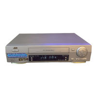
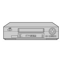
JVC HR-J271MS Instructions Manual (46 pages)
JVC Video Cassette Recorder Instruction Manual
Brand:
JVC
| Category:
VCR
| Size: 0.95 MB
Table of Contents
1
Table of Contents
2
Safety First
2
Safety Precautions
3
Installing Your New Recorder
3
Basic Connections
4
Initial Settings
4
Video Channel Set
6
Auto Set Up
6
Select Language
8
On-Screen Displays
9
Select Language
10
Clock Set
11
Playback
11
Basic Playback
12
Playback Features
13
Manual Tracking
13
Instant Review
13
Repeat Playback
14
Index Search
14
Skip Search
15
Next Function Memory
15
Picture Control
15
Tape Position Indicator
16
Recording
17
Recording Features
18
Picture System
19
Start Recording
20
Timer Recording
20
Express Timer Programming
24
Auto Sp Lp Timer
24
Auto Timer
25
Automatic Satellite Programme Recording
26
Special Features
26
Remote Control Functions
30
Colour System
30
Editing
30
Edit to or From Another Video Recorder
31
Edit From a Camcorder
32
Information On Multi-System Compatibility
33
Pal Ntsc
33
Tape-To-Tape Editing
34
Tuner Set
34
Auto Channel Set
35
Manual Channel Set
36
Delete a Channel
38
Troubleshooting
40
Other Problems
41
Questions and Answers
42
Index
43
Display Panel
45
Specifications
Advertisement
Share and save
Advertisement
Related Products
JVC HR-J278EU
JVC HR-J270EK
JVC HR-J270EU
JVC HR-J270MS
JVC HR-J277MS
JVC HR-J270
JVC HR-J272EU
JVC HR-J280EU
JVC HR-J291EA
JVC HR-J289EU
JVC Categories
Car Receiver
Camcorder
TV
VCR
Stereo System
More JVC Manuals
Login
Sign In
OR
Sign in with Facebook
Sign in with Google
Upload manual
Upload from disk
Upload from URL