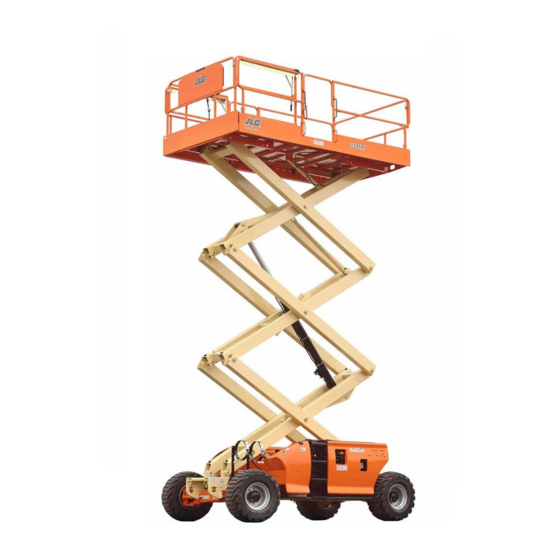
Sign In
Upload
Manuals
Brands
JLG Manuals
Lifting Systems
4394RT
JLG 4394RT Manuals
Manuals and User Guides for JLG 4394RT. We have
4
JLG 4394RT manuals available for free PDF download: Service And Maintenance Manual, Service Maintenance Manual, Operation And Safety Manual, Quick Start Manual
JLG 4394RT Service And Maintenance Manual (240 pages)
Brand:
JLG
| Category:
Lifting Systems
| Size: 22 MB
Table of Contents
Table of Contents
5
Subject - Section, Paragraph
15
Specifications
15
Capacities
15
Engines
15
Tires
16
Machine Dimensions
16
Pressure Settings
16
Serial Number Locations
16
Sensors
17
Cylinder Specifications
17
1.10 Major Component Weights
17
1.11 Critical Stability Weights
17
1.12 Lubrication Specifications
18
1.13 Maintenance Specifications
19
Fuel Tank
19
Engine Operating Temperature Specifications - Deutz
20
Engine Operating Temperature Specifications - GM
21
Drive Hub
22
Hydraulic Oil
22
Oil Change W/Filter - Deutz - D 2011 L03
23
Engine Oil Change W/Filter - Deutz D2.9 L4 - T4F
23
Oil Change W/Filter - GM - Dual Fuel
23
Engine Fuel Filter - Deutz
23
Engine Fuel Filter - Deutz D 2.9 L4 - T4F
24
Engine Fuel Filter (Gasoline) - GM
24
Air Filter
24
Electronic Pressure Regulator (LP Only)
24
Fuel Filter (Propane) - GM
24
Draining Oil Build up from the Propane Regulator
25
Propane Fuel Filter Replacement
26
Propane Fuel System Pressure Relief
26
1.14 Torque Charts
27
Torque Chart - Sheet 2 of 5 - (SAE Fasteners)
28
Torque Chart - Sheet 3 of 5 - (SAE Fasteners)
29
Torque Chart - Sheet 4 of 5 - (METRIC Fasteners)
30
Torque Chart - Sheet 5 of 5 - (METRIC Fasteners)
31
General
33
Machine Preparation, Inspection, and Maintenance
33
Preparation, Inspection, and Maintenance
33
Pre-Start Inspection
33
Pre-Delivery Inspection and Frequent Inspection
33
Annual Machine Inspection
33
Preventative Maintenance
33
Service and Guidelines
34
General
34
Safety and Workmanship
34
Cleanliness
34
Components Removal and Installation
34
Component Disassembly and Reassembly
35
Pressure-Fit Parts
35
Bearings
35
Gaskets
35
Bolt Usage and Torque Application
35
Hydraulic Lines and Electrical Wiring
35
Hydraulic System
35
Lubrication
35
Battery
35
Lubrication and Servicing
35
Lubrication and Information
36
Hydraulic System
36
Hydraulic Oil
36
Changing Hydraulic Oil
36
Lubrication Specifications
36
Cylinder Drift Test
37
Platform Drift
37
Cylinder Drift
37
Pins and Composite Bearing Repair Guidelines
37
Preventive Maintenance and Inspection Schedule
38
Preventive Maintenance and Safety Inspection
39
Chassis, Platform & Scissor Arms
41
Operating Characteristics
41
Leveling Jacks
41
Power Deck
41
Generator
41
Lift
41
Drive
41
Tires, Wheels & Drive Assembly
41
Tire Inflation
41
Tire Damage
41
Tire Replacement
42
Wheel Replacement
42
Wheel Installation
42
Drive Assembly
43
Drive Assembly (Bosch Rexroth )
43
Drive Assembly - (Fairfield/Sauer)
44
Drive Hub (Fairfield)
45
Roll and Leak Testing
45
Tightening and Torquing Bolts
45
Oil Information
45
Drive Hub
45
Drive Hub
46
Drive Hub Part Description
47
Drive Hub (Cross-Section)
48
Main Disassembly for Drive Hub
49
Hub-Spindle Disassembly
49
Cover Disassembly
50
Carrier Disassembly
50
Assembly of the Carrier
50
Cover Sub-Assembly
52
Hub-Spindle Sub-Assembly
53
Main Assembly
55
Cluster Gear Punch Marks
57
Tool List
60
Re-Aligning Torque Hub Input Coupling
60
Drive Motor (Sauer)
61
Description
61
Shaft Seal Replacement
61
Drive Motor Cross Section
61
Servo Piston
61
Loop Flushing Valve
62
Troubleshooting
63
Disassembly
64
31. Cylinder Kit Assembly
66
Swash Plate & Servo Piston
67
Inspection
68
Assembly
70
Swash Plate and Journal Bearing
71
Cylinder Kit Assembly
71
Shaft and Front Bearing
72
Cylinder Kit Installation
72
Servo Spring and Minimum Angle Stop
72
Valve Plate and Rear Bearing
73
25. End Cap
73
27. Shaft Seal
74
Initial Start-Up Procedures
75
Front Axle
76
Steering Assembly
76
Axle Assembly
77
Front Axle - Tow Bar Installation (if Equipped)
78
Tow Bar Installation (if Equipped)
78
Axle Lockout Cylinder
79
Leveling Jacks (if Equipped)
80
Cylinder Removal
80
Assembly Removal
81
Leveling Jacks Assembly
81
Platform
82
Deck Extension Cylinders (if Equipped)
83
Platform Control Station
84
Joystick Controller
85
Scissor Arms
86
Lift Cylinder Removal
86
Scissor Arms Removal
87
Scissor Arm Assembly Removal
87
Side Compartment Covers
88
3.10 Ground Control Station
89
Control Station Removal
89
Ground Control Station Removal
89
3.11 Fuel Tank
90
3.12 Hydraulic Tank
91
3.13 Battery
92
3.14 Dual Fuel/Lpg System
93
Changing from Gasoline to LP Gas
93
Changing from LP Gas to Gasoline
93
Using Liquid Petroleum (LP) Gas
93
3.15 Deutz Engine
94
Engine Tray
94
Deutz EMR 4
94
Generator (if Equipped)
95
Exhaust System
96
Exhaust System (Deutz Engine)
96
Air Cleaner System
97
Air Cleaner System (Deutz Engine)
97
Relays
98
Relays (Deutz Engine)
98
Pumps
99
Pump Coupling (Deutz Engine)
99
Pump Coupling
100
Engine Removal
101
Engine Removal (Deutz Engine)
101
Radiator
102
Radiator (Deutz Engine)
102
3.16 Gm Engine
103
Maintenance of the Drive Belt
103
Engine Electrical System Maintenance
103
Checking/Filling Engine Oil Level
103
Engine Oil Dip Stick
103
Changing the Engine Oil
104
Engine Tray
104
Engine Tray Swing
104
Generator
105
Generator (GM Engine)
105
Exhaust System
106
Air Cleaner System
107
Air Cleaner System (GM Engine)
107
Radiator
108
Radiator (GM Engine)
108
Fuel Components
109
Fuel Components (GM Engine)
109
Pumps
110
Pump Coupling
111
Pump Coupling (GM Engine)
111
Engine Removal
112
Engine Removal (GM Engine)
112
3.17 Gm Engine Dual Fuel System
113
Fuel Filter
113
Electric Lock off
113
Electronic Pressure Regulator Assembly
113
Low Pressure Regulator (LPR)
114
Air Fuel Mixer
114
Electronic Throttle Control (ETC)
115
Engine Control Module (ECM)
115
Heated Exhaust Gas Oxygen Sensor (HEGO)
116
Gasoline Multi Point Fuel Injection System (MPFI)
116
Gasoline Fuel Pump
116
Gasoline Pressure and Temperature Sensor Manifold
116
Fuel Filter
116
Gasoline Fuel Pressure and Temperature Manifold Assembly
116
Fuel Injector Rail
117
Fuel Injector
117
3.18 Gm Engine Fuel System Repair
117
Propane Fuel System Pressure Relief
117
Propane Fuel System Leak Test
117
Propane Fuel Filter Replacement
118
Electronic Pressure Regulator (EPR) Assembly Replacement
118
EPR Assembly
118
Temperature Manifold Absolute Pressure (TMAP) Sensor
119
Pressure Regulator Section
119
Electronic Throttle Control Replacement
120
Mixer Replacement
121
Coolant Hose Replacement
122
Vapor Hose Replacement
122
Engine Control Module Replacement
122
Heated Exhaust Gas Oxygen Sensor Replacement
122
3.19 Gm Engine Lpg Fuel System Diagnosis
123
Fuel System Description
123
Diagnostic Aids
123
LPF Fuel System Diagnosis
124
Symptom Diagnosis
126
DTC to SPN/FMI Cross Reference Chart
134
Hydraulics
137
Cylinders - Theory of Operation
137
Valves - Theory of Operation
137
Solenoid Control Valves (Bang-Bang)
137
Relief Valves
137
Crossover Relief Valves
137
Cylinder Checking Procedure
137
Cylinders Without Counterbalance Valves
137
Cylinders with Single Counterbalance Valve
138
Oscillating AXLE - Lockout Cylinder Test (if Equipped)
138
Left Side Wheel Test
138
Right Side Wheel Test
139
Cylinder Repair
139
Disassembly
139
Cylinder Barrel Support
140
Cylinder Rod Support
140
Cleaning and Inspection
141
Assembly
141
Bushing Installation
141
Rod Seal Installation
142
Piston Seal Kit Installation
143
Rod Assembly Installation
144
Drive Pump Start-Up Procedure
145
Hydraulic Component Start-Up Procedures & Recommendations
146
Hydraulic Gear Pump
147
Pump Disassembly
147
Parts Inspection
147
Pump Reassembly
148
Valves
150
Main Valve
151
Main Valve Schematic
152
Flow Divider Valve
153
Leveling Jacks Directional Valve
154
Powerdeck Valves
155
Leveling Jack Valves
156
Pressure Setting Procedures
157
4.10 Gear Pump
158
Gear Pump Priming
158
4.11 Axial Hi 45 Pump
159
Axial HI 45 Pump - Cross Section View
160
General Repair Instructions
161
Start-Up Procedure
161
Removing the Pump
162
Electric Control Module
163
Control Solenoids
163
Shaft Seal, Roller Bearing & Shaft Replacement
164
Charge Pump
164
Charge Check/Hprv
166
Charge Pressure Relief Valve
166
Pressure Limiter Valve Replacement
167
4.12 Charge Pump Filter
167
4.13 Auxiliary Pump Motor
168
4.14 Cylinder Assemblies
169
Lift Cylinder
170
Lift Cylinder Valve Cartridge Torque Values
171
Oscillating Axle Cylinder
172
Leveling Jack Cylinder
173
Leveling Jack Torques
174
Deck Extension Cylinder
175
Oscillating Axle Cylinder Bleeding Procedure
176
Jlg Control System
177
Hand Held Analyzer
177
To Connect the Hand Held Analyzer
177
Using the Analyzer
178
Changing the Access Level of the Hand Held Analyzer
178
Adjusting Parameters Using the Hand Held Analyzer
180
Machine Setup
180
Calibrations
182
Elevation Sensor Calibration
182
Joystick Calibration
183
Tilt Sensor Calibration
183
Tilt Sensor
184
5.3 Flash Codes and Descriptions
185
Machine Configuration Programming Information
195
Machine Tilt Configuration
196
Machine Model Adjustment
201
General Electrical Information & Schematics
203
6.1 General
203
6.2 Multimeter Basics
203
Grounding
203
Backprobing
203
Min/Max
203
Polarity
203
Scale
203
Voltage Measurement (DC)
204
Continuity Measurement
205
Continuity Measurement over Long Distances
206
Procedure
206
Requirements
206
Applying Silicone Dielectric Compound to Amp Connectors
207
Assembly
208
Disassembly
209
Wedge Lock
209
Service - Voltage Reading
210
6.4 Working with Deutsch Connectors
211
DT/DTP Series Assembly
211
DT/DTP Series Disassembly
211
HD30/HDP20 Series Assembly
211
HD30/HDP20 Series Disassembly
211
6.5 Switches
212
Basic Check
212
Limit Switches
212
Automatic Switches
213
Switch Wiring - Low Side, High Side
213
Electrical Components Installation
214
Schematics
216
Electrical Schematic - Dual Fuel
222
Hydraulic Schematic
230
Hydraulic Schematic (CE)
234
Advertisement
JLG 4394RT Service Maintenance Manual (228 pages)
Brand:
JLG
| Category:
Boom Lifts
| Size: 12 MB
Table of Contents
Hydraulic System Safety
3
Maintenance
3
Table of Contents
5
Section 1 - Specifications
11
Specifications
11
Capacities
11
Engines
11
Tires
12
Machine Dimensions
12
Pressure Settings
12
Serial Number Locations
12
Serial Number Location
12
Sensors
13
Cylinder Specifications
13
Major Component Weights
13
Critical Stability Weights
14
Lubrication Specifications
14
Operator Maintenance
15
Filter Lock Assembly
19
Torque Charts
20
Torque Chart (SAE Fasteners - Sheet 1 of 3)
20
Torque Chart (SAE Fasteners - Sheet 2 of 3))
20
Torque Chart (SAE Fasteners - Sheet 3 of 3)
20
Torque Chart (METRIC Fasteners - Sheet 1 of 3)
23
Torque Chart (METRIC Fasteners - Sheet 2 of 3))
23
Torque Chart (METRIC Fasteners - Sheet 3 of 3)
23
Section 2. General
27
Machine Preparation, Inspection, and Maintenance
27
Service and Guidelines
28
Lubrication and Information
30
Cylinder Drift Test
31
Pins and Composite Bearing Repair Guidelines
31
Preventive Maintenance and Inspection Schedule
32
Engine Operating Temperature Specifications - GM
36
Section 3. Chassis & Scissor Arms
37
Operating Characteristics
37
Calibrations
38
Level Sensor and Analyzer Connections
41
Tilt Sensor Removal
42
Integrated Torque/Drive Hub
44
Dual Fuel/Lpg System
66
Ford EFI Engine
67
Generator - Ford Engine
79
Generator (Ford Engine)
79
Generator (Deutz Engine)
79
Deutz EMR 2 (S/N 0200138634 to Present)
80
Generator - Duetz Engine
93
GM Engine General Maintenance
94
Generator - GM Engine
96
Generator (GM Engine)
96
GM Engine Dual Fuel System
97
EPR Assembly
98
Low Pressure Regulators
98
Air Fuel Mixer
99
Heated Exhaust Gas Oxygen Sensor (HEGO)
100
GM Engine Fuel System Repair
102
Pressure Regulator Section
103
GM Engine LPG Fuel System Diagnosis
108
Joystick Controller
112
Section 4 - Hydraulics
125
Cylinders - Theory of Operation
125
Valves - Theory of Operation
125
Component Functional Description
125
Cylinder Checking Procedure
126
Cylinder Repair
127
Drive Pump Start-Up Procedure
133
Hydraulic Component Start-Up Procedures and Recommendations
134
Hydraulic Gear Pump
135
Main Valve
138
Drive Header Valve (2WD)
140
Drive Header Valve (4WD)
140
Header Valves (4WD)
141
Directional Valve
142
Power Deck Sandwich Valve
143
Power Deck Manifold Valve
143
Hydraulic Pump
144
Cylinder Assemblies
146
Section 5. Jlg Control System
155
Hand Held Analyzer
155
Flash Codes and Descriptions
160
Section 6 - General Electrical Information & Schematics
179
General
179
Multimeter Basics
179
Applying Silicone Dielectric Compound to Amp Connectors
183
Working with Deutsch Connectors
188
Switches
190
Schematics
192
JLG 4394RT Operation And Safety Manual (104 pages)
0200239053
Brand:
JLG
| Category:
Lifting Systems
| Size: 8 MB
Table of Contents
Section - Paragraph, Subject
7
Table of Contents
7
Section 1 - Safety Precautions
11
General
11
Pre-Operation
12
Operator Training and Knowledge
12
Workplace Inspection
12
Machine Inspection
13
Operation
13
General
13
Trip and Fall Hazards
15
Electrocution Hazards
16
Tipping Hazards
17
Minimum Approach Distances (M.A.D.)
17
Beaufort Scale (for Reference Only)
18
Crushing and Collision Hazards
19
Towing, Lifting, and Hauling
21
Maintenance
21
Maintenance Hazards
21
Battery Hazards
22
Section 2. User Responsibilities, Machine Preparation and Inspection
23
2.1 Personnel Training
23
Operator Training
23
Training Supervision
23
Operator Responsibility
23
2.2 Preparation, Inspection, and
24
Maintenance
24
Inspection and Maintenance Table
25
Pre-Start Inspection
26
General
28
Function Check
30
Maximum Cutout Height
30
Tilt Cutout Settings
30
Lockout Cylinder Test
31
Dual Fuel System (if Equipped)
33
Section 3 - Machine Controls, Indicators and Operation
35
3.1 General
35
Description
35
Operating Characteristics and Limitations
36
General
36
Placards
36
Capacities
36
Stability
36
3.4 Ground Controls and Indicators
38
Emergency Stop Switch
38
Ground Control Station
39
Manual Descent Control
41
3.5 Platform Control Station
42
Platform Controls
43
Indicator Control Panel
46
Engine Operation
48
Platform/Ground Select Switch
48
Speed Switch
48
Starting Procedure
49
3.7 Dual Fuel System
50
Operating Characteristics
50
Platform Loading
50
Platform Capacities
50
Traveling (Driving)
51
Traveling Forward
51
Traveling in Reverse
51
Traveling on Grade
51
Steering
51
Leveling Jacks
53
Auto Leveling
53
Manual Level Adjustment (Trim)
54
Raising and Lowering Platform
54
Raising
54
Lowering
55
Platform Extension
55
Power Deck
55
Auxiliary Power
56
Generator
56
3.10 Tie Down/Lift Lugs
57
Tie down
57
Lifting
57
3.11 Towing
57
Parking and Stowing
57
Section 4 - Emergency Procedures
61
General
61
Emergency Towing Procedures
61
Emergency Controls and Their Locations
62
Emergency Stop Switch
62
Ground Control Station
62
Manual Descent
62
Emergency Operation
63
Use of Ground Controls
63
Operator Unable to Control Machine
63
Platform Caught Overhead
63
Righting of Tipped Machine
63
Post-Incident Inspection
63
Incident Notification
64
Section 5 - General Specifications and Operator Maintenance
65
Introduction
65
Supplemental Information
65
Operating Specifications
66
Dimensional Data
67
Capacities
67
Tires
68
Tire Specifications
68
Engines
69
Section - Paragraph, Subject
69
Deutz - D 2.9 L4 - T4F Engine Specifications
69
Critical Stability Weights
70
Lubrication
71
Hydraulic Oil
71
Specifications - Deutz - Sheet 2 of 2
73
Specifications - GM - Sheet 1 of 2
74
Specifications - GM - Sheet 2 of 2
75
Operator Maintenance
76
Safety Prop
76
Operator Maintenance Components
77
Fuel Tank
78
Drive Hub
78
Hydraulic Oil
79
Sliding Wear Pads
79
Oil Change W/Filter - Deutz
79
Oil Change W/Filter - Deutz D 2.9 L4 - T4F
80
Oil Change W/Filter - GM
80
Fuel Filter - Deutz
81
Fuel Filter - Deutz D 2.9 L4 - T4F
81
Fuel Filter (Gasoline) - GM
81
Air Filter
82
Electronic Pressure Regulator (LPG Only)
82
Fuel Filter (Propane) - GM
82
Draining Oil Build up from the Propane
83
Regulator
83
Filter Lock Assembly
85
Propane Fuel System Pressure Relief
86
Propane Fuel System Leak Test
87
Tires and Wheels
87
Tire Damage
87
Tire Replacement
88
Wheel Replacement
88
Wheel Installation
88
Propane Fuel Filter Replacement
85
Removal
85
Installation
85
Wheel Torque Chart
89
5.10 Decal Installation
90
Decal Location - Sheet 1 of 2 (ANSI)
90
Decal Location - Sheet 2 of 2 (ANSI)
91
Decal Location Legend - ANSI
92
Decal Installation - Sheet 1 of 2 (CE/AUS)
95
Decal Installation - Sheet 2 of 2 (CE/AUS)
96
Decal Legend - CE/AUS
97
Inspection and Repair Log
99
Section 6. Inspection and Repair Log
99
Advertisement
JLG 4394RT Quick Start Manual (9 pages)
Scissor Platform Control Measures
Brand:
JLG
| Category:
Lifting Systems
| Size: 0 MB
Table of Contents
Platform Control Measures
1
Work Platform Controls: Location, Accessibility, Protection
2
Duplicate Controls: Location, Accessibility, Protection and Selection
2
Overriding Emergency System
2
Control Measure
3
260MRT Diesel Engine Scissorlift
4
M/3369LE & M/4069LE Hybrid Scissor Lift
5
3369Le, M3369, 4069Le M4069
6
3394RT & 4394RT Diesel Scissor Lift
7
260MRT, 3394RT, 4394RT Auto Leveling Jacks
8
Advertisement
Related Products
JLG 400S
JLG 460SJ
JLG 400SJ
JLG 41AM
JLG 4017
JLG 4013PS
JLG 4014PS
JLG 40RTS
JLG 4108AN
JLG 400CRT
JLG Categories
Boom Lifts
Lifting Systems
Scissor Lifts
Construction Equipment
Work Light
More JLG Manuals
Login
Sign In
OR
Sign in with Facebook
Sign in with Google
Upload manual
Upload from disk
Upload from URL