Sign In
Upload
Manuals
Brands
Intel Manuals
Server
SR2612UR - Server System - 0 MB RAM
Intel SR2612UR - Server System - 0 MB RAM Manuals
Manuals and User Guides for Intel SR2612UR - Server System - 0 MB RAM. We have
2
Intel SR2612UR - Server System - 0 MB RAM manuals available for free PDF download: Service Manual, Product Specification
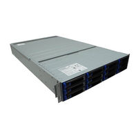
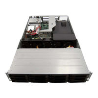
Intel SR2612UR - Server System - 0 MB RAM Service Manual (162 pages)
A Guide for Technically Qualified Assemblers of Intel Identified Subassemblies/ Products
Brand:
Intel
| Category:
Server
| Size: 7.05 MB
Table of Contents
Preface
3
Terminology Used in this Guide
3
About this Manual
3
Manual Organization
3
Safety Information
5
Important Safety Instructions
5
Wichtige Sicherheitshinweise
5
Consignes de Sécurité
5
Warnings
6
Table of Contents
7
Chapter 1: Server System Contents and References
15
Server System Contents
15
Intel Server System SR2612UR Contents
15
Disk Drive Specifications
15
Cable Specifications
15
Appliance Components and Features
16
Figure 1. Intel ® Server System SR2612UR Front View
16
About the Disk Drives and Drive Carriers
17
Figure 2. Intel ® Server System SR2612UR Rear View
17
Figure 3. Intel ® Server System SR2612UR Drive Carrier Assembly
18
Figure 4. Intel ® Server System SR2612UR Drive Slots
18
Combining SATA and SAS Disk Drives
19
Figure 5. Intel ® Server System SR2612UR Drive Configurations
19
Figure 6. Unsupported Disk Drive Combinations
20
Additional Information and Software
21
Server System References
21
Chapter 2: Server System Features
23
Figure 7. Intel Server System SR2612UR
23
Server System Feature Overview
24
Server System Components
26
Figure 8. Intel Server System SR2612UR Configuration Diagram
27
Figure 9. Intel ® Server System SR2612UR Components
28
Intel Server System SR2612UR Components
28
Intel Light-Guided Diagnostics
29
Figure 10. Intel ® Light-Guided Diagnostic Leds - Server Board
30
Figure 11. Intel Light-Guided Diagnostic Leds - Standard Control Panel
31
Server Board Components
32
Figure 12. System Power LED Back Panel
32
Figure 13. Server Board Connector and Component Locations
34
Configuration Jumpers
35
Front of Intel Server System SR2612UR
36
Peripheral Devices
36
Figure 14. Configuration Jumpers
36
Figure 15. Optional Peripherals
37
Control Panel
38
Figure 16. Rear Control Panel
38
SAS/SATA Midplanes
40
Active Midplane
40
Figure 17. Active SAS Midplane Components
40
Hot-Swap SAS/SATA Backplane
41
Figure 18. 3.5-Inch Hot-Swap SAS/SATA Backplane Components (Front View)
41
Figure 19. 3.5-Inch Hot-Swap SAS/SATA Backplane Components (Rear View)
41
RAID Support
42
Advanced Management Options
42
Intel® Remote Management Module 3
42
Rack Mount Options
42
Chapter 3: Hardware Installations and Upgrades
43
Before You Begin
43
Intel ® Server System SR2612UR Service Guide
43
Tools and Supplies Needed
43
System References
43
Preparing for Installation
43
Installing Your Intel Server System SR2612UR into a Rack (Optional)
44
Figure 20. Slider Mechanism
44
Figure 21. Securing the Front and Rear Portions of the Rail Kit
45
Figure 22. Tightening the Screws on the Rail's Slider Mechanism
45
Figure 23. Sliding the Appliance Onto the Rails
46
Installing the Disk Drives
47
Figure 24. Sliding the Disk Drive into the Drive Slot
47
Figure 25. Pushing the Lever until It Meets the Latch on Left Side of the Drive Slot
48
Removing a Disk Drive Carrier Assembly (or Drive Blank)
49
Important Safety Precautions
49
Removing a Disk Drive
49
Figure 26. Pushing the Button on the Assembly
50
Figure 27. Drive Carrier Unlocked
50
Installing the Operating System
51
Connecting Your Intel ® Server System SR2612UR to a Host Server
52
Connecting to the 1GE Iscsi LAN Data Ports
52
Connecting Additional Enclosures
52
Powering on
52
Figure 28. Establishing a Connection to the LAN Data Port
52
Installing a 2.5-Inch Internal Drive
53
Figure 29. Powering-On
53
Figure 30. Removing the Drive Sled
54
Figure 31. Installing the Boot Drives
54
DVD Installation
55
Figure 32. Connections Diagram
55
Figure 33. Removing the Four Screws and Cover Plate
56
Figure 34. Removing the Four Screws and Cover Plate
56
Replacing a Fan
57
Figure 35. Position the DVD Unit
57
Figure 36. Routing the Cable from the DVD Unit to the Server Board
57
Installing a Fan
58
Figure 37. Removing the Defective Fan
58
Midplane Board Replacement
59
Figure 38. Midplane
59
Figure 39. Disconnecting the Midplane from the Backplane
60
Memory Installation
60
Figure 40. Memory Slots on the Server Board
61
PCI Card and Battery Installation
62
Figure 41. Installing a DIMM
62
Figure 42. Lifting the PCI Cage Assembly out of the Enclosure
63
Figure 43. Routing the Cables through the Fan Assembly
64
Figure 44. Mounting an External Battery
64
Power Supply Replacement
65
Replacing the Backplane Board
65
Figure 45. Removing the Power Supply
65
Figure 46. Removing the Main Power Connector from the Backplane
66
Figure 47. Removing the Logic Cable Connector from the Backplane
66
Removing the Backplane Board
66
Figure 48. Removing the Midplane from the Enclosure
67
Figure 49. Removing the Screws that Attach the Backplane
67
Figure 50. Pulling Back the Backplane and Lifting It out of the Enclosure
67
Installing and Removing the RAID Battery Backup Unit
68
Installing the RAID Battery Backup Unit (BBU)
68
Figure 51. Locate the Battery
68
Figure 52. Remove the Standoff
69
Figure 53. Align the Battery Pack
69
Figure 54. Aligning the Battery Pack
70
Figure 55. Replace and Tighten Standoff
70
Figure 56. Route the Cable
70
Installing and Removing the Server Board
71
Removing the Server Board
71
Figure 57. Connect the Cable to PCI RAID Card
71
Figure 58. Disconnect the Power Cables
72
Figure 59. Disconnect the Fan Cables
72
Figure 60. Remove the Screws
73
Installing the Server Board
74
Figure 61. Installing the Server Board
74
Figure 62. Attach the Screws
74
Figure 63. Installing Power Cables
75
Figure 64. Install the Fan Cables
75
Replacing the Backup Battery
76
Removing and Installing the Power Distribution Module
77
Removing the Power Distribution Module
77
Figure 65. Disconnect the Power Cables
77
Figure 66. Remove the Screws
78
Figure 67. Remove Cable Chase
78
Installing Power Distribution Module
79
Figure 68. Remove the Four Screws from the PDB
79
Figure 69. Installing the Power Distribution Module
79
Figure 70. Route Cable P4
80
Figure 71. Install the Nylon Clamps
80
Figure 72. Connecting Cable P4 to Backplane
81
Figure 73. Foam Orientation
81
Figure 74. Install the Power Cables
82
Chapter 4: Server Utilities
83
Using the BIOS Setup Utility
83
Entering BIOS Setup
83
If You Cannot Access Setup
83
Setup Menus
83
Setup Menu Key Use
83
Upgrading the BIOS
85
Preparing for the Upgrade
85
Upgrading the BIOS
86
Clearing the Password
86
Restoring the BIOS Defaults
88
Appendix A: Drive Installation in the Drive Carrier
89
Introduction
89
Installing a Disk Drive in a Universal Drive Carrier
89
Figure 75. Installing a Disk Drive in a Universal Carrier
90
Installing a Blank Insert in a Universal Drive Carrier
91
Figure 76. Installing the Four Screws into the Drive Carrier
91
Figure 77. Orienting the Plastic Insert with the Drive Carrier
92
Appendix B: Intel ® Server Issue Report Form
93
Appendix C: LED Decoder
99
Appliance Status
99
LED Status Board
99
Figure 78. LED Statuses
99
Monitoring the Disk Drives
100
Figure 79. LED Board
100
Figure 80. Disk Drive Leds
100
LED Board Leds Descriptions
100
LED Status for the Disk Drive
100
Audible Alarm
101
LED Status (SAS/SATA) for the Disk Drive
101
Appendix D: Getting Help
103
Warranty Information
103
Appendix E: Regulatory and Certification Information
105
Product Regulatory Compliance
105
Product Safety Compliance
105
Product EMC Compliance - Class a Compliance
106
Product Ecology Compliance
107
Certifications / Registrations / Declarations
107
Product Regulatory Compliance Markings
109
Rack Mount Installation Guidelines
113
Power Cord Usage Guidelines
114
Electromagnetic Compatibility Notices
115
FCC Verification Statement (USA)
115
ICES-003 (Canada)
116
CE Declaration of Conformity (Europe)
116
VCCI (Japan)
116
BSMI (Taiwan)
117
KCC (Korea)
117
Regulated Specified Components
117
Appendix F: Installation/Assembly Safety Instructions
119
English
119
Deutsch
121
Français
123
Español
126
Italiano
129
System Specifications
131
Disk Drives
132
Operating Environment
133
Safety Standards
134
Environmental Protection
134
G Safety Information
137
English
137
Server Safety Information
137
Safety Warnings and Cautions
137
Intended Application Uses
138
Site Selection
138
Equipment Handling Practices
138
Power and Electrical Warnings
139
Access Warnings
139
Electrostatic Discharge (ESD)
140
Other Hazards
140
Deutsch
141
Sicherheitshinweise für den Server
141
Sicherheitshinweise und Vorsichtsmaßnahmen
141
Zielbenutzer der Anwendung
142
Standortauswahl
142
Handhabung von Geräten
143
Warnungen zu Netzspannung und Elektrizität
144
Warnhinweise für den Systemzugang
144
Elektrostatische Entladungen (ESD)
145
Andere Gefahren
146
Français
147
Consignes de Sécurité Sur Le Serveur
147
Sécurité: Avertissements Et Mises en Garde
147
Domaines D'utilisation Prévus
148
Sélection D'un Emplacement
148
Pratiques de Manipulation de L'équipement
148
Alimentation Et Avertissements en Matière D'électricité
149
Avertissements Sur L'accès Au Système
149
Décharges Électrostatiques (ESD)
150
Autres Risques
150
Español
151
Información de Seguridad del Servidor
151
Advertencias y Precauciones sobre Seguridad
151
Aplicaciones y Usos Previstos
152
Selección de la Ubicación
152
Manipulación del Equipo
153
Advertencias de Alimentación y Eléctricas
153
Advertencias el Acceso al Sistema
154
Descarga Electrostática (ESD)
155
Otros Peligros
155
Advertisement
Intel SR2612UR - Server System - 0 MB RAM Product Specification (83 pages)
Brand:
Intel
| Category:
Server
| Size: 4.1 MB
Table of Contents
Table of Contents
3
Introduction
11
Chapter Outline
11
Server Board Use Disclaimer
11
Product Overview
12
Table 1. System Feature Set
12
Processor Support
13
Table 2. Mixed Processor Configurations
14
System Overview
16
System Dimensions
16
Figure 1. Top down View
16
Table 3. System Dimensions
16
Figure 2. System Width
17
Figure 3. System Length
17
System Components
18
Figure 4. Major System Components (1 of 2)
18
Figure 5. Major System Components (2 of 2)
19
Hard Drive and Peripheral Bays
20
Figure 6. Drive Bay Overview
20
Table 4. Drive Overview
21
System Board Overview
22
Figure 7. Intel Server Board S5520UR
22
Figure 8. Intel Server Board S5520UR Components
23
Figure 9. Back Panel Feature Overview
24
Table 5. Major Board Components
24
Rack and Cabinet Mounting Options
25
Figure 10. Intel
25
Power Subsystem
26
Figure 11. Power Supply Module
26
Figure 12. Power Distribution Module
26
Mechanical Overview
27
Figure 13. Mechanical Drawing for Power Supply Module
27
Figure 14. Mechanical Drawing for Power Distribution Module
27
Handle and Retention Mechanism
28
Hot-Swap Support
28
Airflow
28
AC Power Cord Specification Requirements
28
Table 6. AC Power Cord Specifications
28
Output Connectors
29
P1 - Power Signal Connector
29
P2 - Server Board Power Connector
29
Table 7. Power Harness Cable Definitions
29
Table 8. P1 Power Signal Connector
29
P3 - Processor and Memory Power Connector
30
P4 - Backplane Power Connector
30
Table 9. P2 Main Power Connector
30
Table 10. P3 Processor/Memory Power Connector
30
Table 11. P4 Backplane Power Connector
30
P5 and P6- Auxiliary Baseboard Power Connector
31
P7, P8 and P9 - Sata/Peripheral Power Connector
31
AC Input Requirements
31
Efficiency
31
AC Input Voltage Specification
31
Table 12. P5 and P6 Auxiliary Baseboard Power Connector
31
Table 13. P7, P8, and P9 Sata/Peripheral Power
31
Table 14. Efficiency
31
AC Line Dropout/Holdup
32
AC Inrush
32
Protection Circuits
32
Over-Current Protection (OCP)
32
Table 15. AC Input Rating
32
Over-Voltage Protection (OVP)
33
Over-Temperature Protection (OTP)
33
Table 16. Over-Current Protection Limits / 240 VA Protection
33
Table 17. Over-Voltage Protection (OVP) Limits
33
DC Output Specification
34
Output Power/Currents
34
Standby Output/Standby Mode
34
3.10 Pmbus
34
Hardware
34
Table 18. Output Power and Current Ratings
34
Data Format
35
Monitoring Power/Current/Voltage
35
Thermal Management
35
Capability and Inventory Reporting
36
3.11 Power Supply Status LED
36
Table 19. LED Indicators
36
Cooling Subsystem
37
Airflow Paths
37
System Fan Module
38
Figure 15. Airflow Paths
38
Figure 16. Non-Redundant Fan Module
39
Airflow Support
40
Drive Bay Population
40
Figure 17. CPU / Memory Air Duct
40
Table 20. Non-Redundant Fan Connector Pin Assingment
40
Table 21. Non-Redundant Cooling Zones
40
Sata HDD Support
41
Figure 18. 3.5-Inch Drive Carrier with a Blank
41
System Board Interconnects
42
Active SAS Midplane
42
Figure 19. Active SAS Midplane Board
42
Hot-Swap SAS/SATA Backplane
43
Table 22. SAS Connector Pin-Out (J2)
43
Figure 20. 3.5-Inch Hot-Swap SAS/SATA Backplane (Front Side View)
44
Figure 21. 3.5-Inch Hot-Swap SAS/SATA Backplane (Back Side View)
44
Table 23. Motherboad to Backplane GPIO Pin-Out (J20)
44
Hard Drive Activity and Fault Leds
45
Table 24. Backplane Power Supply Pin-Out (J23)
45
Table 25. SAS/SATA Hard Drive Connector Pin-Outs (J1, J2
45
Table 26. Hard Drive LED Function Definitions
46
Remote RAID Controller Battery Backup Unit Mount
47
Figure 22. Remote RAID BBU Mount
47
Peripheral and Hard Drive Subsystem
48
Slimline Optical Drive Bay
49
Hard Drive Bays
49
Hot-Swap Drive Carriers
49
Figure 23. Drive Bay Overview
49
Figure 24. Slimline Optical Drive Assembly
49
Figure 25. 3.5-Inch Hard Drive Tray Assembly
50
Control Panel
51
Front LED Panel
51
Figure 26. Front LED Panel
51
Table 27. Front LED Panel Definition
51
Rear Control Panel
52
System Status LED
52
Figure 27. Rear Control Panel
52
Table 28. Rear Control Panel Functions
52
Table 29. Control Panel LED Operation
52
System Identification LED
53
PCI Riser Cards and Assembly
54
Figure 28. 2U Riser Assembly
54
Riser Card Options
55
Figure 29. 2U PCI Express* Passive Riser
55
Table 30. Riser Card Options
55
PCI Riser Card Mechanical Drawings
56
Figure 30. 2U PCI Express* Passive Riser - Primary Side
56
Figure 31. 2U PCI Express* Passive Riser - Secondary Side
57
Figure 32. 2U Butterfly PCI Express* Active Riser - Primary Side
58
Environmental Specifications
59
System Level Environmental Limits
59
Serviceability and Availability
59
Replacing the Backup Battery
59
Table 31. System Environmental Limits Summary
59
Table 32. Time Estimate for System Maintenance Procedures
59
10. Regulatory and Certification Information
61
10.1 Product Regulatory Compliance
61
Product Safety Compliance
61
Product EMC Compliance - Class a Compliance
62
Product Ecology Compliance
62
Certifications/Registrations/Declarations
63
10.2 Product Regulatory Compliance Markings
63
10.3 Rack Mount Installation Guidelines
66
10.4 Power Cord Usage Guidelines
67
10.5 Electromagnetic Compatibility Notices
67
FCC Verification Statement (USA)
67
ICES-003 (Canada)
68
Europe (CE Declaration of Conformity)
69
VCCI (Japan)
69
BSMI (Taiwan)
69
KCC (Korea)
69
10.6 Regulated Specified Components
70
Appendix A: Integration and Usage Tips
71
Appendix B: POST Code Diagnostic LED Decoder
72
Table 33. POST Progress Code LED Example
72
Table 34. Diagnostic LED POST Code Decoder
73
Appendix C: POST Code Errors
76
Table 35. POST Error Messages and Handling
76
Table 36. POST Error Beep Codes
79
Table 37. Integrated BMC Beep Codes
80
Glossary
81
Reference Documents
83
Advertisement
Related Products
Intel SR2600URLX
Intel SR2600URLXNA
Intel SR2625UR - Server System - 0 MB RAM
Intel SR2600URBRP
Intel SR2600URSATA
Intel SR2625URBRP
Intel SR2625URLX
Intel SR2520SAX - Server System - 0 MB RAM
Intel SR2100
Intel SR2400SYS - Server Platform - 0 MB RAM
Intel Categories
Motherboard
Computer Hardware
Server
Server Board
Desktop
More Intel Manuals
Login
Sign In
OR
Sign in with Facebook
Sign in with Google
Upload manual
Upload from disk
Upload from URL