
Related Manuals for Intel SR2612UR


Summary of Contents for Intel SR2612UR
- Page 1 ® Intel Server System SR2612UR Technical Product Specification Intel order number E76293-003 Revision 1.3 April 2010 Enterprise Platforms and Services Division...
- Page 2 Intel's Terms and Conditions of Sale for such products, Intel assumes no liability whatsoever, and Intel disclaims any express or implied warranty, relating to sale and/or use of Intel products including liability or warranties relating to fitness for a particular purpose, merchantability, or infringement of any patent, copyright or other intellectual property right.
-
Page 3: Table Of Contents
Intel® Server System SR2612UR TPS Table of Contents Table of Contents 1. Introduction ........................1 Chapter Outline ...................... 1 Server Board Use Disclaimer ................. 1 2. Product Overview ....................... 2 2.1.1 Processor Support ....................3 System Overview ....................6 System Dimensions ....................6 System Components .................... - Page 4 Table of Contents Intel® Server System SR2612UR TPS 3.8.2 Over-voltage Protection (OVP) ................23 3.8.3 Over-temperature Protection (OTP) ..............23 DC Output Specification ..................24 3.9.1 Output Power/Currents ..................24 3.9.2 Standby Output/Standby Mode ................24 3.10 PMBus™ ......................24 3.10.1...
- Page 5 Intel® Server System SR2612UR TPS Table of Contents PCI Riser Card Mechanical Drawings ..............46 9. Environmental Specifications ..................49 System Level Environmental Limits ..............49 Serviceability and Availability ................49 Replacing the Backup Battery ................49 10. Regulatory and Certification Information ............... 51 10.1...
- Page 6 List of Figures Intel® Server System SR2612UR TPS List of Figures Figure 1. Top Down View ......................6 Figure 2. System Width ......................7 Figure 3. System Length ......................7 Figure 4. Major System Components (1 of 2)................8 Figure 5. Major System Components (2 of 2)................9 Figure 6.
- Page 7 Intel® Server System SR2612UR TPS List of Figures Figure 33. 2U Butterfly PCI Express* Active Riser – Secondary Side ........48 Figure 34. Diagnostic LED Placement Diagram ................ 62 Revision 1.3 Intel order number E76293-003...
- Page 8 List of Tables Intel® Server System SR2612UR TPS List of Tables Table 1. System Feature Set ...................... 2 Table 2. Mixed Processor Configurations ..................4 Table 3. System Dimensions ...................... 6 Table 4. Drive Overview ......................11 Table 5. Major Board Components ................... 14 Table 6.
- Page 9 Intel® Server System SR2612UR TPS List of Tables Table 32. Time Estimate for System Maintenance Procedures ..........49 Table 33. POST Progress Code LED Example ................. 62 Table 34. Diagnostic LED POST Code Decoder ............... 63 Table 35. POST Error Messages and Handling ................ 66 Table 36.
-
Page 11: Introduction
EPS and EDS documents are not publicly available. They are only made available under NDA with Intel and must be ordered through your local Intel representative. Refer to the Reference Documents section at the end of this document for a complete list of available documents. -
Page 12: Product Overview
® ® The Intel Server System SR2612UR is a rack mount 2U server system integrated with an Intel Server Board S5520UR with features designed to support the high-density high performance computing server market. This chapter provides a high-level overview of the system features. The following chapters provide greater detail for each major system component or feature. -
Page 13: Processor Support
Processor Population Rules Note: Although the server board does support dual-processor configurations consisting of different processors that meet the following defined criteria, Intel does not perform validation testing of this configuation. For optimal system performance in dual-processor configurations, Intel recommends the installatoin of identical processors. -
Page 14: Table 2. Mixed Processor Configurations
(highest common speed) and an error is reported. Processor stepping within a common processor family can be mixed as long as it is listed in the processor specification updates published by Intel Corporation. The following table describes mixed processor conditions and recommended actions for all ®... - Page 15 Intel® Server System SR2612UR TPS Product Overview Error Severity System Action Processor frequency (speed) Major The BIOS detects the error condition and responds as follows: not identical Adjusts all processor frequencies to lowest common denominator. Continues to boot the system successfully.
-
Page 16: System Overview
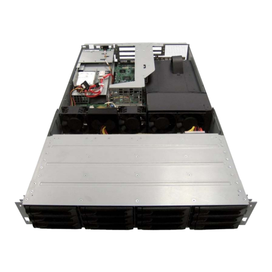
Product Overview Intel® Server System SR2612UR TPS System Overview Figure 1. Top Down View System Dimensions Table 3. System Dimensions Height 87 mm 3.43 in Width 446 mm 17.57 in Depth 781.5 mm 30.79 in Rack Mounting Surface to Rear... -
Page 17: Figure 2. System Width
Intel® Server System SR2612UR TPS Product Overview Figure 2. System Width Figure 3. System Length Revision 1.3 Intel order number E76293-003... -
Page 18: System Components
Product Overview Intel® Server System SR2612UR TPS System Components Rack Mount Ears and Handles RAID Controller Card BBU (Optional) Active SAS Midplane CPU / Memory Air Duct System Fans Assembly PCI Riser Card Assembly Power Distribution Board Figure 4. Major System Components (1 of 2) Revision 1.3... -
Page 19: Figure 5. Major System Components (2 Of 2)
Intel® Server System SR2612UR TPS Product Overview Hot-swap SAS/SATA Hard Drive Cable Retention Assembly Backplane Figure 5. Major System Components (2 of 2) Revision 1.3 Intel order number E76293-003... -
Page 20: Hard Drive And Peripheral Bays
Product Overview Intel® Server System SR2612UR TPS Hard Drive and Peripheral Bays The system is designed to support several different hard drive and peripheral configurations. The system includes a hot-swap twelve-bay backplane capable of supporting either SAS or SATA drives. You can optionally configure the internal 2.5-inch SATA hard drive bay to support two fixed 2.5-inch hard drives. -
Page 21: Table 4. Drive Overview
Intel® Server System SR2612UR TPS Product Overview Table 4. Drive Overview Product Code – SR2612UR Supported Slimline SATA Optical Drive Not Supported Slimline USB Floppy Drive Up to 12 hot-swap 3.5-inch drives plus SATA Drives two fixed 2.5-inch drives inside chassis Up to 12 hot-swap 3.5-inch drives... -
Page 22: System Board Overview
Product Overview Intel® Server System SR2612UR TPS System Board Overview ® Figure 7. Intel Server Board S5520UR The following figure shows the board layout of the server board. Each connector and major component is identified by a number or letter, and a description is given below the figure. -
Page 23: Figure 8. Intel Server Board S5520Ur Components
Intel® Server System SR2612UR TPS Product Overview ® Figure 8. Intel Server Board S5520UR Components Revision 1.3 Intel order number E76293-003... -
Page 24: Figure 9. Back Panel Feature Overview
Product Overview Intel® Server System SR2612UR TPS Table 5. Major Board Components Description Description ® ® 280-pin Intel Adaptive Riser Card Slot Fan Board Connector (Intel Server Chassis) POST Code LEDs 2x4 Power Connector ® Intel RMM3 Header Main Power Connector... -
Page 25: Rack And Cabinet Mounting Options
Intel® Server System SR2612UR TPS Product Overview POST Code Diagnostic LEDs CPU 1 DIMM Fault LEDs System Identification LED CPU 2 Fan Fault LED Status LED Memory 2 Fan Fault LED Memory 1 Fan Fault LED CPU 2 DIMM Fault LEDs... -
Page 26: Power Subsystem
Cooling Subsystem Intel® Server System SR2612UR TPS Power Subsystem The power subsystem of the system consists of an integrated Power Distribution Module (PDM), power module enclosure, and support for up to two 760-Watt power supply modules. You can configure the power subsystem to support dual modules in a 1+1 redundant power configuration. -
Page 27: Mechanical Overview
Intel® Server System SR2612UR TPS Cooling Subsystem Mechanical Overview The following figures display the Power Distribution Module and the Power Supply Module dimensions. Figure 13. Mechanical Drawing for Power Supply Module Figure 14. Mechanical Drawing for Power Distribution Module Revision 1.3... -
Page 28: Handle And Retention Mechanism
Cooling Subsystem Intel® Server System SR2612UR TPS Handle and Retention Mechanism Each power supply module includes a handle for module insertion to or removal from the module enclosure. Each module has a simple retention mechanism to hold the power module in place once it is inserted. -
Page 29: Output Connectors
Intel® Server System SR2612UR TPS Cooling Subsystem Output Connectors The power distribution board provides a cable harness providing connectors to the various system boards. The harness size, connectors, and pin outs are shown in the following tables. Listed or recognized component appliance wiring material (AVLV2), CN, rated 105°C minimum, 300 VDC minimum is used for all output wiring. -
Page 30: P3 - Processor And Memory Power Connector
Cooling Subsystem Intel® Server System SR2612UR TPS Contact: Molex Mini-Fit, HCS, Female, Crimp 44476 or equivalent Table 9. P2 Main Power Connector Signals 18 AWG Color Signal 18 AWG Colors +3.3 VDC Orange +3.3 VDC Orange +3.3 VDC Orange -12 VDC... -
Page 31: P5 And P6- Auxiliary Baseboard Power Connector
Intel® Server System SR2612UR TPS Cooling Subsystem +12V Yellow +12V Yellow +3.3V Orange Black 3.6.5 P5 and P6– Auxiliary Baseboard Power Connector Connector housing: 4-Pin Molex* 39-01-2040 or equivalent Contact: Molex* 44476-1111 or equivalent Table 12. P5 and P6 Auxiliary Baseboard Power Connector... -
Page 32: Ac Line Dropout/Holdup
Cooling Subsystem Intel® Server System SR2612UR TPS Table 15. AC Input Rating Minimu Maximu Parameter Rated Line Voltage 90 V 100 - 127 V 140 V (110) Line Voltage 180 V 200 - 240 V 264 V (220) Frequency 47 Hz... -
Page 33: Over-Voltage Protection (Ovp)
Intel® Server System SR2612UR TPS Cooling Subsystem The DC/DC converters are not damaged from repeated power cycling in this condition. The +12 V output from the power supply is divided on the PDB into four channels and each is limited to 240 VA of power. -
Page 34: Dc Output Specification
PDB addressing Address0/1 Power supply PMBus™ device ® Note: Power supply units in the Intel Server System SR2612UR use the 0/0 and 0/1 address locations. 3.10.1 Hardware The device in the power supply is compatible with both the SMBus 2.0 “high power”... -
Page 35: Data Format
Intel® Server System SR2612UR TPS Cooling Subsystem 3.10.2 Data Format The data format for current, voltage, power, temperature, and fan speed are using the PMBus Literal format. Literal data format: X = Y · 2 X = the sensor value in volts, amps, watts, degrees C, or RPM Y = mantissa. -
Page 36: Capability And Inventory Reporting
Cooling Subsystem Intel® Server System SR2612UR TPS 3.10.5 Capability and inventory reporting The follow commands are supported for discovery of the power supplies capabilities. Command Meaning CAPABILITY Defines the power supplies PEC support, bus speed, and support of SMBAlert. QUERY Defines the power supplies PEC support, bus speed, and support of SMBAlert. -
Page 37: Cooling Subsystem
To minimize acoustics, the fans operate at the lowest speed for any given condition. ® The Integrated Baseboard Management Controller (Integrated BMC) on the Intel Server Board S5520UR is used for the variable fan speed control function. The Integrated BMC monitors selective component temperatures, the ambient temperature, and each fan’s RPM to determine... -
Page 38: System Fan Module
Cooling Subsystem Intel® Server System SR2612UR TPS Figure 15. Airflow Paths System Fan Module Revision 1.3 Intel order number E76293-003... -
Page 39: Figure 16. Non-Redundant Fan Module
Intel® Server System SR2612UR TPS Cooling Subsystem A: Foam Insertion for Cable Retention Figure 16. Non-redundant Fan Module The system fan module, which includes four non-redundant 80-mm fans, is designed for ease of use and supports several management features that the Integrated Baseboard Management Controller can use. -
Page 40: Airflow Support
Cooling Subsystem Intel® Server System SR2612UR TPS Table 20. Non-redundant Fan Connector Pin Assingment Signal Name Description Return Return path to ground Power for fan Fan Tachometer signal Fan speed control signal Airflow Support Table 21. Non-redundant Cooling Zones Cooling... -
Page 41: Sata Hdd Support
Intel® Server System SR2612UR TPS Cooling Subsystem Figure 18. 3.5-inch Drive Carrier with a Blank Sata HDD Support The maximum supported temperatures when using SATA drives are affected as follows: • At 1500 m (5000 ft), the maximum ambient temperature is 25°C. -
Page 42: System Board Interconnects
System Board Interconnects Intel® Server System SR2612UR TPS System Board Interconnects System boards within the system include the midplane, bridge board, hot-swap backplane, and control panel. This chapter describes the interconnect features of each and defines the pin-outs for each connector. Later chapters describe functional details of each system board. -
Page 43: Hot-Swap Sas/Sata Backplane
Intel® Server System SR2612UR TPS System Board Interconnects Table 22. SAS Connector Pin-out (J2) Signal name Signal name HOST1_TO_IO_1+ RX0+ HOST1_TO_IO_1- RX0- HOST1_TO_IO_2+ RX1+ HOST1_TO_IO_2- RX1- Sideband connection Sideband connection Sideband connection Sideband connection HOST1_TO_IO_3+ RX2+ HOST1_TO_IO_3- RX2- HOST1_TO_IO_4+ RX3+... -
Page 44: Figure 20. 3.5-Inch Hot-Swap Sas/Sata Backplane (Front Side View)
System Board Interconnects Intel® Server System SR2612UR TPS SAS/SATA Hard Disk Drive Connectors Figure 20. 3.5-inch Hot-swap SAS/SATA Backplane (Front Side View) Backplane Power Connector Motherboard/Midplane GPIO Connector Midplane Board Connector Figure 21. 3.5-inch Hot-swap SAS/SATA Backplane (Back Side View) The following tables define the connector pin-outs for backplane board. -
Page 45: Hard Drive Activity And Fault Leds
Intel® Server System SR2612UR TPS System Board Interconnects Table 24. Backplane Power Supply Pin-out (J23) Signal Signal +3.3V +3.3V +3.3V +12V +12V +12V Fan Power (+12V) Fan Power (+12V) +12V +3.3V Table 25. SAS/SATA Hard Drive Connector Pin-outs (J1, J2, …, J12) -
Page 46: Table 26. Hard Drive Led Function Definitions
System Board Interconnects Intel® Server System SR2612UR TPS Table 26. Hard Drive LED Function Definitions Function Color Flash Pattern Indication Not Used Repeating cycle of Green for 250 Identify milliseconds/Off for 250 milliseconds Amber On constantly Fault Repeating cycle of Amber for 250... -
Page 47: Remote Raid Controller Battery Backup Unit Mount
Intel® Server System SR2612UR TPS System Board Interconnects Remote RAID Controller Battery Backup Unit Mount Figure 22. Remote RAID BBU Mount The space is provided to mount a remote Battery Backup Unit (BBU) for a hardware RAID controller car. This mount point ensures the BBU is attached correctly to chassis ground and is located in an area of enclosure that ensures correct BBU cooling. -
Page 48: Peripheral And Hard Drive Subsystem
Peripheral and Hard Drive Subsystem Intel® Server System SR2612UR TPS Peripheral and Hard Drive Subsystem You can configure the system to support several different hard drive and peripheral configurations. The peripheral/hard drive subsystem consists of a drive bay supporting a slimline optical drive, hard drives, and a flex bay;... -
Page 49: Slimline Optical Drive Bay
Once it is inserted into the system, the assembly locks into place. It is not hot-swappable. For removal, you must power down the system, remove the system’s top ® cover, and disengage the locking latch. For additional details, see the Intel Server System SR2612UR Service Guide. -
Page 50: Figure 25. 3.5-Inch Hard Drive Tray Assembly
Peripheral and Hard Drive Subsystem Intel® Server System SR2612UR TPS Hard Drive Hard Drive Connector Mounting Screw Side Rail Drive Carrier Figure 25. 3.5-inch Hard Drive Tray Assembly Revision 1.3 Intel order number E76293-003... -
Page 51: Control Panel
Control Panel ® The Intel Server System SR2612UR provides one front LED panel and one rear control panel. Both front LED panel and rear control panel provide LEDs for monitoring system status, and the rear control panel supports power button. -
Page 52: Rear Control Panel
Control Panel Intel® Server System SR2612UR TPS Color Function System Identify LED Blue The initial state of this LED is off. This blue ID LED can be illuminated by server system management software. Rear Control Panel The rear control panel houses the power switch and four status LEDs to display the system’s operating state. -
Page 53: System Identification Led
Intel® Server System SR2612UR TPS Control Panel Color State Criticality Description Correctable errors over a threshold of ten and migrating to a spare DIMM (memory sparing). This indicates that the user no longer has spare DIMMs specifying a redundancy lost condition. -
Page 54: Pci Riser Cards And Assembly
PCI Riser Cards and Assembly Intel® Server System SR2612UR TPS PCI Riser Cards and Assembly The system supports different riser card options depending on the add-in card configuration desired. The riser assembly for the system is tool-less. Standoffs on the bracket allow the riser cards to slide onto the assembly where a latching mechanism secures each riser in place. -
Page 55: Riser Card Options
Server Board S5520UR has one riser slot capable of supporting riser cards for both ® 1U and 2U system configurations. The riser slot (J4E1) implements Intel Adaptive Slot Technology. This 280-pin connector is capable of supporting riser cards that meet either the PCI-X or PCI Express* technology specifications. -
Page 56: Pci Riser Card Mechanical Drawings
PCI Riser Cards and Assembly Intel® Server System SR2612UR TPS PCI Riser Card Mechanical Drawings Figure 30. 2U PCI Express* Passive Riser – Primary Side Revision 1.3 Intel order number E76293-003... -
Page 57: Figure 31. 2U Pci Express* Passive Riser - Secondary Side
Intel® Server System SR2612UR TPS PCI Riser Cards and Assembly Figure 31. 2U PCI Express* Passive Riser – Secondary Side Revision 1.3 Intel order number E76293-003... -
Page 58: Figure 32. 2U Butterfly Pci Express* Active Riser - Primary Side
PCI Riser Cards and Assembly Intel® Server System SR2612UR TPS Figure 32. 2U Butterfly PCI Express* Active Riser – Primary Side Figure 33. 2U Butterfly PCI Express* Active Riser – Secondary Side Revision 1.3 Intel order number E76293-003... -
Page 59: Environmental Specifications
Non-palletized free fall in height 24 inches (≧40 lbs to < 80 lbs) Vibration, unpackaged 5 Hz to 500 Hz, 2.20 g RMS random ® +/-15 KV except I/O port +/- 8 KV per Intel Environmental test specification System Cooling 2550 BTU/hour... - Page 60 Environmental Specifications Intel® Server System SR2612UR TPS WARNING Danger of explosion if batter y is incor r ectly r eplaced. Replace only with the same or equivalent type r ecommended by the equipment manufactur er . Discar d used batter ies accor ding to manufactur er ’s instr uctions.
-
Page 61: 10. Regulatory And Certification Information
EMC compliance testing. For more information please contact your local Intel Representative. This is an FCC Class A device. Integration of it into a Class B chassis does not result in a Class B device. -
Page 62: Product Emc Compliance - Class A Compliance
10.1.3 Product Ecology Compliance Intel has a system in place to restrict the use of banned substances in accordance with world wide regulatory requirements. A Material Declaration Data Sheet is available for Intel products. For more reference on material restrictions and compliance you can view Intel’s Environmental Product Content Specification at http://supplier.intel.com/ehs/environmental.htm. -
Page 63: Certifications/Registrations/Declarations
Packaging & Product Recycling Marks 10.2 Product Regulatory Compliance Markings This Intel Server Chassis product if provided with the following regulatory and safety markings. In the event there is no room for a marking(s) on the chassis, the information is provided here in this document. - Page 64 Regulatory and Certification Information Intel® Server System SR2612UR TPS Regulatory Compliance Country Marking IRAM Mark Argentina Ctick Mark Australia / NZ N232 Country of Origin Mark Made in China FCC Marking (Class A) This device complies with Part 15 of the FCC Rules. Operation of...
- Page 65 Intel® Server System SR2612UR TPS Regulatory and Certification Information Regulatory Compliance Country Marking Waste of Electronic and Europe Electrical Equipment Recycling Mark China Restriction of China Hazardous Substance Environmental Friendly Use Period Mark China Recycling Mark China Recycling Marks International Perchlorate Material –...
-
Page 66: 10.3 Rack Mount Installation Guidelines
Regulatory and Certification Information Intel® Server System SR2612UR TPS Regulatory Compliance Country Marking Safety Standard icon for Power button 10.3 Rack Mount Installation Guidelines Anchor the equipment rack: The equipment rack must be anchored to an unmovable support to prevent it from falling over when one or more servers are extended in front of the rack on slides. -
Page 67: 10.4 Power Cord Usage Guidelines
Intel® Server System SR2612UR TPS Regulatory and Certification Information be labeled as controlling power to the server. The circuit breaker of a centralized DC power system may be used as a disconnect device when easily accessible and should be rated no more than 10 amps. -
Page 68: Ices-003 (Canada)
Regulatory and Certification Information Intel® Server System SR2612UR TPS Intel Corporation 5200 N.E. Elam Young Parkway Hillsboro, OR 97124-6497 1-800-628-8686 This equipment has been tested and found to comply with the limits for a Class A digital device, pursuant to Part 15 of the FCC Rules. These limits are designed to provide reasonable protection against harmful interference in a residential installation. -
Page 69: Europe (Ce Declaration Of Conformity)
English translation of the notice above: 1. Type of Equipment (Model Name): On Certification and Product 2. Certification No.: On KCC certificate. Obtain certificate from local Intel representative 3. Name of Certification Recipient: Intel Corporation 4. Date of Manufacturer: Refer to date code on product Revision 1.3... -
Page 70: 10.6 Regulated Specified Components
Updated product information for configurations can be found on the Intel Server Builder Web site at the following URL: http://channel.intel.com/go/serverbuilder If you do not have access to Intel’s Web address, please contact your local Intel representative. Server chassis (base chassis is provided with power supply and fans) — NRTL listed. -
Page 71: Appendix A: Integration And Usage Tips
Appendix A: Integration and Usage Tips Appendix A: Integration and Usage Tips ® This section provides a list of useful information unique to the Intel Server System SR2612UR ® and should be kept in mind while integrating and configuring your Intel Server Board S5520UR. -
Page 72: Appendix B: Post Code Diagnostic Led Decoder
Appendix B: POST Code Diagnostic LED Decoder Intel® Server System SR2612UR TPS Appendix B: POST Code Diagnostic LED Decoder During the system boot process, the BIOS executes a number of platform configuration processes, each of which is assigned a specific hex POST code number. As each configuration routine is started, the BIOS displays the POST code to the POST Code Diagnostic LEDs on the back edge of the server board. -
Page 73: Table 34. Diagnostic Led Post Code Decoder
Intel® Server System SR2612UR TPS Appendix B: POST Code Diagnostic LED Decoder Table 34. Diagnostic LED POST Code Decoder Diagnostic LED Decoder O = On, X=Off Checkpoint Upper Nibble Lower Nibble Description Multi-use code (This POST Code is used in different contexts) - Page 74 Appendix B: POST Code Diagnostic LED Decoder Intel® Server System SR2612UR TPS Diagnostic LED Decoder O = On, X=Off Checkpoint Upper Nibble Lower Nibble Description 0x57h Reserved for PCI bus 0x58h Resetting USB bus 0x59h Reserved for USB devices ATA/ATAPI/SATA...
- Page 75 Intel® Server System SR2612UR TPS Appendix B: POST Code Diagnostic LED Decoder Diagnostic LED Decoder O = On, X=Off Checkpoint Upper Nibble Lower Nibble Description 0xD9 Trying to boot device selection 9 0xDA Trying to boot device selection A 0xDB...
-
Page 76: Appendix C: Post Code Errors
Appendix C: POST Code Errors Intel® Server System SR2612UR TPS Appendix C: POST Code Errors Whenever possible, the BIOS outputs the current boot progress codes on the video screen. Progress codes are 32-bit quantities plus optional data. The 32-bit numbers include class, subclass, and operation information. - Page 77 Intel® Server System SR2612UR TPS Appendix C: POST Code Errors Error Code Error Message Response 8140 Processor 01 Failed FRB-3 Timer. No Pause 8141 Processor 02 Failed FRB-3 Timer. No Pause 8160 Processor 01 unable to apply BIOS update Pause...
- Page 78 Appendix C: POST Code Errors Intel® Server System SR2612UR TPS Error Code Error Message Response 856A DIMM_C3 Component encountered a Serial Presence Detection (SPD) fail error. Pause 856B DIMM_C4 Component encountered a Serial Presence Detection (SPD) fail error. Pause 856C DIMM_D1 Component encountered a Serial Presence Detection (SPD) fail error.
-
Page 79: Table 36. Post Error Beep Codes
BIOS uses these beep codes to inform users on error conditions. The beep code is followed by ® a user-visible code on the POST Progress LEDs. For complete details, refer to the Intel S5500/S5520 Server Board Family BIOS External Product Specification. -
Page 80: Table 37. Integrated Bmc Beep Codes
Appendix C: POST Code Errors Intel® Server System SR2612UR TPS Table 37. Integrated BMC Beep Codes Code Reason for Beep Associated Sensors Supported 1-5-2-1 No CPUs installed or first CPU socket is CPU Missing Sensor empty. 1-5-4-2 Power fault: DC power unexpectedly lost Power unit –... -
Page 81: Glossary
Intel® Server System SR2612UR TPS Glossary Glossary Word / Acronym Definition Australian Communication Authority ACPI Advanced Configuration and Power Interface ANSI American National Standards Institute Advanced Technology Attachment Baseboard Management Controller BIOS Basic Input/Output System CMOS Complementary Metal-oxide-semiconductor DC-to-DC Electromagnetic Compatibility... - Page 82 Glossary Intel® Server System SR2612UR TPS Word / Acronym Definition Universal Serial Bus VCCI Voluntary Control Council for Interference Voltage Regulator Down Voltage Standby Revision 1.3 Intel order number E76293-003...
-
Page 83: Reference Documents
Intel® Server System SR2612UR TPS Reference Documents Reference Documents Refer to the following documents for additional information: ® Intel Server Board S5520UR Technical Product Specification Revision 1.3 Intel order number E76293-003...
Need help?
Do you have a question about the SR2612UR and is the answer not in the manual?
Questions and answers