Sign In
Upload
Manuals
Brands
Intel Manuals
Motherboard
815
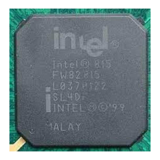
Intel 815 Manuals
Manuals and User Guides for Intel 815. We have
1
Intel 815 manual available for free PDF download: Design Manual
Intel 815 Design Manual (213 pages)
Chipset Platform For Use with Universal Socket 370
Brand:
Intel
| Category:
Computer Hardware
| Size: 2 MB
Table of Contents
Table of Contents
3
Revision History
11
Introduction
13
Terminology
14
Reference Documents
16
System Overview
16
System Features
17
Figure 1. System Block Diagram
17
Component Features
18
Graphics Memory Controller Hub (GMCH)
18
Figure 2. GMCH Block Diagram
18
Intel ® 82801AA I/O Controller Hub (ICH)
20
Firmware Hub (FWH)
20
Platform Initiatives
21
Universal Socket 370 Design
21
Accelerated Hub Architecture Interface
21
Internet Streaming SIMD Extensions
21
Agp 2.0
21
Manageability
22
Ac'97
23
Low-Pin-Count (LPC) Interface
23
2 General Design Considerations
25
Nominal Board Stackup
25
Figure 3. Board Construction Example for 60
25
3 Component Quadrant Layouts
27
Figure 4. GMCH 544-Ball BGA* CSP Quadrant Layout (Top View)
27
Figure 5. ich 241-Ball BGA* CSP Quadrant Layout (Top View)
28
Figure 6. Firmware Hub (FWH) Packages
28
4 Universal Socket 370 Design
29
Universal Socket 370 Definitions
29
Table 1. Processor Considerations for Universal Socket 370 Design
29
Table 2. GMCH Considerations for Universal Socket 370 Design
30
Table 3. ich Considerations for Universal Socket 370 Design
30
Processor Design Requirements
31
Use of Universal Socket 370 Design with Incompatible GMCH
31
Designs Using A-2 GMCH
31
Figure 7. Future 0.13 Micron Socket 370 Processor Safeguard for Universal Socket 370
31
Table 4. Clock Synthesizer Considerations for Universal Socket 370 Design
31
Figure 8. Processor Detect Mechanism at Socket/Tual5 Generation Circuit
32
Identifying the Processor at the Socket
32
Figure 9. VTT Selection Switch
33
Setting the Appropriate Processor VTT Level
33
Figure 10. Switching Pin AG1
34
Identifying the Processor at the GMCH
34
VTT Processor Pin AG1
34
Figure 11. Processor Identification Strap on GMCH
35
Table 5. Determining the Installed Processor Via Hardware Mechanisms
35
Configuring Non-VTT Processor Pins
36
Figure 12. VTTPWRGD Configuration Circuit
36
Figure 13. GTL_REF/VCMOS_REF Voltage Divider Network
37
VCMOS Reference
37
Figure 14. Resistor Divider Network for Processor PWRGOOD
38
Processor Signal PWRGOOD
38
APIC Clock Voltage Switching Requirements
39
Figure 15. Voltage Switch for APIC Clock from Clock Synthesizer to Processor
39
Figure 16. GTLREF Circuit Topology
40
GTLREF Topology and Layout
40
Power Sequencing on Wake Events
41
Gating of Intel ® CK-815 to VTTPWRGD
41
Figure 17. Gating Power to Intel ® CK-815
41
Gating of PWROK to ich
42
Figure 18. PWROK Gating Circuit for ich
42
5 System Bus Design Guidelines
43
System Bus Routing Guidelines
43
Initial Timing Analysis
43
Calculations
44
Table 6. Intel Pentium
44
General Topology and Layout Guidelines
46
Figure 19. Topology for 370-Pin Socket Designs with Single-Ended Termination (SET)
46
Table 10. Trace Width:space Guidelines
46
Table 9. Trace Guidelines for Figure 19
46
Motherboard Layout Rules for AGTL/AGTL+ Signals
47
Figure 20. AGTL/AGTL+ Trace Routing
47
Motherboard Layout Rules for Non-AGTL/AGTL+ (CMOS) Signals
49
Table 11. Routing Guidelines for Non-Agtl/Non-AGTL+ Signals
49
Additional Routing and Placement Considerations
50
Figure 21. Routing for THRMDP and THRMDN
50
THRMDP and THRMDN
50
Electrical Differences for Universal PGA370 Designs
51
THERMTRIP Circuit
51
THERMTRIP Timing
51
Figure 22. Example Implementation of THERMTRIP Circuit
51
PGA370 Socket Definition Details
52
Table 12. Processor Pin Definition Comparison
52
BSEL[1:0] Implementation Differences
56
Figure 23. BSEL[1:0] Circuit Implementation for PGA370 Designs
56
CLKREF Circuit Implementation
57
Undershoot/Overshoot Requirements
57
Figure 24. Examples for CLKREF Divider Circuit
57
Table 13. Resistor Values for CLKREF Divider (3.3V Source)
57
Processor Reset Requirements
58
Figure 25. RESET#/RESET2# Routing Guidelines
58
Table 14. RESET#/RESET2# Routing Guidelines (See Figure 25)
58
Processor PLL Filter Recommendations
59
Topology
59
Filter Specification
59
Figure 26. Filter Specification
60
Recommendation for Intel Platforms
61
Table 15. Component Recommendations - Inductor
61
Table 16. Component Recommendations - Capacitor
61
Table 17. Component Recommendation - Resistor
61
Figure 27. Example PLL Filter Using a Discrete Resistor
62
Figure 28. Example PLL Filter Using a Buried Resistor
62
Custom Solutions
63
Voltage Regulation Guidelines
63
Decoupling Guidelines for Universal PGA370 Designs
63
VCC CORE Decoupling Design
63
Figure 29. Core Reference Model
63
VTT Decoupling Design
64
VREF Decoupling Design
64
Figure 30. Capacitor Placement on the Motherboard
64
Thermal Considerations
65
Heatsink Volumetric Keepout Regions
65
Figure 31. Heatsink Volumetric Keepout Regions
66
Figure 32. Motherboard Component Keepout Regions
66
Debug Port Changes
67
Figure 33. TAP Connector Comparison
67
6 System Memory Design Guidelines
69
System Memory Routing Guidelines
69
Figure 34. System Memory Routing Guidelines
69
System Memory 2-DIMM Design Guidelines
70
System Memory 2-DIMM Connectivity
70
Figure 35. System Memory Connectivity (2 DIMM)
70
System Memory 2-DIMM Layout Guidelines
71
Figure 36. System Memory 2-DIMM Routing Topologies
71
Table 18. System Memory 2-DIMM Solution Space
71
Figure 37. System Memory Routing Example
72
System Memory 3-DIMM Design Guidelines
73
System Memory 3-DIMM Connectivity
73
Figure 38. System Memory Connectivity (3 DIMM)
73
System Memory 3-DIMM Layout Guidelines
74
Figure 39. System Memory 3-DIMM Routing Topologies
74
Table 19. System Memory 3-DIMM Solution Space
74
System Memory Decoupling Guidelines
75
Figure 40. Intel ® 815 Chipset Platform Decoupling Example
76
Compensation
77
Figure 41. Intel ® 815 Chipset Platform Decoupling Example
77
7 Agp/Display Cache Design Guidelines
79
AGP Interface
79
Graphics Performance Accelerator (GPA)
80
AGP Universal Retention Mechanism (RM)
80
Figure 42. AGP Left-Handed Retention Mechanism
81
Figure 43. AGP Left-Handed Retention Mechanism Keepout Information
81
Agp 2.0
82
AGP Interface Signal Groups
83
Table 20. AGP 2.0 Signal Groups
83
Table 21. AGP 2.0 Data/Strobe Associations
83
Standard AGP Routing Guidelines
84
1X Timing Domain Routing Guidelines
84
Flexible Motherboard Guidelines
84
AGP-Only Motherboard Guidelines
84
2X/4X Timing Domain Routing Guidelines
84
Flexible Motherboard Guidelines
85
Solutions
85
Figure 44. AGP 2X/4X Routing Example for Interfaces < 6 Inches and GPA/AGP
85
AGP-Only Motherboard Guidelines
86
AGP Routing Guideline Considerations and Summary
87
Table 22. AGP 2.0 Routing Summary
87
AGP Clock Routing
88
AGP Signal Noise Decoupling Guidelines
88
AGP Routing Ground Reference
89
Figure 45. AGP Decoupling Capacitor Placement Example
89
AGP down Routing Guidelines
90
1X AGP down Option Timing Domain Routing Guidelines
90
2X/4X AGP down Timing Domain Routing Guidelines
90
AGP Routing Guideline Considerations and Summary
91
Table 23. AGP 2.0 Routing Summary
91
AGP Clock Routing
92
AGP Signal Noise Decoupling Guidelines
92
AGP Routing Ground Reference
92
AGP 2.0 Power Delivery Guidelines
93
VDDQ Generation and TYPEDET
93
Table 24. TYPDET#/VDDQ Relationship
93
Figure 46. AGP VDDQ Generation Example Circuit
94
VREF Generation for AGP 2.0 (2X and 4X)
95
Figure 47. AGP 2.0 VREF Generation and Distribution
96
Additional AGP Design Guidelines
97
Compensation
97
AGP Pull-Ups
97
AGP Signal Voltage Tolerance List
98
Motherboard / Add-In Card Interoperability
98
Table 25. Connector/Add-In Card Interoperability
98
Table 26. Voltage/Data Rate Interoperability
98
AGP / Display Cache Shared Interface
99
GPA Card Considerations
99
AGP and GPA Mechanical Considerations
99
Display Cache Clocking
100
Designs that Do Not Use the AGP Port
100
Figure 48. Display Cache Input Clocking
100
8 Integrated Graphics Display Output
101
Analog RGB/CRT
101
Ramdac/Display Interface
101
Figure 49. Schematic of RAMDAC Video Interface
102
Reference Resistor (Rset) Calculation
103
RAMDAC Board Design Guidelines
103
Figure 50. Cross-Sectional View of a Four-Layer Board
103
Figure 51. Recommended RAMDAC Component Placement & Routing
104
RAMDAC Layout Recommendations
105
HSYNC/VSYNC Output Guidelines
105
Figure 52. Recommended RAMDAC Reference Resistor Placement and Connections
105
Digital Video out
106
DVO Interface Routing Guidelines
106
DVO I 2 C Interface Considerations
106
Leaving the DVO Port Unconnected
106
9 Hub Interface
107
Figure 53. Hub Interface Signal Routing Example
107
Data Signals
108
Strobe Signals
108
HREF Generation/Distribution
108
Compensation
109
Figure 54. Single-Hub-Interface Reference Divider Circuit
109
Figure 55. Locally Generated Hub Interface Reference Dividers
109
10 I/O Subsystem
111
IDE Interface
111
Cabling and Motherboard Requirements
111
Figure 56. IDE Minimum/Maximum Routing and Cable Lengths
112
Figure 57. Ultra ATA/66 Cable
112
Cable Detection for Ultra ATA/66
113
Host Side Cable Detection
114
Figure 58. Host-Side IDE Cable Detection
114
Device Side Cable Detection
115
Figure 59. Drive-Side IDE Cable Detection
115
Primary IDE Connector Requirements
116
Figure 60. Resistor Schematic for Primary IDE Connectors
116
Secondary IDE Connector Requirements
117
Figure 61. Resistor Schematic for Secondary IDE Connectors
117
Layout for both Host-Side and Device-Side Cable Detection
118
Figure 62. Flexible IDE Cable Detection
118
AC'97 Routing
119
Table 27. AC'97 Configuration Combinations
119
AC'97 Signal Quality Requirements
121
Motherboard Implementation
121
Using Native USB Interface
122
I/O APIC (I/O Advanced Programmable Interrupt Controller)
123
Figure 63. Recommended USB Schematic
123
Smbus
124
Pci
124
Figure 64. PCI Bus Layout Example for Four PCI Connectors
124
Lpc/Fwh
125
In-Circuit FWH Programming
125
FWH VPP Design Guidelines
125
Rtc
125
RTC Crystal
126
External Capacitors
126
Figure 65. External Circuitry of RTC Oscillator
126
RTC Layout Considerations
127
RTC External Battery Connection
127
Figure 66. Diode Circuit to Connect RTC External Battery
127
RTC External RTCRESET Circuit
128
RTC-Well Input Strap Requirements
128
Figure 67. RTCRESET External Circuit for the ich RTC
128
RTC Routing Guidelines
129
Guidelines to Minimize ESD Events
129
VBIAS and DC Voltage and Noise Measurements
129
11 Clocking
131
2-DIMM Clocking
131
Table 28. Intel CK-815 (2-DIMM) Clocks
131
Figure 68. Platform Clock Architecture (2 Dimms)
132
3-DIMM Clocking
133
Table 29. Intel CK-815 (3-DIMM) Clocks
133
Figure 69. Universal Platform Clock Architecture (3 Dimms)
134
Clock Routing Guidelines
135
Figure 70. Clock Routing Topologies
135
Table 30. Simulated Clock Routing Solution Space
136
Clock Decoupling
137
Clock Driver Frequency Strapping
137
Clock Skew Assumptions
138
Table 31. Simulated Clock Skew Assumptions
138
Intel ® CK-815 Power Gating on Wake Events
139
12 Power Delivery
141
Table 32. Power Delivery Terminology
141
Figure 71. Power Delivery Map
142
Thermal Design Power
144
Pull-Up and Pull-Down Resistor Values
144
ATX Power Supply PWRGOOD Requirements
145
Figure 72. Pull-Up Resistor Example
145
Power Management Signals
146
Power Button Implementation
147
Figure 73. G3-S0 Transition
148
V/3.3V Power Sequencing
148
Figure 74. S0-S3-S0 Transition
149
Figure 75. S0-S5-S0 Transition
150
Table 33. Power Sequencing Timing Definitions
151
Figure 76. VDDQ Power Sequencing Circuit
152
V/3.3V Power Sequencing
152
VDDQ/VCC1_85 Power Sequencing
152
Figure 77. Example 1.85V/3.3V Power Sequencing Circuit
153
Figure 78. 3.3V/V5REF Sequencing Circuitry
154
V/V5REF Sequencing
154
13 System Design Checklist
155
Design Review Checklist
155
Processor Checklist
155
GTL Checklist
155
CMOS Checklist
156
TAP Checklist for 370-Pin Socket Processors
156
Miscellaneous Checklist for 370-Pin Socket Processors
156
GMCH Checklist
158
AGP Interface 1X Mode Checklist
158
Designs that Do Not Use the AGP Port
159
Table 34. Recommendations for Unused AGP Port
159
System Memory Interface Checklist
160
Hub Interface Checklist
160
Digital Video Output Port Checklist
160
ICH Checklist
161
PCI Checklist
161
USB Checklist
162
AC '97 Checklist
162
IDE Checklist
163
Miscellaneous ich Checklist
163
LPC Checklist
165
System Checklist
166
FWH Checklist
166
Clock Synthesizer Checklist
167
LAN Checklist
168
Power Delivery Checklist
168
Power
169
Figure 79. V5REF Circuitry
169
14 Third-Party Vendor Information
171
Appendix A: Customer Reference Board (CRB)
173
Block Diagram
175
Memory Interface
180
Agp Connector
182
System Memory
183
Pci Connector
189
Ide Connectors
191
Parallel Port
193
Vga Connector
198
Audio Connectors
201
Advertisement
Advertisement
Related Products
Intel 845GL
Intel 845GV
Intel 865
Intel 815TM5
Intel 815TM
Intel 845G
Intel 815EG
Intel Celeron 847
Intel 82563EB
Intel 82564EB
Intel Categories
Motherboard
Computer Hardware
Server
Desktop
Server Board
More Intel Manuals
Login
Sign In
OR
Sign in with Facebook
Sign in with Google
Upload manual
Upload from disk
Upload from URL