Sign In
Upload
Manuals
Brands
IBM Manuals
Server
Power System E950 9040-MR9
IBM Power System E950 9040-MR9 Manuals
Manuals and User Guides for IBM Power System E950 9040-MR9. We have
2
IBM Power System E950 9040-MR9 manuals available for free PDF download: Manual, Installing Instruction
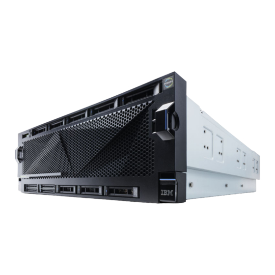
IBM Power System E950 9040-MR9 Manual (296 pages)
Temple's Zeppelin procedures for install, remove, replace
Brand:
IBM
| Category:
Server
| Size: 11 MB
Table of Contents
Table of Contents
3
Control Panel
5
Removing or Replacing the Control Panel
5
Preparing the System
5
Removing the Control Panel
7
Replacing the Control Panel
8
Preparing the System for Operation
9
Removing or Replacing the Control Panel Display
10
Preparing the System
10
Removing the Control Panel Display
12
Replacing the Control Panel Display
13
Preparing the System for Operation
14
Fans
15
Removing and Replacing a Fan
15
Preparing the System to Remove and Replace a Fan
15
Removing a Fan
20
Replacing a Fan
21
Preparing the System for Operation
22
Power Supplies
25
Removing and Replacing a Power Supply
25
Preparing the System to Remove and Replace a Power Supply
25
Removing a Power Supply
30
Replacing a Power Supply
31
Preparing the System for Operation
32
Front USB Cable
35
Removing and Replacing the Front USB Cable
35
Preparing the System to Remove and Replace a Front USB Cable
35
Removing the Front USB Cable
46
Replacing the Front USB Cable
47
Preparing the System for Operation
48
Rear USB Cable
57
Removing and Replacing the Rear USB Cable
57
Preparing the System to Remove and Replace a Rear USB Cable
57
Removing the Rear USB Cable
63
Replacing the Rear USB Cable
66
Preparing the System for Operation
69
Time-Of-Day Battery
73
Removing and Replacing the Time-Of-Day Battery
73
Preparing to Remove and Replace the Time-Of-Day Battery
73
Removing the Time-Of-Day Battery
74
Replacing the Time-Of-Day Battery
77
Preparing the System for Operation
78
SAS Cables
83
Removing and Replacing the Externally-Secured SAS Cables
83
Preparing the System to Remove and Replace the SAS Cables
83
Removing the SAS Cables
88
Replacing the SAS Cables
105
Preparing the System for Operation
120
Removing Internally-Secured SAS Cables and Replacing with Externally-Secured SAS Cables
121
Memory Modules and Memory Risers
189
Memory Modules
189
Installing a Memory Modules
189
Removing and Replacing Memory Modules in the System
198
Plugging Rules for Memory Modules in the System
211
Permanently Removing Memory Modules from the System
211
Memory Riser
220
Installing a Memory Riser
220
Removing and Replacing Memory Riser in the System
228
Permanently Removing a Memory Riser from the System
238
Service Processor Card Assembly
247
Removing and Replacing the Service Processor Card Assembly
247
Preparing the System to Remove and Replace the Service Processor Card Assembly
247
Removing the Service Processor Card Assembly
250
Replacing the Service Processor Card Assembly
251
Preparing the System for Operation
254
System Processor Modules
257
Removing and Replacing the System Processor Module
257
Preparing the System to Remove and Replace a System Processor Module
257
Removing the System Processor Module
264
Replacing the System Processor Module
271
Preparing the System for Operation after Removing and Replacing a System Processor Module
281
Common Things
285
Placing a 9040-MR9 System into the Service Position
285
Placing a 9040-MR9 System into the Operating Position
286
Removing the Service Access Cover from a 9040-MR9 System
287
Installing the Service Access Cover on the 9040-MR9 System
288
Disconnecting the Power Cords from the 9040-MR9 System
289
Connecting the Power Cords to the 9040-MR9 System
292
Removing the Front Cover from a 9040-MR9 System
292
Installing the Front Cover on a 9040-MR9 System
293
Advertisement
IBM Power System E950 9040-MR9 Installing Instruction (77 pages)
Brand:
IBM
| Category:
Server
| Size: 2 MB
Table of Contents
Table of Contents
3
Safety Notices
5
German Safety Information
5
Laser Safety Information
5
World Trade Safety Information
5
Installing a Rack-Mounted Server
15
Prerequisite for Installing the IBM Power System E950 (9040-MR9)
15
Completing Inventory for Your Server
16
Attaching the Lift Handles to the Chassis
16
Screws Needed for Rack Installation
16
Installing the Server into a Rack
17
Installing the Lift Handles
17
About this Task
18
Rack with 4 EIA Rack Units (4U)
18
Attaching the Slide Rails at the Front of the Rack
19
Attaching the Slide Rails at the Rear of the Rack
20
Removing Components from the System Chassis
20
Rear View
20
Removing the Power Supplies
21
Before You Begin
21
Removing the Pcie Adapters from the System Chassis
22
Optional: Removing the Front Cover
22
Removing the Front Cover
23
Removing the System Fans
23
Optional: Removing the Memory Risers
24
Removing the Front Fan
24
Removing the Service Access Cover
25
Installing the Cable-Management Bracket
26
Removing a Memory Riser
26
Attaching the Cable Management Bracket to the Rack
27
Installing the System into the Rack
28
Installing the Chassis Onto the Mounting Hardware
28
Pulling the Blue Rail Latch
29
Right System-To-Rail Locking Clip
29
Installing the Clip Onto the Rail
30
Replacing Components into the System Chassis
31
Releasing the Blue Latch
31
Inserting a Memory Riser
33
Installing the Service Access Cover
34
Replacing the System Fans
34
Replacing the Front Cover
35
Replacing the Pcie Adapters in the System Chassis
36
Replacing a Power Supply in the System
36
Optional: Connecting the SAS Cables to the Server
37
Plugging the SAS Cables for the Base Configuration
37
Plugging the SAS Cables for the Split Configuration
38
Cabling the Server and Setting up a Console
39
Determining Which Console to Use
39
Plugging the SAS Cables for an Expanded Function Disk Drive Backplane
39
Cabling the Server with an ASCII Terminal
40
Cabling the Server to the HMC
41
Default Settings for the Diagnostic Programs
41
Directly Attaching the HMC to the Managed System
42
Cabling the Server with Keyboard, Video, and Mouse
43
Cabling the Server and Connecting Expansion Units
43
Completing the Server Setup
44
Cabling for Power Source Redundancy: AC Feed #1
44
Cabling for Power Source Redundancy: AC Feed #2
44
Completing the Server Setup Without Using an HMC
46
Preparing to Set up Your Preinstalled Server
47
Completing Inventory for Your Preinstalled Server
48
Removing the Shipping Bracket
49
Optional: Connecting the SAS Cables to the Server
49
Installing the System Fans
52
Removing the Front Bezel
53
Installing a Front Fan
54
Installing the Power Supplies and Cabling the System
55
Replacing the Front Bezel
55
Installing a Power Supply in the System
56
Plugging in the Power Cords and Securing the Cables with Fasteners
57
Cabling the Server and Setting up a Console
57
Routing Cables through the Cable-Management Bracket and Connecting Expansion Units
61
Completing the Server Setup
61
Notices
65
Accessibility Features for IBM Power Systems Servers
66
Privacy Policy Considerations
67
Trademarks
67
Electronic Emission Notices
67
Class a Notices
67
Class B Notices
71
Terms and Conditions
73
Advertisement
Related Products
IBM Power System System E950
IBM eServer xSeries 300
IBM eServer 380 xSeries
IBM eServer xSeries
IBM Eserver pSeries 670
IBM eServer OpenPower 720
IBM Eserver xSeries 455
IBM Eserver pSeries
IBM e Server iSeries 810
IBM eServer iSeries 825
IBM Categories
Server
Desktop
Storage
Laptop
Monitor
More IBM Manuals
Login
Sign In
OR
Sign in with Facebook
Sign in with Google
Upload manual
Upload from disk
Upload from URL