Sign In
Upload
Manuals
Brands
HTC Manuals
Grinder
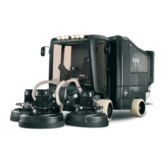
2500 iX
HTC 2500 iX Manuals
Manuals and User Guides for HTC 2500 iX. We have
2
HTC 2500 iX manuals available for free PDF download: Instructions Manual, Manual
HTC 2500 iX Instructions Manual (408 pages)
Brand:
HTC
| Category:
Grinder
| Size: 23 MB
Table of Contents
Start-Up Procedure
2
Maintenance Schedule
3
Trademarks
8
Travel and Transport on Public Roads
8
Table of Contents
9
Warranty
13
The Manual
14
Safety
15
Vibration and Noise
16
Machine Name Plate
16
On Delivery
16
Example of Machine Name Plate
17
Unpacking the Machine
18
CE Marking
18
Declaration of Conformity
19
Introduction to the HTC 2500 IX
20
Technical Specification for the HTC 2500 IX
20
The Technology and Its Benefits
21
Safety Instructions
22
Operating the Machine on a Sloping Surface
22
Machine Description - Front View
23
Description of Machine Components - Front
24
Machine Description - Rear View
25
Description of Machine Components - Rear
26
Presentation
27
Cab - Location of Controls
27
Presentation
28
Cab - Function of Controls
28
Presentation
29
System Location - Left-Hand Side
29
System Description
30
Presentation
31
System Location - Right-Hand Side
31
Presentation
32
System Description
32
Presentation
33
System Description - Interface Touch-Screen
33
Presentation
34
System Description - Interface Touch-Screen - Service
34
Presentation
35
System Description - Canopen Components' Status
35
Presentation
36
System Description - Interface Touch-Screen
36
Operation
37
Before Starting the Engine
37
Operation
38
Starting the Engine
38
Operation
39
Operation
40
Operating the Machine
40
Operation
41
Driving the Machine
41
Operation
42
Operation
43
Grinding Heads
43
Operation
44
Grinding
44
Operation
45
Folding up Grinding Head for Tool Replacement
45
Operation
46
Tool Replacement
46
Operation
47
Mist Cooler System
47
Grinding Pressure
47
Presentation
48
Suction System
48
Schematic Diagram
49
Suction System
49
Operation
51
Stopping the Engine
51
Operation
52
After Stopping the Engine
52
Care and Maintenance
53
Cleaning the Machine
53
Refuelling the Diesel Engine
53
Control Cabinet - AS1
60
Control Cabinet - AS2
62
Control Cabinet - AS3
63
Control Cabinet - AS4
64
Appendix 1 - Additions to Manual for HTC 2500
65
Appendix 2 - Maintenance Intervals for HTC 2500
67
Lifting System
76
Air System
77
Water System
79
Driving System
80
Power System
81
Engine System
82
Control System
83
Safety Instructions
84
Cabin Environment
89
Starting the Machine
91
Stopping the Machine
106
Important Safety Information
126
Foreword
128
Literature Information
128
Safety Section
129
Safety Messages
129
General Hazard Information
130
Fluid Penetration
131
Burn Prevention
131
Fire Prevention and Explosion Prevention
132
Fire Extinguisher
133
Crushing Prevention and Cutting Prevention
134
Mounting and Dismounting
134
Before Starting Engine
134
Engine Starting
135
Engine Stopping
135
Electrical System
135
Grounding Practices
136
Product Information Section
137
Model Views
137
Engine Description
140
Engine Specifications
140
Engine Cooling and Lubrication
142
Product Identification Information
143
Operation Section
148
Lifting and Storage
148
Engine Lifting
148
Engine Storage
148
Lubrication System
148
Cooling System
149
Induction System
149
Exhaust System
149
General Items
150
Gauges and Indicators
151
Engine Starting
152
Starting the Engine
153
Cold Weather Starting
153
After Starting Engine
154
Engine Operation
155
Engine Warm-Up
155
Engine Stopping
156
After Stopping Engine
156
Stopping the Engine
156
Emergency Stopping
156
Cold Weather Operation
157
Engine Block Heaters
158
Idling the Engine
158
Fuel Tanks
160
Fuel Filters
160
Maintenance Section
161
Refill Capacities
161
Fluid Recommendations
162
Engine Oil
163
Fuel Specifications
166
Fuel Recommendations
166
Cooling System Specifications
169
Coolant Recommendations
170
Maintenance Interval Schedule
175
Alternator - Inspect
177
Battery - Replace
178
Battery Electrolyte Level
178
Engine Oil Level Check
188
Engine Oil and Filter - Change
189
Drain the Engine Oil
189
Engine Valve Lash - Inspect/Adjust
191
Fuel System - Prime
193
Spin-On Filter
196
Walk-Around Inspection
201
Water Pump - Inspect
202
Warranty Section
203
Warranty Information
203
Index
204
Product Information
207
Dealer Information
207
Scope of Supply
210
Product Description
210
Operation
210
Installation
211
Cleaning and Maintenance
212
Product References
214
Introduction
227
Safety
228
General
228
Emergency Stop Button
228
Personal Protective Equipment
228
General Hazard Information
229
Pressurized Air and Water
229
Containing Fluid Spillage
229
Lines, Tubes and Hoses
229
Disposal of Waste
230
Fire and Explosion
230
Fire Extinguisher
230
Exhaust Gases
231
Mechanical
231
Chemical
231
Coolant
231
Oils
231
Batteries
231
Noise
232
Electrical
232
HAZARD LABEL LEGEND - (6.8 - 275 Kva Range)
234
HAZARD LABEL LEGEND - (350 - 2500 Kva Range)
235
General Description
236
Typical Rating Plate
236
INSTALLATION, HANDLING and Storage
239
General
239
Outdoor Installation
240
Positioning of Walk-In Containers
241
Concrete Plinth
241
Approved Lifting Methods for ISO Walk - in Containers
244
Approved Lifting Methods for Non - ISO Walk - in Containers
244
Foundations and Vibration Isolation
245
Foundation
245
Vibration Isolation
245
Storage
246
Engine Storage
246
Alternator Storage
246
Battery Storage
246
CONTROL System Description and Trouble SHOOTING
247
Control System Description
247
1002T and LCP1002 (Quickstart)
247
Control Panel Instrumentation
247
General Information1002T / LCP1002 Control Systems
249
Pre-Start Checks
249
Normal Startup / Shutdown - Key Start Panel (1002T / LCP1002 )
250
Control System Fault Finding / Trouble Shooting Guide 1002T / LCP1002
251
Powerwizard 1.0 & 2.0 (Quickstart)
252
General Information
252
Powerwizard Control Module Description
252
Pre-Start Checks (Applicable to All Control Systems)
253
Basic Operation
254
Fault / Alarm Reset Process
255
User Interface Overview
255
Alarm Log and Resetting
257
Security
258
Real Time Clock Programming (Powerwizard 2.0)
258
Fuel Priming - Engines with Electric Fuel Lift Pump
259
Additional Features Available
259
Trouble Shooting Guide for Powerwizard
259
Powerwizard 1.1, 1.1+ & 2.1 (Quickstart)
260
General Information
260
Powerwizard Control Module Description
260
Pre-Start Checks (Applicable to All Control Systems)
261
Basic Operation
263
Fault / Alarm Reset Process
264
User Interface Overview
264
Alarm Log and Resetting
266
Security
267
Real Time Clock Programming (Powerwizard 2.1)
268
Fuel Transfer (Powerwizard 2.1)
268
Additional Features Available
268
Trouble Shooting Guide for Powerwizard
269
Dcp-20
270
General Information
270
DCP Control Module Description
270
Pre-Start Checks (Applicable to All Control Systems)
271
Basic Operation
272
Fault / Alarm Reset Process - DCP-10
273
Fault / Alarm Reset Process - DCP-20
273
User Interface Overview
273
Control System Options and Upgrades
276
Battery Trickle / Switch-Mode Chargers
276
Heaters
276
Electric Fuel Transfer Pumps
276
Meters / Gauges
277
Speed / Voltage Control
277
Alarm Signalling
277
Automatic Preheat Control
277
Remote Annunciator Panels
277
Operation
278
Priming Procedure for 1100 Series
278
Products Fitted with the Racor Pre-Filter / Water Separator (Option)
279
Troubleshooting
280
Starting with Jump Start Cables
280
LOAD Transfer Panels
282
Engine Interface Module Description (Where Fitted)
283
Output Circuit Breaker Description
283
Electronic Engine FAULT Detection FLASH Codes
284
Maintenance
285
Battery Removal and Fitting
285
Preventative Maintenance
286
Alternator Preventative Maintenance
286
Engine Preventative Maintenance
286
Decommissioning, Dismantling and Disposal
286
Operator Interface AMF and MRS
290
Display Screens Structure
292
AMF Main Screens Structure
292
MRS Main Screens Structure
293
Alarms, Events and History
294
Events
295
Warnings
296
Shutdowns
296
ECU Messages
297
Start and Stop Engine
299
AMF in MANUAL Mode
299
MRS in MANUAL Mode
299
AMF in AUTO Mode
299
MRS in AUTO Mode
299
Technical Characteristics
312
Electrical Characteristics
312
Installation
313
Mechanical Checks
314
Terminal Connection Diagrams
314
Servicing & Maintenance
317
Regular Maintenance
317
Fault Detection
317
Mechanical Defects
318
Electrical Faults
318
Dismantling, Reassembly
320
Spare Parts
324
First Maintenance Parts
324
Technical Support Service
324
Exploded Views, Parts List
325
Product Designation
335
EU-Guidelines
335
Main Filter
338
Tekniska Data
341
Technical Performance
341
Warranty
351
Problem Solving
352
HTC 24C / 55C Manual (SV)
353
HTC 24C / 55C Teknisk Data / Technical Performance
353
HTC 24C Exploded View
354
HTC 24C Spare Part List
355
HTC 55C Assemble Instruction
356
HTC 55C Exploded View
358
HTC Spare Part List
359
Information
362
Generell Information
362
Säkerhets- Och Informationsmärkning
362
Säkerhetsinformation
363
Generell Säkerhetsinformation, Transport
363
Checklista
364
Växelenhetens Konstruktion
366
Mekanisk Installation
372
Förvaring
372
Förarbeten
373
Uppsättning Av Växelenheten
374
Växelenheter Med Solid Axel
375
Montage Och Demontage Av Klämkoppling
377
Montage Och Demontage Av Skyddskåpa
379
Montage Av Momentstag
383
Idrifttagande
384
Oljenivå I Växelenheten VID Leverans
384
Temperaturmätning
384
Kontroll Av Växelenheten
385
Drifttagning Av Växelenheter/Växelmotorer I EX
385
Inspektion Och Underhållsintervaller
386
Driftstörningar
387
Driftstörningar På Växelenheten
387
Inspection and Maintenance
387
Lubricants
388
Angle Parallel Shaft Gear Unit
394
Helical Worm Gear Unit
395
Oil Level Control of Gear Units with Oil Level Plug at
396
Declaration of Conformity
397
Gear Units of Category I M2
398
Gear Units of Category II 2G and
400
Gear Units of Category II 3G and II 3D
402
WATT DRIVE Partner
403
Advertisement
HTC 2500 iX Manual (391 pages)
Brand:
HTC
| Category:
Grinder
| Size: 11 MB
Table of Contents
Trademarks
10
Travel and Transport on Public Roads
10
Table of Contents
11
Warranty
15
The Manual
16
Safety
17
Vibration and Noise
18
Machine Name Plate
18
On Delivery
18
Example of Machine Name Plate
19
Unpacking the Machine
20
CE Marking
20
Declaration of Conformity
21
Introduction to the HTC 2500 IX
22
Technical Specification for the HTC 2500 IX
22
The Technology and Its Benefits
23
Safety Instructions
24
Operating the Machine on a Sloping Surface
24
Machine Description - Front View
25
Description of Machine Components - Front
26
Machine Description - Rear View
27
Description of Machine Components - Rear
28
Presentation
29
Cab - Location of Controls
29
Presentation
30
Cab - Function of Controls
30
Presentation
31
System Location - Left-Hand Side
31
System Description
32
Presentation
33
System Location - Right-Hand Side
33
Presentation
34
System Description
34
Presentation
35
System Description - Interface Touch-Screen
35
Presentation
36
System Description - Interface Touch-Screen - Service
36
Presentation
37
System Description - Canopen Components' Status
37
Presentation
38
System Description - Interface Touch-Screen
38
Operation
39
Before Starting the Engine
39
Operation
40
Starting the Engine
40
Operation
41
Operation
42
Operating the Machine
42
Operation
43
Driving the Machine
43
Operation
44
Operation
45
Grinding Heads
45
Operation
46
Grinding
46
Operation
47
Folding up Grinding Head for Tool Replacement
47
Operation
48
Tool Replacement
48
Operation
49
Mist Cooler System
49
Grinding Pressure
49
Presentation
50
Suction System
50
Schematic Diagram
51
Suction System
51
Operation
53
Stopping the Engine
53
Operation
54
After Stopping the Engine
54
Care and Maintenance
55
Cleaning the Machine
55
Refuelling the Diesel Engine
55
Control Cabinet - AS1
62
Control Cabinet - AS2
64
Control Cabinet - AS3
65
Control Cabinet - AS4
66
Appendix 1 - Additions to Manual for HTC 2500 IX
67
Appendix 2 - Maintenance Intervals for HTC 2500 IX
69
Foreword
130
Safety Section
131
Safety Messages
131
General Hazard Information
132
Burn Prevention
133
Fire Prevention and Explosion Prevention
134
Crushing Prevention and Cutting Prevention
136
Mounting and Dismounting
136
Before Starting Engine
136
Engine Starting
137
Engine Stopping
137
Electrical System
137
Product Information Section
139
Model Views
139
Product Identification Information
145
Operation Section
150
Lifting and Storage
150
Gauges and Indicators
153
Engine Starting
154
Engine Operation
157
Engine Stopping
158
Cold Weather Operation
159
Maintenance Section
163
Refill Capacities
163
Maintenance Interval Schedule
177
Warranty Section
205
Warranty Information
205
HTC 24C / 55C Manual (SV)
335
HTC 24C / 55C Teknisk Data / Technical Performance
335
HTC 24C Exploded View
336
HTC 24C Spare Part List
337
HTC 55C Assemble Instruction
338
HTC 55C Exploded View
340
HTC Spare Part List
341
Information
345
Generell Information
345
Säkerhets- Och Informationsmärkning
345
Säkerhetsinformation
346
Generell Säkerhetsinformation, Transport
346
Checklista
347
Växelenhetens Konstruktion
349
Mekanisk Installation
355
Förvaring
355
Förarbeten
356
Uppsättning Av Växelenheten
357
Växelenheter Med Solid Axel
358
Montage Och Demontage Av Klämkoppling
360
Montage Och Demontage Av Skyddskåpa
362
Montage Av Momentstag
366
Idrifttagande
367
Oljenivå I Växelenheten VID Leverans
367
Temperaturmätning
367
Kontroll Av Växelenheten
368
Drifttagning Av Växelenheter/Växelmotorer I EX
368
Inspektion Och Underhållsintervaller
369
Driftstörningar
370
Driftstörningar På Växelenheten
370
Inspection and Maintenance Work on Gear U
370
Malfunctions
370
Malfunctions on the Gear Unit
370
Table of Tightening Torques
371
Lubricants
371
Angle Parallel Shaft Gear Unit
377
Helical Worm Gear Unit
378
Oil Level Control of Gear Units with Oil Level Plug at
379
Declaration of Conformity
380
Gear Units of Category I M2
381
Gear Units of Category II 2G and
383
Gear Units of Category II 3G and II 3D
385
WATT DRIVE Partner
386
Advertisement
Related Products
HTC 270 EG
HTC Hero Android 2.1
HTC DROID INCREDIBLE 2 by Verizon
HTC Tilt 2 NM8RHOD00
HTC Tilt 2 RHOD00
HTC 2125
HTC Desire 210
HTC 2 RHOD500
HTC 2PS6400
HTC 2PPN
HTC Categories
Cell Phone
Virtual Reality Headsets
Floor Machine
PDA
Measuring Instruments
More HTC Manuals
Login
Sign In
OR
Sign in with Facebook
Sign in with Google
Upload manual
Upload from disk
Upload from URL