Sign In
Upload
Manuals
Brands
H3C Manuals
Firewall
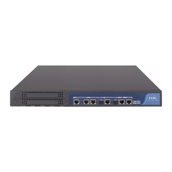
H3C SECPATH F1000-S
H3C H3C SECPATH F1000-S Firewall Manuals
Manuals and User Guides for H3C H3C SECPATH F1000-S Firewall. We have
1
H3C H3C SECPATH F1000-S Firewall manual available for free PDF download: Installation Manual
H3C H3C SECPATH F1000-S Installation Manual (78 pages)
Brand:
H3C
| Category:
Firewall
| Size: 2 MB
Table of Contents
About this Manual
3
Table of Contents
6
Chapter 1 Product Overview
12
Brief Introduction
12
Figure 1-1 Front Panel of the H3C Secpath F1000-S Firewall
13
Figure 1-2 Rear Panel of the H3C Secpath F1000-S Firewall
13
Hardware Features
13
Appearance
13
System Description
13
Table 1-1 Technical Specifications of the H3C Secpath F1000-S Firewall
13
Table 1-2 Leds on the Front Panel of the H3C Secpath F1000-S Firewall
14
Attributes of the Fixed Interfaces
15
Leds
14
Table 1-4 Attributes of the aux Port
15
Table 1-3 Attributes of the Console Port
15
Table 1-6 Attributes of the GE Optical Interfaces
16
Table 1-5 Attributes of the GE Electrical Interfaces
16
Mims
17
Chapter 2 Preparation for Installation
19
Site Requirements
19
Cleanliness
19
Temperature/Humidity
19
Table 2-1 Temperature/Humidity Requirements in the Equipment Room
19
Electromagnetic Environment
20
ESD Prevention
20
Table 2-3 Limit of Harmful Gases in the Equipment Room
20
Table 2-2 Dust Limit in the Equipment Room
20
Lightning Protection
21
Mounting Rack
21
Safety Precautions
21
Tools, Meters, and Devices
22
Unpacking and Inspection
22
Chapter 3 Hardware Installation
23
Figure 3-1 Installation Procedure
23
Table 3-1 Dimensions of the H3C Secpath F1000-S Firewall
24
Figure 3-3 Grounding Screw on the Firewall
26
Connecting the Ethernet Interface
27
Connecting the Grounding Wires
25
Installing an MIM
25
Connecting to the Console Terminal
26
Mounting the Device
24
Freestanding the Device
24
Rack-Mounting the Device
24
Figure 3-4 Console Cable Assembly
27
Figure 3-5 Ethernet Cable Assembly
28
Figure 3-6 Power Socket on a Dual AC Power Supply Firewall
30
Verifying Installation
31
Connecting a PSU
30
Chapter 4 Booting and Configuration
32
Booting
32
Setting up a Configuration Environment
32
Figure 4-1 Local Configuration through the Console Port
32
Figure 4-2 Create a New Connection
33
Figure 4-3 Select Serial Interface
33
Figure 4-4 Set Port Parameters
34
Figure 4-5 Select Emulation Type
35
Powering up the Firewall
35
Booting Process
36
Configuration Fundamentals
37
Basic Configuration Procedure
37
Command Line Interface
38
Chapter 5 Software Maintenance
39
Introduction
39
Boot Menu
39
Upgrading the Application and Boot ROM Programs Using Xmodem
40
Figure 5-1 Send File Dialog Box
41
Figure 5-3 Set up an Environment for Local Uploading/Downloading
46
Figure 5-4 Set up an Environment for Remote Uploading/Downloading
47
Modifying Boot ROM Password
50
Resetting a Lost Password
51
Figure 5-2 Sending File Interface
42
Backing up and Restoring the Extended Segment of the Boot ROM Program
43
Upgrading an Application Program Using TFTP
44
Uploading/Downloading a Program/File Using FTP
46
Chapter 6 Hardware Maintenance
52
Opening the Chassis Cover
52
Preparing Tools
52
Figure 6-1 Open the Chassis
53
Replacing a DDR SDRAM
53
Figure 6-2 DDR SDRAM Maintenance Flow
54
Table 6-1 Memory Specifications
55
Figure 6-4 Remove a DDR SDRAM
56
Closing the Chassis Cover
57
Installing a DDR SDRAM
57
Replacing an MIM
58
Removing a DDR SDRAM
56
Locating the DDR Sdrams on the Mainboard
55
Figure 6-3 Position of the DDR Sdrams, Flash, and Boot ROM on the Mainboard
56
Figure 6-5 Close the Chassis Cover
58
Chapter 7 Troubleshooting
59
Troubleshooting the Power System
59
Troubleshooting the Configuration System
59
Troubleshooting the Software Upgrade
60
Chapter 8 Multifunctional Interface Modules
62
Installing and Removing an MIM
62
MIM Options
62
Figure 8-2 Install the MIM II
63
Figure 8-1 Install the MIM I
63
1FE/2FE/4FE Module
64
Introduction
64
Appearance
64
Troubleshooting an MIM
64
Figure 8-3 1FE Module
65
Figure 8-5 4FE Module
65
Table 8-3 Straight-Through Cable Pinout
68
Figure 8-11 1GBE Module
70
Figure 8-12 2GBE Module
70
Table 8-5 Interface Attributes of the 1GBE/2GBE Module
70
Figure 8-13 1GBE Module Panel
71
Figure 8-14 2GBE Module Panel
71
Interface Cable
71
Panel and Interface Leds
71
Table 8-6 Leds on the 1GBE/2GBE Module
71
Figure 8-15 Ethernet Cable
72
Figure 8-16 Category-5 Twisted-Pair Cable
72
1GEF/2GEF Module
73
Appearance
73
Figure 8-17 1GEF Module
73
Figure 8-18 2GEF Module
73
Introduction
73
Interface Attributes
74
Panel and Interface Leds
74
Table 8-7 Interface Attributes of the 1GEF/2GEF Module
74
Figure 8-19 1GEF Module Panel
75
Figure 8-20 2GEF Module Panel
75
Interface Fiber Cable
75
Table 8-8 Leds on the 1GEF/2GEF Module
75
Appearance
76
Connecting the Interface Fiber Cable
76
Introduction
76
SSL Module
76
Figure 8-22 SSL Module Panel
77
Module Attributes
77
Panel and Module Leds
77
Table 8-10 Leds on the SSL Module
77
Table 8-9 SSL Module Attributes
77
Troubleshooting SSL Module
78
Figure 8-4 2FE Module
65
Connecting the Interface Cable
72
Figure 8-6 1FE Module Panel
66
Figure 8-8 4FE Module Panel
66
Interface Attributes
66
Panel and Interface Leds
66
Figure 8-7 2FE Module Panel
66
Table 8-2 Leds on the 1FE/2FE Module
67
Table 8-4 Crossover Cable Pinout
68
Connecting the Interface Cable
69
1GBE/2GBE Module
70
Appearance
70
Interface Attributes
70
Introduction
70
Table 8-1 Interface Attributes of the 1FE, 2FE and 4FE Modules
66
Figure 8-9 Ethernet Cable
67
Interface Cable
67
Figure 8-21 SSL Module
77
Advertisement
Advertisement
Related Products
H3C H3C SECPATH F1000-A
H3C SecPath F1000-E
H3C SecPath F1000-AK155
H3C SecPath F1000-AK185
H3C SecPath F1000-AI-5 Series
H3C SecPath F1000-AI-25
H3C F1000-AI-50
H3C F1000-AI-70
H3C F1000-AI-80
H3C F1000-AI-90
H3C Categories
Switch
Network Router
Wireless Access Point
Control Unit
Server
More H3C Manuals
Login
Sign In
OR
Sign in with Facebook
Sign in with Google
Upload manual
Upload from disk
Upload from URL