Sign In
Upload
Manuals
Brands
Fujitsu Manuals
Air Conditioner
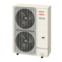
AIRSTAGE J-III AG A004GCAH Series
Fujitsu AIRSTAGE J-III AG A004GCAH Series Manuals
Manuals and User Guides for Fujitsu AIRSTAGE J-III AG A004GCAH Series. We have
1
Fujitsu AIRSTAGE J-III AG A004GCAH Series manual available for free PDF download: Design & Technical Manual
Fujitsu AIRSTAGE J-III AG A004GCAH Series Design & Technical Manual (1124 pages)
Brand:
Fujitsu
| Category:
Air Conditioner
| Size: 63.37 MB
Table of Contents
Table of Contents
4
Model Line up
5
Outdoor Unit
5
Indoor Unit
6
Controller
10
Adaptor / Convertor / Maintenance Tool
12
Branch Kit
14
Header
14
Ev Kit
15
Cassette Grille
15
OTHERS (Optional Parts)
16
Model Selection Procedure
23
Model Line up
24
Outdoor Unit
24
Indoor Unit
25
Optional Parts
27
Model Selection and Capacity Calculation
29
Selection Procedure of Indoor Unit and Outdoor Unit
29
Method of Capacity Calculation
31
The Example of Calculation
32
Capacity Table Cooling (Outdoor Unit)
36
Capacity Table Heating (Outdoor Unit)
45
Capacity Compensation Coefficient
51
Capacity Table Cooling (Indoor Unit)
52
Compact Cassette Type
52
Circular Flow Cassette Type
55
Cassette Type
59
Mini Duct Type
62
Slim Duct/Slim Concealed Floor Type
65
Medium Static Pressure Duct Type
67
High Static Pressure Duct Type
68
Large Airflow Duct Type
70
COMPACT FLOOR TYPE (EEV External Model)
71
Floor / Ceiling Type
75
Ceiling Type
76
WALL MOUNTED TYPE (EEV External Model)
77
Capacity Table Heating (Indoor Unit)
85
Compact Cassette Type
85
Circular Flow Cassette Type
87
Cassette Type
90
Mini Duct Type
93
Slim Duct/Slim Concealed Floor Type
95
Medium Static Pressure Duct Type
97
High Static Pressure Duct Type
98
Large Airflow Duct Type
100
COMPACT FLOOR TYPE (EEV External Model)
101
Floor / Ceiling Type
105
Ceiling Type
106
WALL MOUNTED TYPE (EEV External Model)
107
Specifications
117
Dimensions
118
Installation Space
121
Single Outdoor Unit Installation
121
Multiple Outdoor Unit Installation
122
Outdoor Units Installation in Multi Row
122
Duct Installation
124
Refrigerant Circuit
126
Wiring Diagram
128
Operation Range
130
Noise Level Curve
131
Electric Characteristics
134
Safety Devices
135
Low Static Pressure Duct / Concealed Floor Type
169
Mini Duct Type
169
Mini Duct Type
185
Slim Duct / Slim Concealed Floor Type
189
Medium Static Pressure Duct Type
194
High Static Pressure Duct Type
196
Large Airflow Duct Type
201
Compact Floor Type
211
COMPACT FLOOR TYPE (EEV External Model)
211
Wall Mounted Type
213
WALL MOUNTED TYPE (EEV External Model)
213
Line up of Controllers
469
Control System Design
472
System Configuration Examples
473
Features of Control System
481
Wiring System
482
Control Equipment Design Limitation
483
Control Units
485
System Controller
486
Model: Uty-Apgxz1
486
(Option: UTY-PEGXZ1, UTY-PPGXP2)
486
MODEL: UTY-APGX (Option: UTY-PEGX)
491
System Controller Lite
495
Model: Uty-Algxz1
495
(Option: UTY-PLGXA2, UTY-PLGXR2, UTY-PLGXE2, UTY-PLGXP2, UTY-PLGXX2)
495
Touch Panel Controller
506
Central Remote Controller
521
Group Remote Controller
529
WIRED REMOTE CONTROLLER (Touch Panel)
533
Wired Remote Controller
538
Wired Remote Controller
542
SIMPLE REMOTE CONTROLLER (with Operation Mode)
547
Model: Uty-Rsr
547
Model: Uty-Rsk
552
SIMPLE REMOTE CONTROLLER (Without Operation Mode)
556
Model: Uty-Rhr
556
Model: Uty-Rhk
561
Wireless Remote Controller
565
IR RECEIVER UNIT (for ALL DUCT TYPE)
569
IR RECEIVER UNIT (for CASSETTE TYPE)
572
IR RECEIVER UNIT (for CIRCULAR FLOW CASSETTE TYPE)
574
HUMAN SENSOR KIT (for CIRCULAR FLOW CASSETTE TYPE)
576
Remote Sensor Unit
578
Group Control Method
580
Comparison Table of Controllers
582
Adaptor / Convertor Units
584
Network Convertor
585
Model: Uty-Vtgx
587
Model: Uty-Vtgxv
590
Network Convertor
593
Knx Convertor for Vrf
598
Knx Convertor for Indoor Unit
607
Modbus ® Convertor for Indoor Unit
622
Network Convertor for LON WORKS
629
Bacnet ® GATEWAY (HARDWARE)
642
Gateway (Software)
647
Model: Uty-Abgxz1
647
Model: Uty-Abgx
652
Signal Amplifier
657
Wireless Lan Adapter
661
External Switch Controller
664
Model: Uty-Terx
664
Model: Uty-Tekx
671
Service & Web Monitoring Tool
675
Service Tool
675
Model: Uty-Asgxz1
675
Model: Uty-Asgx
680
Web Monitoring Tool
684
Model: Uty-Amgxz1
684
Model: Uty-Amgx
687
System Design
692
Refrigerant System
692
Example of Refrigerant System
693
Vrf Network System
695
Mounting Position
701
Piping Design
703
Important Items When Using Refrigerant R410A
703
Piping Limitation
705
Pipe Size
707
Selection of Pipe Heat Insulating Material
711
Additional Charge Calculation
712
Example of Piping Design
713
Piping Connection
717
Caution of Piping
717
Piping to Outdoor Unit
719
Separation Tube
722
Header
725
Ev Kit
728
Wiring Design
732
Electrical Wiring
732
Power Supply Cable Wiring
734
Transmission Line
746
Controller Cable Wiring
746
Drain Connection
748
Outdoor Unit
748
Indoor Unit
749
Standard Accessories
763
Outdoor Unit
763
Indoor Unit
764
Function Setting
782
System Setting
782
System Type Setting
782
Address Setting
784
Manual Address Setting Method
788
Address Setting by Remote Controller
798
Wireless Remote Controller
798
Wired Remote Controller (Uty-Rnk*)
805
Simple Remote Controller (Uty-Rsr*, Uty-Rhr*)
810
Simple Remote Controller (Uty-Rsk*, Uty-Rhk*)
816
Wired Remote Controller (Uty-Rnr*Z*, Uty-Rnr*)
821
Wired Remote Controller (Uty-Rlr*)
826
Automatic Address Setting
831
Signal Amplifier Automatic Address Setting
833
Indoor Unit Automatic Address Setting
835
Rb Unit Automatic Address Setting
837
Example Flow
839
Terminal Resistor Setting
842
Indoor Unit Connection Check
843
Function Setting
846
Outdoor Unit
846
VR-II Series
849
Series
854
Series
859
J-IIIL, J-III, J-II Series
863
J-IIS Series
867
INDOOR UNIT (Setting by Switch)
872
INDOOR UNIT (Setting by Wireless Remote Controller)
883
INDOOR UNIT (Setting by UTY-RNK*)
890
INDOOR UNIT (Setting by UTY-RSR*, UTY-RHR*)
894
INDOOR UNIT (Setting by UTY-RSK*, UTY-RHK*)
898
INDOOR UNIT (Setting by UTY-RNR*)
902
INDOOR UNIT (Setting by UTY-RLR*)
906
Function Setting
910
Function Details
910
Rb Unit
912
Wired, Simple Remote Controller
915
Group Remote Controller
917
Touch Panel Controller
919
Central Remote Controller
920
WIRED REMOTE CONTROLLER (Touch Panel)
921
Remote Controller Address Setting
921
Remote Controller Master/Slave Setting
923
Indoor Unit Address Verification
924
Wired Remote Controller (Uty-Rlr*)
925
Remote Controller Address Setting
925
Remote Controller Master/Slave Setting
927
Indoor Unit Address Verification
928
Simple Remote Controller (Uty-Rsr*, Uty-Rhr*)
929
Remote Controller Address Setting
929
Remote Controller Master/Slave Setting
931
Indoor Unit Address Verification
932
Network Convertor
933
Models: Uty-Vtgx / Uty-Vtgxv
933
Model: Uty-Vggxz1
934
Signal Amplifier
935
Knx Convertor for Vrf
937
Knx Convertor for Indoor Unit
939
Modbus ® Convertor for Vrf
940
Modbus ® Convertor for Indoor Unit
942
Duct Static Pressure Setting
944
Administrative Indoor Unit Setting
946
Setting Method
947
Energy Saving Setting (System Controller)
950
Electricity Charge Apportionment Setting
957
Controller, Touch Panel Controller)
957
External Input & Output
977
Outdoor Unit
977
External Input
980
External Output
982
Optional Parts
983
Indoor Unit
985
External Input
985
External Output
998
Optional Parts
1000
Rb Unit
1002
External Input
1002
Optional Parts
1005
Touch Panel Controller
1006
External Input
1006
External Output
1010
Optional Parts
1010
Central Remote Controller
1011
External Input
1011
External Output
1014
Optional Parts
1014
Refrigerant Leakage Caution
1018
Introduction
1018
Checking Concentration Limit
1019
Installation Precautions
1021
Indoor Unit Installation Precautions
1021
Outdoor Unit Installation Precautions
1024
Compatibility of Vrf System
1025
About Connection between Series
1030
Piping Connection
1030
Wiring Connection
1031
Separation Tube
1036
Separation Tube for 2 Pipes
1039
Separation Tube for 3 Pipes
1043
Outdoor Unit Branch Kit
1049
Header
1052
Header for 2 Pipes
1053
Header for 3 Pipes
1057
Ev Kit
1065
Rb Unit
1066
Specifications
1066
Dimensions
1067
Installation
1069
Refrigerant Circuit
1071
Wiring Diagrams
1073
Electric Characteristics
1076
Safety Devices
1077
Controller
1078
Adaptor / Convertor / Maintenance
1080
Cassette Grille
1083
Others
1084
Parts List
1084
Indoor Unit
1084
Others
1092
Optional Parts Installation
1099
Drain Pump Unit
1099
Fresh Air Intake Kit (Model : Utz-Vxaa)
1106
Fresh Air Intake Kit (Model: Utz-Vxra, Utz-Vxga)
1113
Auto Louver Grille Kit
1120
Advertisement
Advertisement
Related Products
Fujitsu Airstage AS A004GTEH Series
Fujitsu AS A004GCGH Series
Fujitsu AirStage AG A004GCEH Series
Fujitsu AS A004HCAH Series
Fujitsu AIRSTAGE J-III AG A007GCAH Series
Fujitsu AIRSTAGE J-III AG A009GCAH Series
Fujitsu Airstage AS A009GTEH Series
Fujitsu AS A007GCGH Series
Fujitsu AS A009GCGH Series
Fujitsu AS A005HCAH Series
Fujitsu Categories
Air Conditioner
Laptop
Server
Scanner
Storage
More Fujitsu Manuals
Login
Sign In
OR
Sign in with Facebook
Sign in with Google
Upload manual
Upload from disk
Upload from URL