Sign In
Upload
Manuals
Brands
Emerson Manuals
Measuring Instruments
Rosemount 1056
Emerson Rosemount 1056 Manuals
Manuals and User Guides for Emerson Rosemount 1056. We have
4
Emerson Rosemount 1056 manuals available for free PDF download: Instruction Manual, Manual, Quick Start Manual
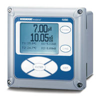
Emerson Rosemount 1056 Instruction Manual (127 pages)
Dual-Input Intelligent Analyzer
Brand:
Emerson
| Category:
Measuring Instruments
| Size: 6 MB
Table of Contents
Warning: Risk of Electrical Shock
2
Quick Start Guide Chart
4
Model 1056 Menu Tree
5
Table of Contents
7
1 Description and Specifications
9
Features and Applications
9
Diagnostics
10
Display
10
Current Outputs
10
Single or Dual Turbidity
10
Specifications - General
11
Contacting Conductivity (Code -20 and -30)
12
Toroidal Conductivity (Code -21 and -31)
13
Ph/Orp/Ise (Code -22 and -32)
14
Flow (Code -23 and -33)
15
4-20Ma Current Input (Code -23 and -33)
15
Chlorine (Code -24 and -34)
16
Free and Total Chlorine
16
Monochloramine
16
Ph-Independent Free Chlorine
16
Dissolved Oxygen (Code -25 and -35)
17
Dissolved Ozone (Code -26 and -36)
17
Performance Specifications
17
Recommended Sensors
17
Turbidity (Code 27 and 37)
18
2 Installation
19
Unpacking and Inspection
19
General Information
19
Panel Mounting Dimensions
20
Wall/Surface Mount
21
Pipe Mount
21
CSA Non Incendive Field Wiring Installation
22
FM Non Incendive Field Wiring Installation
23
CSA Nonincendive Class I, Division 2 Certified Product for Selected Configurations
24
CSA Nonincendive Class I, Division 2
25
FM Nonincendive Class I, Division 2
26
3 Wiring
29
Preparing Conduit Openings
29
Removable Connectors and Signal Input Boards
29
Digital Communication Boards
29
General
29
Preparing Sensor Cable
29
Power, Output, Alarms and Sensor Connections
29
Preparing Sensor Cable
30
Power, Output, and Sensor Connections
30
Power Wiring
30
Current Output Wiring
31
Alarm Relay Wiring
31
Sensor Wiring to Signal Boards
31
Signal Board Wiring
32
Contacting Conductivity Signal Board and Sensor Cable Leads View
32
Toroidal Conductivity Signal Board and Sensor Cable Leads View
32
Ph/Orp/Ise Signal Board and Sensor Cable Leads View
33
Amperometric Signal (Chlorine, Oxygen, Ozone) Board and Sensor Cable Leads View
33
Turbidity Signal Board with Plug-In Sensor Connection View
34
Flow/Current Input Signal Board and Sensor Cable Leads View
34
Power Wiring for the 1056 115/230VAC Power Supply (-01 Order Code) View
35
Power Wiring for the 1056 85-265 VAC Power Supply (-03 Ordering Code) View
35
Output Wiring for Model 1056 Main PCB
36
Power Wiring for Model 1056 24VDC Power Supply (-02 Ordering Code)
36
4 Display and Operation
37
User Interface
37
Instrument Keypad
37
Function Keys
37
Main Display
37
Menu System
37
Main Display
38
Process Measurements
38
Displayable Secondary Values
38
Selection Keys
38
Menu System
39
Fault and Warning Banner
39
Formatting the Main Display
39
Formatting the Main Display - Chart
40
5 0 Programming - Basics
41
Programming the Analyzer - Basics
41
Purpose
41
Procedure
41
General
41
Changing the Startup Settings
41
Choosing Temperature Units and Automatic/Manual Temperature Compensation
42
Configuring and Ranging the Current Outputs
42
Definitions
42
Procedure: Configure Outputs
43
Procedure: Assigning Measurements the Low and High Current Outputs
43
Procedure: Ranging the Current Outputs
43
Setting a Security Code
44
Security Access
45
Using Hold
45
How the Security Code Works
45
Using the Hold Function
45
Resetting Factory Default Settings
46
Programming Alarm Relays
47
Procedure – Enter Setpoints
48
Procedure – Assign Measurement
48
Procedure – Set Relay Logic
48
Procedure – Deadband, USP Safety, Normal State
48
Procedure – Interval Time
49
Procedure – on Time
49
Procedure – Recovery Time
49
Procedure – Hold While Active, Simulate, Synchronize
49
Programming Measurements - Introduction
51
Orp
51
Contacting Conductivity
51
Toroidal Conductivity
51
Turbidity
51
Flow
51
Current Input
51
Ph Measurement Programming
52
ORP Measurement Programming
53
Resolution
53
Solution Temperature Correction
53
Temperature Coefficient
53
To Configure the ORP Measurement Board
54
Contacting Conductivity Measurement Programming
55
Sensor Type
55
Cell Constant
56
Range
56
RTD Offset
56
RTD Slope, Temp Comp
56
Custom Setup, Cal Factor
57
Filter
57
Reference Temp
57
Slope
57
Sensor Model
58
Toroidal Conductivity Measurement Programming
58
Temp Comp
59
Custom Setup
60
Ref Temp
60
Chlorine Measurement Programming
61
Free Chlorine Measurement Programming
61
To Configure the Chlorine Measurement Board for Free Chlorine
61
Free Chlorine Ph Correction
62
Manual Ph Correction
62
Units
62
Total Chlorine Measurement Programming
63
Measure: Monochloramine
64
Monochloramine Measurement Programming
64
To Configure the Chlorine Measurement Board for Monochloramine
64
Ph-Independent Free Chlorine Measurement Programming
65
Measurement: Ph-Independent Free Chlorine
66
Oxygen Measurement Application
67
Oxygen Measurement Programming
67
Partial Press
68
Pressure Units
68
Salinity
68
Use Pressure
68
Ozone Measurement Programming
69
Turbidity Measurement Programming
70
Enter TSS Data
71
Bubble Rejection
72
Flow Measurement Programming
73
Current Input Programming
74
Ma Input
74
High Value
76
Low Value
76
Configuring Ph/Orp Measurements
77
LIQ-MAN-1056 April
77
Configure Contacting Measurements
78
Configure Toroidal Measurements
79
Configure Oxygen Measurements
80
Configure Chlorine Measurements
81
Configure Ozone Measurements
81
Configure Turbidity Measurement
82
Configure Flow Measurement
83
Configure Ma Current Input Measurement
83
Free Chlorine
85
Total Chlorine
85
Calibration - Introduction
85
Ph Calibration
85
ORP Calibration
85
Contacting Conductivity Calibration
85
Toroidal Conductivity Calibration
85
Chlorine Calibration
85
Monochloramine
85
Oxygen Calibration
85
Auto Calibration — Ph
86
Ph Calibration
86
Entering a Known Slope Value — Ph
87
Manual Calibration — Ph
87
Standardization — Ph
87
ORP Calibration
88
Standardization — ORP
88
Contacting Conductivity Calibration
89
Calibrating the Sensor in a Conductivity Standard (in Process CAL)
90
Entering the Cell Constant
90
Zeroing the Instrument
90
Cal Factor
91
Calibrating the Sensor to a Laboratory Instrument (Meter Cal)
91
Toroidal Conductivity Calibration
92
O Calibrate the Sensor in a Conductivity Standard (in Process Cal)
93
Calibration — Chlorine
94
Calibration — Free Chlorine
94
Monochloramine
94
Free Chlorine Calibration Routines
95
In Process Calibration
95
Zeroing the Sensor
95
Calibration — Total Chlorine
96
Calibration - Monochloramine
98
Ph-Independent Free Chlorine Measurement
100
Calibration — Oxygen
102
Oxygen Calibration Routines
103
Calibrating the Sensor against a Standard Instrument (in Process Cal)
104
Calibrating the Sensor in Air
104
Calibration — Ozone
105
Calibrating Temperature
107
Turbidity
108
Slope Calibration - Turbidity
108
Standardize Calibration - Turbidity
109
Pulse Flow
110
Grab Calibration - Turbidity
110
Calibration — K Factor
111
Calibration — Freq/Velocity and Pipe
111
Calibration — in Process Cal
112
Calibration — Totalizer Control
112
Calibrate Ph Chart
113
Calibrate ORP Chart
114
Calibrate Contacting and Toroidal Conductivity
115
Calibrate Free Chlorine, Total Chlorine, Monochloramine, and Ph-Independent Free Chlorine
116
Calibrate Oxygen
117
Calibrate Ozone
118
Calibrate Temperature
119
Calibrate Turbidity
120
Calibrate Flow
121
8 Return of Material
123
Warranty
123
EC DECLARATION of Conformity
125
Advertisement
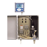
Emerson Rosemount 1056 Manual (108 pages)
Total Chlorine System with Rosemount 1056 Transmitter
Brand:
Emerson
| Category:
Measuring Instruments
| Size: 1 MB
Table of Contents
Table of Contents
5
Chapter 1 Description and Specifications
9
Features
9
Specifications
10
Ordering Information and Accessories
13
Chapter 2 Principles of Operation
17
Principles of Operation
17
Chapter 3 Installation
19
Unpacking and Inspection
19
Installation
19
General Information
19
Install the Transmitter
19
Install the Sample Conditioning Enclosure
21
Install the Sensor
24
Chapter 4 Wiring
27
Prepare Transmitter Conduit Openings
27
Provide Power to the Sample Conditioning System
27
Make Power, Alarm, Output, and Sensor Connections in the Transmitter
28
Power
28
Analog Output Wiring
29
Alarm Wiring
30
Sensor Wiring
30
Apply Power to the Transmitter and Complete Quick Start
32
Chapter 5 Startup
35
Prepare the Reagent
35
Zero the Sensor
36
Start Sample Flow
36
Begin Operation and Calibrate the Sensor
36
Chapter 6 Display and Operation
37
Display
37
Keypad
38
Programming the Transmitter - Tutorial
40
Security
42
How the Security Code Works
42
Assigning Security Codes
42
Bypassing Security Codes
42
Using Hold
43
Purpose
43
Using the Hold Function
43
Configuring the Main Display
44
Chapter 7 Programming the Transmitter
47
General
47
Default Settings
47
Configuring, Ranging, and Simulating Outputs
49
Purpose
49
Definitions
49
Procedure - Configure Outputs
50
Procedure - Ranging Outputs
51
Procedure - Simulating Outputs
52
Configuring Alarms and Assigning Setpoints
54
Purpose
54
Definitions
54
Procedure - Configuring Alarms and Assigning Setpoints
56
Procedure - Simulating Alarms
58
Procedure - Synchronizing Timers
59
Configuring the Measurement
60
Purpose
60
Definitions
60
Procedure - Configuring the Measurement
60
Configuring Temperature Related Settings
61
Purpose
61
Definitions - Chlorine
62
Procedure - Configuring Temperature Related Settings
62
Configuring Security Settings
63
Purpose
63
Procedure - Configuring Security Settings
64
Resetting the Transmitter
64
Purpose
64
Procedure - Resetting the Transmitter
65
Chapter 8 Digital Communications
67
Chapter 9 Calibration
69
Introduction
69
Calibrating Temperature
69
Purpose
69
Procedure
69
Calibrating Total Chlorine
71
Purpose
71
Procedure - Zeroing the Sensor
73
Procedure - Calibrating the Sensor
75
Calibrating Analog Outputs
77
Purpose
77
Procedure
77
Chapter 10 Maintenance
79
Transmitter
79
Total Chlorine Sensor
80
General
80
Cleaning the Membrane
80
Replacing the Membrane
80
Replacing the Electrolyte Solution and Membrane
81
Sample Conditioning System
82
Reagent
82
Sample and Reagent Tubing
83
Replacing Sample Tubing
84
Peristaltic Pump Tubing
85
Replacing the Air Pump
88
Replacing the Air Pump Diaphragm and Check Valves
90
Chapter 11 Troubleshooting
93
Overview
93
Using the Diagnostic Feature
93
Troubleshooting When a Fault Message Is Showing
94
Main Board CPU, Main Board Factory Data, and Main Board User Data Errors
94
Hardware Error
95
Sensor Board Unknown, Sensor Board HW (Hardware) or SW (Software) Mismatch, or Sensor Board Not Communicating
95
Sensor Incompatible
95
Sensor CPU Error
95
Sensor RTD Open
96
Sensor 1 Not Detected
96
Sensor Factory Data, Sensor Board User Data, and Sensor EEPROM Write Errors
96
Sensor ADC Error
96
Sensor RTD out of Range
96
Troubleshooting When a Warning Message Is Showing
97
Sensor Need Factory Cal
97
Sensor Negative Reading
97
Sensor RTD Sense Open
97
Sensor Temperature High or Low
98
Troubleshooting When no Error Message Is Showing
98
Zero Current Is too High
99
Zero Current Is Unstable
99
Sensitivity Is Low or Readings Are Low
99
Process Readings Are Erratic or Wander
101
Readings Drift
102
Readings Are too High
102
Temperature was more than 3 °C Different from Transmitter
102
Current Output Is too Low
102
Alarm Relays Don't Work
102
Simulating Inputs
103
Simulating Temperature
103
General
103
Simulating Temperature
104
Chapter 12 Return of Material
107
Return of Material
107
Emerson Rosemount 1056 Quick Start Manual (48 pages)
Intelligent Four-Wire Transmitter
Brand:
Emerson
| Category:
Transmitter
| Size: 21 MB
Table of Contents
Table of Contents
3
First Steps
5
Installation
12
Wiring
13
Navigating the Display
30
Start up the Transmitter
36
Approvals
39
Product Certifications
40
EU Declaration of Conformity
43
China Rohs Table
45
Advertisement
Emerson Rosemount 1056 Quick Start Manual (36 pages)
Four-Wire, Dual-Input Intelligent Transmitter
Brand:
Emerson
| Category:
Transmitter
| Size: 22 MB
Table of Contents
Table of Contents
3
First Steps
5
Install
9
Wire
10
Navigating the Display
23
Startup
29
EU Declaration of Conformity
32
China Rohs Table
34
Advertisement
Related Products
Emerson Rosemount 1057
Emerson Rosemount Analytical 1054B C
Emerson Rosemount 1054B
Emerson Rosemount 1054BC-01
Emerson Rosemount 1054BLC
Emerson Rosemount 1054BLC-01
Emerson Rosemount 1054BPH-01
Emerson 1056-03-24-38-AN
Emerson 1056-03-24-32-AN
Emerson FloBoss 103
Emerson Categories
Controller
Control Unit
Transmitter
Measuring Instruments
Fan
More Emerson Manuals
Login
Sign In
OR
Sign in with Facebook
Sign in with Google
Upload manual
Upload from disk
Upload from URL