Sign In
Upload
Manuals
Brands
Emerson Manuals
Analytical Instruments
Oxymitter 5000
Emerson Oxymitter 5000 Manuals
Manuals and User Guides for Emerson Oxymitter 5000. We have
2
Emerson Oxymitter 5000 manuals available for free PDF download: Instruction Manual
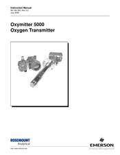
Emerson Oxymitter 5000 Instruction Manual (226 pages)
Oxygen Transmitter
Brand:
Emerson
| Category:
Analytical Instruments
| Size: 3.03 MB
Table of Contents
Table of Contents
7
Essential Instructions
11
Section I Introduction
13
SECTION I
13
Preface
14
Definitions
14
Symbols
14
Oxymitter 5000 with Fieldbus Communications
15
What You Need to Know
15
Can You Use the Quick Start Guide
18
Quick Start Guide for Oxymitter 5000 Systems
19
Quick Reference Guide Manual Calibration Instructions
20
Section 1 Description and Specifications
23
Description and Specifications
23
Component Checklist
23
System Overview
23
Scope
23
SECTION 1 Component Checklist
23
Foundation Fieldbus Technology
25
System Description
25
System Configuration
26
IMPS 4000 (Optional)
27
System Features
27
Handling the Oxymitter 5000
29
System Considerations
29
SPS 4001B (Optional)
31
IMPS 4000 (Optional)
33
SPS 4001B (Optional)
33
Mounting
33
Operation
33
Probe Options
34
Diffusion Elements
34
Specifications
37
Section 2 Installation
43
Installation
44
IM-106-350, Rev
44
Mechanical Installation
44
Probe Installation
44
Selecting Location
44
Remote Electronics Installation
52
Electrical Installation (with Integral Electronics)
53
Electrical Installation (with Remote Electronics)
56
Install Interconnecting Cable
59
Pneumatic Installation
59
IMPS 4000 Connections
61
SPS 4001B Connections
61
Verify Installation
63
Configuration of Oxymitter 5000 with Membrane Keypad
63
Mechanical Installation
63
Logic I/O
63
SECTION 3 Verify Installation
63
Terminal Block Wiring
63
Logic I/O
64
Logic I/O
66
Recommended Configuration
67
Oxymitter 5000 Configuration
70
Recommended Configuration
73
Power up
75
Operation
76
Power up
79
Navigating the Local Operator Interface
81
Start up Oxymitter 5000 Calibration
81
LOI Key Designations
82
LOI Menu Tree
82
Oxymitter 5000 Setup at the LOI
84
LOI Installation
87
Oxymitter 5000 Test Points
88
Section 7 Model 375 Handheld Communicator
89
Fieldbus Terminal Block Connections
89
Overview
89
Off-Line and On-Line Operations
90
Logic I/Oconfigurations
91
Fieldbus Menu Tree
92
FOUNDATION Fieldbus O
93
Section 8 Troubleshooting
95
Overview
95
Alarm Indications
97
General
97
Alarm Contacts
98
Identifying and Correcting Alarm Indications
99
Calibration Passes but Still Reads Incorrectly
116
Heater Not Open, but Unable to Reach 736° C Setpoint
116
Overview
119
Automatic Calibration
120
Semi-Automatic Calibration
121
Calibration with LOI
124
Oxymitter 5000 Repair
126
Replace Entire Integral Electronics (with Housing)
129
Electronic Assembly Replacement
130
Terminal Block Replacement
131
Entire Probe Replacement (Excluding Probe Head)
132
Heater Strut Replacement
133
Cell Replacement
135
Ceramic Diffusion Element Replacement
138
SECTION 10 Probe Replacement Parts
141
Section 11 Optional Accessories
147
Model 375 Handheld Communicator
147
Asset Management Solutions (AMS)
148
By-Pass Packages
148
IMPS 4000 Intelligent Multiprobe Test Gas Sequencer
149
SPS 4001B Single Probe Autocalibration Sequencer
150
O 2 Calibration Gas
151
Catalyst Regeneration
152
APPENDIX B Returning Material
183
APPENDIX C Fieldbus Parameters
185
Appendix D Analog Input (Ai) Function Block
191
APPENDIX A Safety Instructions
191
Parameter
191
Parameter
192
APPENDIX D Simulation
195
Direct
195
Alarm Detection
196
Modes
196
Status Handling
197
Advanced Features
198
Application Information
198
Application Examples
199
Pressure Transmitter Used to Measure Level in an Open Tank
200
Differential Pressure Transmitter to Measure Flow
202
Troubleshooting
203
Appendix E Pid Function Block
205
Bkcal_In
206
APPENDIX E Setpoint Selection and Limiting
210
Tracking
210
Bumpless Transfer and Setpoint Tracking
211
Output Selection and Limiting
211
PID Equation Structures
211
Reverse and Direct Action
211
Block Errors
212
Modes
212
Reset Limiting
212
Alarm Detection
213
Application Information
214
Status Handling
214
Application Examples
215
Bkcal_In
216
Feedforward Control
216
Bkcal_Out
217
Cascade Control with Master and Slave Loops
217
Cas_In
217
Cascade Control with Override
218
Troubleshooting
220
Advertisement
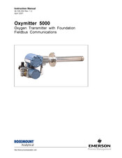
Emerson Oxymitter 5000 Instruction Manual (164 pages)
Oxygen Transmitter with Foundation Fieldbus Communications
Brand:
Emerson
| Category:
Transmitter
| Size: 2.82 MB
Table of Contents
Table of Contents
5
Definitions
9
Preface
9
Safety Instructions
11
Material Safety Data Sheet
13
Figure 1. Oxymitter 5000 Installation Options
20
Can You Use the Following Quick Start Guide
21
Figure 2. Oxymitter 5000 with SPS 4000 Wiring Diagram
23
Figure 3. Oxymitter 5000 Without SPS 4000 Wiring Diagram
23
Fast Key Sequences
25
Hart Communicator
25
Figure 1-1. Typical System Package
26
Component Checklist of Typical System (Package Contents)
27
Description and Specifications
27
System Overview
27
IB-106-350 Rev
28
Figure 1-2. Oxymitter 5000 Autocalibration System Options
29
Figure 1-3. Oxymitter 5000 FOUNDATION Fieldbus Connections
30
IMPS 4000 (Optional)
30
Figure 1-4. Typical System Installation
31
SPS 4000 (Optional)
32
Specifications
34
Table 1-1. Specifications
34
Table 1-2. Product Matrix
36
Table 1-3. Calibration Gas Bottles
37
Table 1-4. Intelligent Multiprobe Test Gas Sequencer Versions
38
Table 1-5. Single Probe Autocalibration Sequencer Coding
38
Installation
39
Mechanical Installation
39
Figure 2-1. Oxymitter 5000 Installation
40
Figure 2-2. Oxymitter 5000 Installation (with SPS 4000)
41
Figure 2-3. Oxymitter 5000 with Abrasive Shield
42
Figure 2-4. Oxymitter 5000 Adaptor Plate Installation
43
Figure 2-5. Oxymitter 5000 Mounting Flange Installation
44
Figure 2-6. Oxymitter 5000 Bracing Installation
45
Figure 2-7. Orienting the Optional Vee Deflector
45
Figure 2-8. Installation with Drip Loop and Insulation Removal
46
Electrical Installation (for Oxymitter 5000 Without SPS 4000)
47
Electrical Installation (for Oxymitter 5000 with SPS 4000)
48
Figure 2-9. Terminal Block
48
Figure 2-10. SPS 4000 Electrical Connections
50
Figure 2-11. Air Set, Plant Air Connection
51
Pneumatic Installation (for Oxymitter 5000 Without SPS 4000)
51
Figure 2-12. Oxymitter 5000 Gas Connections
52
Pneumatic Installation (for Oxymitter 5000 with SPS 4000)
52
Figure 3-1. Integral Electronics
53
General
53
Startup and Operation
53
Figure 3-2. Oxymitter 5000 Defaults
55
Logic I/O
56
Table 3-1. Logic I/O Configuration
56
Recommended Configuration
57
Table 3-2. Logic I/O Parameters
57
Figure 3-3. Startup and Normal Operation
58
Power up
58
Figure 3-4. Calibration Keys
59
IMPS 4000 Connections
59
Start up Oxymitter 5000 Calibration
59
Figure 3-5. Normal Operation
60
General
60
Calibration
63
Maintenance and Service
63
Overview
63
Figure 4-1. Oxymitter 5000 Exploded View
64
Figure 4-2. Membrane Keypad
65
Figure 4-3. Inside Right Cover
66
LED Status Indicators
68
Oxymitter 5000 Removal/ Replacement
68
Table 4-1. Diagnostic/Unit Alarms
68
Figure 4-4. Terminal Block
69
Figure 4-5. Electronic Assembly
70
Electronics Replacement
71
Figure 4-6. J8 Connector
71
Figure 4-7. Fuse Location
73
Entire Probe Replacement (Excluding Electronics)
74
Heater Strut Replacement
74
Figure 4-8. Heater Strut Assembly
75
Cell Replacement
76
Figure 4-9. Cell Replacement Kit
76
Ceramic Diffusion Element Replacement
78
SPS 4000 Maintenance and Component Replacement
79
Figure 4-11. SPS 4000 Manifold Assembly
80
Figure 4-12. Power Supply Board and Interface Board Connections
82
Figure 4-13. Calibration Gas and Reference Air Components
86
Alarm Contacts
87
Alarm Indications
87
General
87
Troubleshooting
87
Figure 1-5. SPS 4000
88
Identifying and Correcting Alarm Indications
88
Table 5-1. Diagnostic/Unit Alarm Fault Definitions
88
Figure 5-1. Fault 1, Open Thermocouple
89
Figure 5-2. Fault 2, Shorted Thermocouple
90
Figure 5-3. Fault 3, Reversed Thermocouple
91
Figure 5-4. Fault 4, A/D Comm Error
92
Figure 5-5. Fault 5, Open Heater
93
Figure 5-6. Fault 6, High High Heater Temp
94
Figure 5-7. Fault 7, High Case Temp
95
Figure 5-8. Fault 8, Low Heater Temp
96
Figure 5-9. Fault 9, High Heater Temp
97
Figure 5-10. Fault 10, High Cell MV
98
Figure 5-11. Fault 11, Bad Cell
99
Figure 5-12. Fault 12, EEPROM Corrupt
100
Figure 5-13. Fault 13, Invalid Slope
101
Figure 5-14. Fault 14, Invalid Constant
102
Figure 5-15. Fault 15, Last Calibration Failed
103
SPS 4000 Troubleshooting
104
Table 5-2. SPS 4000 Fault Finding
105
Figure 5-16. SPS 4000 Troubleshooting Flowchart (Sheet 1 of 2)
106
Optional Accessories
109
Return of Material
111
Replacement Parts
113
Table 8-1. Replacement Parts for Probe
113
Figure 8-1. Cell Replacement Kit
116
Figure 8-2. Probe Disassembly Kit
117
Table 8-2. Replacement Parts for Electronics
118
Table 8-3. Replacement Parts for SPS 4000
120
Table 8-4. Replacement Parts for Calibration Gas Bottles
120
Appendices
121
Appendix A. Fieldbus Parameter Description
121
Appendix B. Analog Input (AI) Function Block
121
Appendix C. PID Function Block
121
Index
161
Advertisement
Related Products
Emerson Rosemount 5081FG
Emerson 500 Series
Emerson Rosemount 5081
Emerson ROSEMOUNT 5081-A
Emerson Rosemount Analytical HART 5081-A-HT
Emerson TESCOM 50-2000 Series
Emerson TESCOM 50-2200 Series
Emerson TESCOM 50-4000 Series
Emerson TESCOM 50-4100 Series
Emerson White-Rodgers 50F06-843
Emerson Categories
Controller
Control Unit
Transmitter
Measuring Instruments
Fan
More Emerson Manuals
Login
Sign In
OR
Sign in with Facebook
Sign in with Google
Upload manual
Upload from disk
Upload from URL