Sign In
Upload
Manuals
Brands
DEUTSCHMANN AUTOMATION Manuals
Gateway
UNIGATE CL
DEUTSCHMANN AUTOMATION UNIGATE CL Manuals
Manuals and User Guides for DEUTSCHMANN AUTOMATION UNIGATE CL. We have
3
DEUTSCHMANN AUTOMATION UNIGATE CL manuals available for free PDF download: Instruction Manual
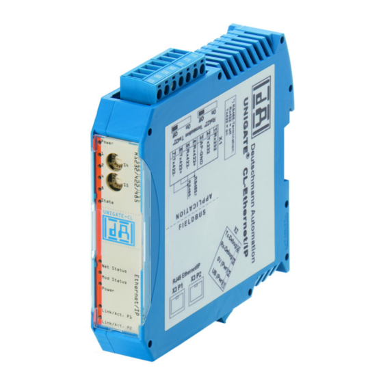
DEUTSCHMANN AUTOMATION UNIGATE CL Instruction Manual (62 pages)
Universal Fieldbus-Gateway, EtherNet/IP 2Port
Brand:
DEUTSCHMANN AUTOMATION
| Category:
Gateway
| Size: 2 MB
Table of Contents
Table of Contents
4
1 Information on CE Marking of the Module
9
EU Directive EMC
9
Scope of Application
9
Note Installation Guidelines
9
Installation of the Unit
9
Working on Switch Cabinets
9
2 Information for the Machine Manufacturers
10
Introduction
10
EU Machinery Directive
10
3 Introduction
11
UNIGATE ® CL Software Flow-Chart
12
UNIGATE ® Application Diagram
13
4 Operation Modes of the Gateway
14
Configuration Mode (Config Mode)
14
Test Mode
14
Data Exchange Mode
14
5 RS-Interface
15
RS-Interfaces at the UNIGATE ® CL
15
Buffer Sizes at the UNIGATE ® CL
15
Framing Check
15
6 SSI-Interface
16
Initiation of the SSI-Interface
16
Parameter
16
Resolution
16
SSI Encoder Type
16
Parameter Sample Frequency (Clock Stretch)
16
Parameter Encoder Monitoring (Check Encoder)
17
Hardware-Wiring
17
7 The Debug-Interface
18
Overview of the Debug-Interface
18
Starting in the Debug-Mode
18
Communication Parameter for the Debug-Interface
18
Possibilities with the Debug-Interface
18
Commands of the Debug-Interface
18
8 Mode of Operation of the System
19
General Explanation
19
Interfaces
19
Data Exchange
19
Possible Data Lengths
19
Startup Phase
19
9 Generating a Script
20
What Is a Script
20
Memory Efficiency of the Programs
20
What Can You Do with a Script Device
20
Independence of Buses
20
Further Settings at the Gateway
20
The Use of the Protocol Developer
21
10 Implemented Protocols in UNIGATE® CL with Universal Script
22
Protocol: Transparent
22
Data Structure
22
Protocol: Universal 232
22
Fieldbus Parameters
22
RS232 Parameter Table
23
Start Character (232 Start Character)
23
Length 232 (232 Length)
23
Timeout
23
End Character (232 End Character)
23
Communication Sequence
23
Protocol: 3964(R)
24
Data Structure 3964R
24
Protocol Definitions
24
Data Communication
24
Initiation of Data Communication by the Low-Priority User
24
Conflicts
24
Timeout Times
24
Retries
25
Initiation of Data Communication by the High-Priority User
25
Protocol Type 3964
25
Protocol: MODBUS-RTU
25
Notes
25
UNIGATE ® as MODBUS-Master
25
Preparation
25
Data Structure
26
Communication Sequence
26
UNIGATE ® as MODBUS-Slave
26
Preparation
26
UNIGATE ® as Modbus-ASCII Master
27
Protocol „Universal Modbus RTU Slave
27
Data Structure on the Fieldbus Side E.g.: PROFIBUS
27
Example: FC1 + FC2
27
Example: FC3 (Read Holding Register) + FC4 (Read Input Register)
28
Example: Write Single Coil FC5
29
Example: Write Single Register FC6
30
Example: Force Multiple Coils FC 15
31
Example: Preset Multiple Register FC16
32
Protocol „Universal Modbus RTU Master
33
Data Structure Fieldbus Side (E.g. PROFIBUS)
33
Data Structure Application Side
33
Configuration: Via Wingate Since Wcf Datei Version 396
34
Example: Read Coil Status FC1
35
Example: Read Input Status FC2
36
Example: Read Multiple Register FC3
37
Example: Read Input Registers FC4
38
Example: Force Single Coil FC5
38
Example: Preset Single Register FC6
39
Example: Force Multiple Coils FC15
39
Example: Preset Multiple Register FC16
40
Protocol „Universal Modbus ASCII Master/Slave
41
Protocol SSI
41
The Trigger Byte
41
The Length Byte
41
11 FTP-Server
42
Script-Update Via FTP
42
System Configuration Update Via FTP
42
12 WEB-Server
43
Server Side Includes (SSI)
43
HTML-Formulare
44
Examples
44
13 File System
45
14 Hardware Ports, Switches and Leds
46
Device Labeling
46
Connectors
46
Connector to the External Device (RS-Interface)
46
Connector Supply Voltage and DEBUG-Interface
47
Ethernet/Ip-Connector
47
Power Supply
47
Leds
48
LED "(Ethernet/Ip) Power
48
LED "Link/Act. P1
48
LED "Link/Act. P2
48
LED "Net State
48
LED "Mod State
48
LED "Power
48
LED "State
48
Leds (Error No. / Select ID)
49
Switches
49
Termination Rx 422 + Tx 422 (Serial Interface)
49
Rotary Coding Switches S4 + S5 (Serial Interface)
49
The Debug Cable for UNIGATE ® CL
49
15 Error Handling
50
Error Handling at UNIGATE ® CL
50
16 Installation Guidelines
52
Installation of the Module
52
Mounting
52
Removal
52
Wiring
52
Connection Systems
52
Power Supply
52
Equipotential Bonding Connection
52
Ethernet/Ip Communication Interface
53
Line Routing, Shield and Measures to Combat Interference Voltage
53
General Information on Line Routing
53
Shielding of Lines
53
17 Technical Data
55
Device Data
55
Interface Data
56
18 Commissioning Guide
57
Note
57
Components
57
Installation
57
Dimensional Drawing UNIGATE ® CL - Ethernet/Ip
57
Commissioning
57
Ethernet/Ip Connection
58
Connection to the Process Device
58
Shield Connection
58
Connecting the Supply Voltage
58
Project Planning
58
19 Servicing
59
Returning a Device
59
Downloading PC Software
59
20 Annex
60
Explanations of the Abbreviations
60
Hexadecimal Table
61
Advertisement
DEUTSCHMANN AUTOMATION UNIGATE CL Instruction Manual (62 pages)
Universal Fieldbus-Gateway
Brand:
DEUTSCHMANN AUTOMATION
| Category:
Gateway
| Size: 0 MB
Table of Contents
Table of Contents
3
1 Information on CE Marking of the Module
8
EU Directive EMC
8
Scope of Application
8
Note Installation Guidelines
8
Installation of the Unit
8
Working on Switch Cabinets
8
2 Information for the Machine Manufacturers
9
Introduction
9
EU Machinery Directive
9
3 Introduction
10
UNIGATE ® CL Software Flow-Chart
11
UNIGATE ® Block Diagram
12
UNIGATE ® Application Diagram
12
4 Operation Modes of the Gateway
13
Configuration Mode (Config Mode)
13
Test Mode
13
Data Exchange Mode
13
5 RS-Interface
14
RS-Interfaces at the UNIGATE ® CL
14
Buffer Sizes at the UNIGATE ® CL
14
Framing Check
14
6 SSI-Interface
15
Initiation of the SSI-Interface
15
Parameter
15
Resolution
15
SSI Encoder Type
15
Parameter Sample Frequency (Clock Stretch)
15
Parameter Encoder Monitoring (Check Encoder)
16
Hardware-Wiring
16
7 The Debug-Interface
17
Overview of the Debug-Interface
17
Starting in the Debug-Mode
17
Communication Parameter for the Debug-Interface
17
Possibilities with the Debug-Interface
17
Commands of the Debug-Interface
17
8 Mode of Operation of the System
18
General Explanation
18
Interfaces
18
Data Exchange Devicenet
18
Polling
18
Possible Data Lengths
18
9 Generating a Script
19
What Is a Script
19
Memory Efficiency of the Programs
19
What Can You Do with a Script Device
19
Independence of Buses
19
Further Settings at the Gateway
19
The Use of the Protocol Developer
20
Accuracies of the Baud Rates
20
Script Processing Times
21
10 Implemented Protocols in UNIGATE® CL with Universal Script
22
Protokoll: Transparent
22
Data Structure
22
Protocol: Universal 232
22
Data Structure
23
Fieldbus Parameters
23
RS232 Parameter Table
23
Communication Sequence
24
Protocol: 3964(R)
24
Data Structure 3964R
24
Protocol Definitions
24
Data Communication
24
Conflicts
25
Protocol Type 3964
25
Protocol: MODBUS-RTU
25
Notes
25
UNIGATE as MODBUS-Master
25
UNIGATE ® as MODBUS-Slave
26
UNIGATE ® as Modbus-ASCII Master
27
Protocol „Universal Modbus RTU Slave
27
Data Structure on the Fieldbus Side E.g.: PROFIBUS
27
Protocol „Universal Modbus RTU Master
33
Data Structure Fieldbus Side (E.g. PROFIBUS)
33
Data Structure Application Side
33
Configuration: Via Wingate Since Wcf Datei Version 396
34
Protocol „Universal Modbus ASCII Master/Slave
41
Protocol SSI
41
The Trigger Byte
41
The Length Byte
41
11 Hardware Ports, Switches and Leds
42
Device Labeling
42
Connectors
42
Connector to the External Device (RS-Interface)
42
Connector Supply Voltage and DEBUG-Interface
43
Devicenet-Connector
43
Power Supply
43
Leds
43
LED "(Bus) Power
43
LED "(Bus) State
43
LED "Power
44
LED "State
44
Leds 1 / 2 / 4 / 8 (Error No. / Select ID)
44
Switches
44
Termination Rx 422 + Tx 422 (Serial Interface)
44
Rotary Coding Switches S4 + S5 (Serial Interface)
44
Termination (Devicenet)
45
DIP-Switch
45
The Debug Cable for UNIGATE ® CL
45
12 Error Handling
46
Error Handling at UNIGATE ® CL
46
13 Installation Guidelines
48
Installation of the Module
48
Mounting
48
Removal
48
Wiring
48
Connection Systems
48
Devicenet Communication Interface
49
Line Routing, Shield and Measures to Combat Interference Voltage
49
General Information on Line Routing
49
14 Devicenet
51
The Product Code
51
EDS File
51
Sample EDS File
51
Devicenet™ Information
53
15 Technical Data
54
Device Data
54
Interface Data
55
16 Commissioning Guide
56
Note
56
Components
56
Installation
56
Dimensional Drawing UNIGATE ® CL - Devicenet
56
Commissioning
56
Setting the Devicenet™ Address and Baud Rate
56
Devicenet™ Connection
57
Connection to the Process Device
57
Connecting the Supply Voltage
57
Shield Connection
57
Project Planning
57
17 Servicing
58
Returning a Device
58
Downloading PC Software
58
18 Annex
59
Explanations of the Abbreviations
59
Hexadecimal Table
60
DEUTSCHMANN AUTOMATION UNIGATE CL Instruction Manual (49 pages)
Universal Fieldbus-Gateway PROFINET 2Port
Brand:
DEUTSCHMANN AUTOMATION
| Category:
Gateway
| Size: 1 MB
Table of Contents
Table of Contents
2
1 Information on CE Marking of the Module
7
EU Directive EMC
7
Scope of Application
7
Note Installation Guidelines
7
Installation of the Unit
7
Working on Switch Cabinets
7
2 Information for the Machine Manufacturers
8
Introduction
8
EU Machinery Directive
8
3 Introduction
9
UNIGATE ® CL Software Flow-Chart
10
UNIGATE ® Application Diagram
11
4 Operation Modes of the Gateway
12
Configuration Mode (Config Mode)
12
Test Mode
12
Data Exchange Mode
12
5 RS-Interface
13
RS-Interfaces at the UNIGATE CL
13
Buffer Sizes at the UNIGATE CL
13
Framing Check
13
6 SSI-Interface
14
Initiation of the SSI-Interface
14
Hardware-Wiring
15
7 The Debug-Interface
16
Overview of the Debug-Interface
16
Starting in the Debug-Mode
16
Communication Parameter for the Debug-Interface
16
Possibilities with the Debug-Interface
16
Commands of the Debug-Interface
16
8 Mode of Operation of the System
17
General Explanation
17
Interfaces
17
Data Exchange
17
Possible Data Lengths
17
Startup Phase
17
9 Generating a Script
18
What Is a Script
18
Memory Efficiency of the Programs
18
What Can You Do with a Script Device
18
Independence of Buses
18
Further Settings at the Gateway
18
The Use of the PROTOCOL DEVELOPER
18
10 Implemented Protocols in UNIGATE ® CL with Universal Script
20
Protocol: Transparent
20
Data Structure
20
Protocol: Universal 232
20
Data Structure
21
Fieldbus Parameters
21
RS232 Parameter Table
21
Start Character (232 Start Character)
21
Length 232 (232 Length)
21
End Character (232 End Character)
21
Communication Sequence
21
Protocol: 3964(R)
22
Data Structure 3964R
22
Protocol Definitions
22
Data Communication
22
Initiation of Data Communication by the Low-Priority User
22
Conflicts
22
Timeout Times
22
Retries
23
Initiation of Data Communication by the High-Priority User
23
Protocol Type 3964
23
Protocol: MODBUS-RTU
23
Notes
23
UNIGATE ® as MODBUS-Master
23
Preparation
23
Data Structure
24
Communication Sequence
24
UNIGATE ® as MODBUS-Slave
24
Preparation
24
Data Structure
25
Communication Sequence
25
UNIGATE ® as Modbus-ASCII Master
25
The Trigger Byte
25
The Length Byte
25
11 FTP-Server
26
Script-Update Via FTP
26
System Configuration Update Via FTP
26
12 WEB-Server
27
Server Side Includes (SSI)
27
HTML-Forms
28
Example
28
13 File System
29
14 Hardware Ports, Switches and Leds
30
Device Labeling
30
Connectors
30
Connector to the External Device (RS-Interface)
30
Connector Supply Voltage and DEBUG-Interface
31
Profinet-Connector
31
Power Supply
31
Leds
32
LED "(PROFINET) Power
32
LED "Link / Act. P1
32
LED "Link / Act. P2
32
LED "(PROFINET) State
32
LED "Power
32
LED "State
32
Leds 1 / 2 / 4 / 8 (Error No. / Select ID)
32
Switches
33
Termination Rx 422 + Tx 422 (Serial Interface)
33
Rotary Coding Switches S4 + S5 (Serial Interface)
33
The Debug Cable for UNIGATE® CL
33
15 Error Handling
34
Error Handling at UNIGATE ® CL
34
16 Installation Guidelines
35
Installation of the Module
35
Mounting
35
Removal
35
Wiring
35
Connection Systems
35
Power Supply
35
Equipotential Bonding Connection
35
PROFINET-IO Communication Interface
36
Line Routing, Shield and Measures to Combat Interference Voltage
36
General Information on Line Routing
36
Shielding of Lines
36
17 Technical Data
38
Device Data
38
Interface Data
39
18 Commissioning Guide
40
Note
40
Components
40
Installation
40
Dimensional Drawing UNIGATE ® CL - PROFINET-IO
40
Commissioning
40
PROFINET Address-Assignment
41
PROFINET Device Name
41
PROFINET Connection
41
Connection to the Process Device
41
Shield Connection
41
Connecting the Supply Voltage
41
Project Planning
41
Literature
42
19 Servicing
43
Returning a Device
43
Downloading PC Software
43
20 Annex
44
Explanations of the Abbreviations
44
Hexadecimal Table
45
21 EC Declaration of Conformity
46
Advertisement
Advertisement
Related Products
DEUTSCHMANN AUTOMATION UNIGATE CL-Fast Ethernet
DEUTSCHMANN AUTOMATION UNIGATE CL ProfibusDP
DEUTSCHMANN AUTOMATION UNIGATE CL - Powerlink
DEUTSCHMANN AUTOMATION UNIGATE CL - DeviceNet
DEUTSCHMANN AUTOMATION UNIGATE CL - RS
DEUTSCHMANN AUTOMATION UNIGATE CL EtherCAT
DEUTSCHMANN AUTOMATION UNIGATE CL-LONWorks Series
DEUTSCHMANN AUTOMATION UNIGATE CL-MPI
DEUTSCHMANN AUTOMATION UNIGATE CL-CANopen
DEUTSCHMANN AUTOMATION UNIGATE CL-FE
DEUTSCHMANN AUTOMATION Categories
Gateway
Microcontrollers
Controller
Control Unit
Industrial Electrical
More DEUTSCHMANN AUTOMATION Manuals
Login
Sign In
OR
Sign in with Facebook
Sign in with Google
Upload manual
Upload from disk
Upload from URL