Sign In
Upload
Manuals
Brands
Demag Manuals
Lifting Systems
DC-Com 2
Demag DC-Com 2 Manuals
Manuals and User Guides for Demag DC-Com 2. We have
2
Demag DC-Com 2 manuals available for free PDF download: Operating Instructions Manual
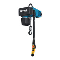
Demag DC-Com 2 Operating Instructions Manual (124 pages)
chain hoist
Brand:
Demag
| Category:
Lifting Systems
| Size: 11.26 MB
Table of Contents
Table of Contents
3
1 General
7
DC-Com Chain Hoist
7
DC-Com Documentation
7
Symbols/Signal Words
7
Information on the Operating Instructions
8
Liability and Warranty
8
Copyright
9
Use of Spare Parts
9
Definition of Personnel
9
Test and Inspection Booklet
10
After-Sales Service
10
2 Safety
11
General
11
Safety Signs on the Equipment
11
Intended Use
11
Hazards Which May be Caused by the Machine
12
Responsibility of the Owner
13
Operating Personnel Requirements
13
Personal Protection Equipment
14
Emergency Stop Device
14
Regular Inspections
14
3 Technical Data
16
Design Overview
16
Model Code
17
Selection Table
18
Electrical Key Values
20
Hoist Motor Data
20
Mains Connection Delay Fuse Links
23
Supply Lines 1
23
Hook Dimensions C
24
Noise Emission / Sound Pressure Level
26
Transport, Packing and Storage
26
Safety Instructions
26
Scope of Delivery
26
Transport Inspection
26
Packing
26
Storage
27
Surface Protection and Painting
27
Operating Conditions
28
4 Technical Description
29
Drive and Brake
29
Gearbox and Slipping Clutch
29
Chain Drive
30
Housing
30
Electrical Equipment
30
Control
30
7-Segment Display for Operating Status and Error Display
31
Software Version, Operating Hours, Number of Cycles, Operating Statuses
31
Central Service Enclosure
32
Control Pendant Height Adjustment / Control Cable
33
Control Pendant
33
Suspension
34
Trolley
36
5 Fitting
39
General
39
Safety Instructions for Assembly
39
Tightening Torques DC-Com Chain Hoist
41
Assembly Procedure
41
Connecting the Control Pendant
42
Suspending the Chain Hoist
43
Supporting Structure
43
Suspension Bracket
44
Control Cable
45
Techncal Data of the Control Cable
45
Handling the Control Cable
45
Height Adjustment of the Control Pendant
46
Mobile Control System
47
Line Connection
48
Circuit Diagrams and Control Cards
50
Circuit Diagram DC-Com 1 - 10 solo Hoist
50
Circuit Diagram with E 11 - E 34 Travel Drive
53
Control Card
53
Setting Parameters with the Control Pendant
55
General
55
Meaning of Keys
55
Meaning of Parameters
55
Starting Parameter Setting Mode
56
Setting the Lower Hook Position
58
6 Putting into Service for the First Time
59
Safety Instructions When First Putting the Unit into Service
59
Inspection Regulations
59
Inspection Prior to Putting into Service for the First Time
60
Inspections When First Putting into Service, Handing over
60
7 Operation
61
Safety Instructions for Operation
61
Switching on
62
Inspections When Starting Work
62
Functional Tests
62
Operation
63
General
63
Emergency Stop
66
Taking out of Service
67
Taking out of Service in the Case of Faults
67
Taking the Hoist out of Service on Finishing Work
67
Taking the Unit out of Service for Maintenance and Repairs
67
8 Maintenance/Repair
68
Safety Instructions for Maintenance/Repair
68
Basic Information on Maintenance
69
Routine Inspections
70
Prescribed Inspections
70
Service Life of the Contactor
70
Measures for Achieving Safe Working Periods S.W.P
71
General
71
Calculating the Actual Duration of Service S
71
Example: DC-Com 10-1000 1/1 H5 V4/1 in 1Am
72
General Overhaul GO
74
Inspection and Maintenance Schedule
74
Maintenance Work
76
Suspension
76
Electrical Equipment Cover
76
Dismantling the Chain Collector Box
77
Operating Limit Switch (as Standard for DC-Com 10 Reeving 2/1)
77
Checking the Operating Limit Switches
77
Checking the Operating Limit Switch Actuator
78
Chain Drive
79
Checking the Sprocket Wheel
79
Checking the Chain Guide
79
Checking the Guide Plate
79
Checking the Hoist Chain
79
Scope of Supply Chain Set
82
Available Hoist Chains
83
Replacing the Chain Set
84
Lubricating the Hoist Chain
87
Load Hook
88
Checking the Load Hook
88
Checking the Return Sprocket
88
Replacing the Hook Assembly, Reeving 1/1
89
Replacing the (Standard) Bottom Block with Internal Switch-Off Springs, Reeving 2/1
90
Replacing the (Optional) Bottom Block with External Switch-Off Springs, Reeving 2/1
91
Buffer (Only with Optional Operating Limit Switches for DC-Com 1-10 Reeving 1/1)
91
Checking the Swich-Off Buffer / Switch-Off Spring
91
Buffer Design
92
Brake
94
Brake Assignment
94
Check Brake Wear
94
Slipping Clutch
96
Checking the Slipping Clutch
96
Adjusting the Slipping Clutch
96
Gearbox / Oil Change
97
Replacing the Contactor on the Control Card
98
Replacing Cables
100
Replacing the Control Cable
100
9 Faults / Warnings
102
Safety Instructions for Faults / Warnings
102
7-Segment Display
103
General Messages
103
Warning Messages
104
Error Messages
105
10 Disassembly / Disposal
106
General
106
11 Accessories
107
Assemblies
107
12 Spare Parts
108
12.1 Overview
108
12.2 Motor
109
12.3 Parts on Gearbox
110
12.4 Chain Drive
112
12.5 Hook Assembly
114
Bottom Block with Internal Switch-Off Springs (Standard)
115
Bottom Block with External Switch-Off Springs (Option)
116
12.8 Electrical Equipment Cover
117
12.9 Control Pendant, Control Cable, Service Cover
118
Index
119
Advertisement
Demag DC-Com 2 Operating Instructions Manual (116 pages)
Brand:
Demag
| Category:
Chain Hoists
| Size: 10.36 MB
Table of Contents
Table of Contents
3
1 General
7
DC-Com Chain Hoist
7
DC-Com Documents
7
Symbols/Signal Words
7
Information on the Operating Instructions
8
Liability and Warranty
9
Copyright
9
Use of Spare Parts
9
Definition of Personnel
10
Test and Inspection Booklet
10
After-Sales Service
10
2 Safety
12
General Information on Safety
12
Safety Signs on the Equipment
12
Intended Use
12
Hazards that Can be Caused by the Machine
13
Responsibility of the Owner
14
Operating Personnel Requirements
14
Personal Protection Equipment
15
Emergency-Stop Device
15
Regular Inspections
16
3 Technical Data
17
Design Overview
17
Model Code
18
Selection Table
19
Electric Key Data
20
Hoist Motor Data
20
Mains Connection Delay Fuse Links
23
Supply Cables
23
Hook Dimension C
24
Noise Emission/Sound Pressure Level
25
Transport, Packing and Storage
25
Safety Instructions
25
Scope of Delivery
25
Transport Inspection
25
Packing
25
Storage
26
Materials
26
Linings
26
Housing
26
Surface Protection and Paint Finish
26
Operating Conditions
27
4 Technical Description
28
Drive and Brake
28
Gearbox and Slipping Clutch
28
Chain Drive
28
Electric Equipment
28
Control System
28
7-Segment Display for Operating Status and Fault Display
29
Display of Software Version, Operating Hours, Number of Cycles
30
Central Service Enclosure
31
Control Pendant/Control Cable Height Adjustment
31
Control Pendant
31
5 Assembly
32
General
32
Safety Instructions for Assembly
32
DC-Com Chain Hoist Tightening Torques
34
Installation Procedure
34
Connecting the Control Pendant
35
Control Cable
36
Control Cable Technical Data
36
Handling the Control Cable
36
Control Pendant Height Adjustment
37
Mobile Control System
38
Suspending the Chain Hoist
40
Supporting Structure
40
Suspension Bracket
41
Mains Connection
42
Circuit Diagrams and Control Boards
44
DC-Com 1 - 10 solo Hoist Circuit Diagram
44
Circuit Diagram with E11 - E34 DC Travel Drive
47
Control Board
47
Programming Parameters with the Control Pendant
49
General
49
Meaning of the Buttons
49
Meaning of the Parameters
49
Starting Parameter Programming Mode
50
Adjusting the Lower Hook Position
52
6 Putting into Service for the First Time
53
Safety Instructions When Putting into Service for the First Time
53
Inspection Regulations
53
Inspections before Putting into Service for the First Time
54
Checks on Entering Service, Handover
54
7 Operation
55
Safety Instructions for Operation
55
Switching on
56
Checks When Starting Work
56
Function Checks
56
Operation
57
Safety During Operation
57
Load Pick-Up
57
Moving the Load
58
Load Distribution
58
Emergency-Stop Device Operating Function
59
Slipping Clutch Operating Function
59
Lifting Path Limiter Operating Function
59
Emergency Stop
59
Taking the Equipment out of Operation
60
Taking the Equipment out of Service When Faults Occur
60
Taking the Equipment out of Service at the End of the Shift
60
Taking the Equipment out of Service for Maintenance and Repairs
60
8 Maintenance/Repair
62
Safety Instructions for Maintenance and Repair Work
62
Basic Maintenance Requirements
63
Regular Inspections
64
Required Tests and Inspections
64
Special Operating Conditions
64
Service Life of the Contactor
64
S.W.P. Measures for Achieving Safe Working Periods
65
General
65
Calculating the Actual Duration of Service S
66
Example: DC-Com 10-1000 1/1 H5 V4/1 in 1Am
66
GO General Overhaul
68
Maintenance Schedule
68
Maintenance Work
70
Suspension
70
Electric Equipment Cover
70
Removing the Chain Collector Box
71
Operating Limit Switches (Standard for DC-Com 10 with 2/1 Reeving)
71
Checking Operating Limit Switches
71
Checking the Operating Limit Switch Actuator
72
Chain Drive
73
Checking the Sprocket Wheel
73
Checking the Chain Guide
73
Checking the Guide Plate/Chain Entry Plate
74
Checking the Hoist Chain
74
Chain Set Scope of Supply
76
Available Hoist Chains
77
Replacing the Chain Set
78
Lubricating the Hoist Chain
82
Load Hook
83
Checking the Load Hook
83
Hook Safety Catch
83
Checking the Return Sprocket
83
Replacing the Hook with Fittings for 1/1 Reeving
84
Replacing the Bottom Block (Standard) with Internal Cut-Off Springs for 2/1 Reeving
85
Replacing the Bottom Block (Option) with External Cut-Off Springs for 2/1 Reeving
86
Buffer (Only with Optional Operating Limit Switches DC-Com 1-10 with 1/1 Reeving)
86
Checking the Cut-Off Buffers/Cut-Off Springs
86
Buffer Arrangement
87
Brake
88
Brake Assignment
88
Check Brake Wear
88
Slipping Clutch
90
Checking the Slipping Clutch
90
Adjusting the Slipping Clutch
90
Gearbox/Oil Change
91
Replacing the Contactor on the Control Board
92
Replacing the Control Cable
94
9 Malfunctions/Warnings
96
Safety Instructions for Malfunctions/Warnings
96
7-Segment Display
96
Operating Statuses/General Messages
97
Warning Messages
98
Error Messages
99
10 Disassembly/Disposal
100
General
100
11 Accessories
101
Assemblies
101
12 Spare Parts
102
12.1 Overview
102
12.2 Motor
103
12.3 Parts on the Gearbox
104
12.4 Chain Drive
106
12.5 Hook Assembly
108
Bottom Block with Internal Cut-Off Springs (Standard)
109
Bottom Block with External Cut-Off Springs (Option)
110
12.8 Electric Equipment Cover
111
12.9 Control Pendant, Control Cable, Service Cover
112
Index
113
Advertisement
Related Products
Demag DC-Com 10
Demag DC-Com 1
Demag DC-Com 5
Demag Categories
DC Drives
Transmitter
Construction Equipment
Lifting Systems
Chain Hoists
More Demag Manuals
Login
Sign In
OR
Sign in with Facebook
Sign in with Google
Upload manual
Upload from disk
Upload from URL