
Related Manuals for DEMAG DC-Com 1


Summary of Contents for DEMAG DC-Com 1
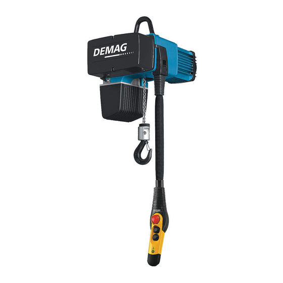
- Page 1 Distributed by Ergonomic Partners Sales@ErgonomicPartners.com www.ErgonomicPartners.com Tel: 314-884-8884 Operating instructions/accessories/component parts Demag DC-Com 1 - 10 chain hoist 291113 en GB 214 802 44 720 IS 817...
- Page 2 Please fill in the following table before first putting the unit into service. This provides you with definitive documentation of your Demag DC chain hoist and important information if you ever have to contact the manufacturer or his representative. Owner...
-
Page 3: Table Of Contents
Table of contents General..................................7 DC-Com chain hoist ..............................7 DC-Com documents..............................7 Symbols/signal words..............................7 Information on the operating instructions ........................8 Liability and warranty..............................9 Copyright ..................................9 Use of spare parts ............................... 9 Definition of personnel............................... 10 Test and inspection booklet............................ - Page 4 Suspension bracket ..............................41 Mains connection ..............................42 Circuit diagrams and control boards.......................... 44 5.9.1 DC-Com 1 - 10 solo hoist circuit diagram........................44 5.9.2 Circuit diagram with E11 - E34 DC travel drive ......................47 5.9.3 Control board................................47 5.10...
- Page 5 Replacing the bottom block (standard) with internal cut-off springs for 2/1 reeving..........85 8.5.6.6 Replacing the bottom block (option) with external cut-off springs for 2/1 reeving ............. 86 8.5.7 Buffer (only with optional operating limit switches DC-Com 1-10 with 1/1 reeving) ..........86 8.5.7.1 Checking the cut-off buffers/cut-off springs....................... 86 8.5.7.2 Buffer arrangement ..............................
- Page 6 Malfunctions/warnings ............................... 96 Safety instructions for malfunctions/warnings ......................96 7-segment display ..............................96 Operating statuses/general messages........................97 Warning messages..............................98 Error messages ................................. 99 Disassembly/disposal .............................. 100 10.1 General..................................100 Accessories ................................101 11.1 Assemblies ................................101 Spare parts ................................102 12.1 Overview .................................
-
Page 7: General
Safety instructions and information must be followed. Exercise particular caution to ensure that accidents, injuries and damage are avoided in such cases. Locally applicable accident prevention regulations and general safety regulations must also be followed. The documents can be ordered from the relevant Demag office. -
Page 8: Information On The Operating Instructions
They must be kept in the immediate vicinity. Demag chain hoists are delivered ready for operation as a complete machine with a control pendant or as partly completed machinery without a control pendant. -
Page 9: Liability And Warranty
For operation of the installation, the manufacturer of the installation must provide additional operating instructions as the result of the risk assessment, as required, and inform the owner about any remaining hazards. A declaration of incorporation is enclosed for a chain hoist supplied as partly completed machinery which is as‐ sembled with additional parts to form a machine that is ready for operation. -
Page 10: Definition Of Personnel
Definition of personnel The manufacturer is the person who: manufactures the equipment under his or her own name and places it on the market for the first time; resells other manufacturers' equipment under his or her own name, whereby the reseller is not considered to be the manufacturer provided the name of the manufacturer (as in 1.) appears on the equipment;... - Page 11 Please keep the serial or order number (see test and inspection booklet, load capacity plate on the crane) for any correspondence or spare part orders. Specifying this data ensures that you receive the correct information or the required spare parts. Demag Cranes & Components GmbH Telephone: +49 (0)180 5741268 www.demagcranes.com...
-
Page 12: Safety
Knowledge of the contents of the operating instructions is one of the requirements necessary to protect personnel from hazards and to avoid malfunctions and, therefore, to operate the machine safely and reliably. Any conversions, modifications or additions to the machine are prohibited unless approved by Demag in writing. Safety signs on the equipment Any pictograms, signs or labels on the machine must be obeyed and must not be removed. -
Page 13: Hazards That Can Be Caused By The Machine
DC chain hoists are designed for operation at temperatures from - 20 °C to + 45 °C. At extreme temperatures and in aggressive atmospheres or conditions differing from those specified in the "Operating conditions" section, the owner must implement special measures after consulting Demag. Use of the control pendant Powered lifting and lowering and, if applicable, cross-travel and long-travel motions are controlled by means of the corresponding control elements on the control unit. -
Page 14: Responsibility Of The Owner
Responsibility of the owner Information on safety at work refers to the regulations of the European Union that apply when the machine is manufactured. The owner is obliged to ensure that the specified industrial safety measures comply with the latest rules and regulations and to observe new regulations during the entire service life of the machine. -
Page 15: Personal Protection Equipment
Personal protection equipment When work is carried out on or with the installation, the following protective equipment is recommended to be worn according to the owner's hazard assessment: ● Protective clothing, closely fitting working clothes (low tear strength, no loose sleeves, no rings or any other jewellery, etc.);... -
Page 16: Regular Inspections
Regular inspections The owner of the machine may be obliged to carry out regular inspections by national industrial safety legislation and regional regulations. In Germany, this is specified by the accident prevention regulations for winches, hoists and towing devices (BGV D8) and the accident prevention regulations for cranes (BGV D6), for example. These specify that ●... -
Page 17: Technical Data
Technical data Design overview Fig. 4 Single-fall design Item Designation Item Designation Item Designation Electric equipment cover Chain guide Adjusting mechanism for control cable Cut-off buffer for operating limit switch Control system Chain sprocket Hook assembly with load capacity Elapsed operating time counter Round section steel chain plate Slipping clutch... -
Page 18: Model Code
Hook path [m] Reeving Load capacity [kg] Size DC-Pro product range DC-Pro product range DC-Pro 2-stage chain hoist (Demag chain hoist) DC-ProDC 2-stage chain hoist for direct control DCM-Pro 2-stage Manulift DC-ProCC 2-stage chain hoist for conventional contac‐ tor control... -
Page 19: Selection Table
Selection table Load ca‐ Reeving Chain size Lifting speed Standard Max. weight Size Group of mechanisms Motor size pacity for hook path DIN EN 14492 hook path Chain from 01/2014 until 12/2013 at 50 Hz at 60 Hz hoist [kg] DC-Com FEM/ISO FEM/ISO... -
Page 20: Electric Key Data
N min. N max. N max. φN max. [kW] [rpm] 220-240 V, 50 Hz, 3 ~ (CE) 0,05 1,75 2,10 2,10 1,45 0,48 DC-Com 1 ZNK 71 B 8/2 0,18 2950 2,10 2,80 2,80 2,75 0,46 0,07 1,80 2,10 2,35 1,45... - Page 21 N max. N max. φN max. [kW] [rpm] 220-240 V, 60 Hz, 3 ~ (CE / 0,06 2,10 2,50 2,50 1,45 0,47 DC-Com 1 ZNK 71 B 8/2 0,22 3525 2,50 3,35 3,35 2,75 0,45 0,09 2,10 2,50 2,80 1,45...
- Page 22 Lifting speeds until 09/2008 (no longer available) Size Motor size No. of Starts/h Min./max. currents and start-up current poles N min. N max. N max. φN max. [kW] [rpm] 220-240 V, 50 Hz, 3 ~ (CE) 0,09 2,10 2,20 2,50 1,25 0,52 DC-Com 2...
-
Page 23: Mains Connection Delay Fuse Links
440-480 V 575 V Frequency 50 Hz 60 Hz Size Motor size ZNK 71 A 8/2 DC-Com 1 ZNK 71 B 8/2 DC-Com 2 ZNK 71 B 8/2 DC-Com 5 ZNK 80 A 8/2 ZNK 100 A 8/2 DC-Com 10 ZNK 100 B 8/2 Tab. -
Page 24: Hook Dimension C
Higher lifting speeds may require the use of larger chain collector boxes, see "Buffer arrangement", Page 87 Dimensions C and C1 decrease when a short suspension bracket is used: by 38 mm for DC-Com 1-5 and by 33 mm for DC-Com 10. -
Page 25: Noise Emission/Sound Pressure Level
3.7.4 Packing Demag chain hoists, the accessories and the trolleys are shipped in cardboard packing. If no agreement has been made on the return of the packing material, separate the materials according to type and size and make them available for further use or recycling. -
Page 26: Storage
3.7.5 Storage Until they are installed, the equipment and accessories must be kept closed and may only be stored under the following conditions: ● Do not store outdoors. ● Store in dry and dust-free places, relative air humidity: max. 60%. ●... -
Page 27: Operating Conditions
Tab. 19 Demag chain hoists operating outdoors should be provided with a cover for protection against the weather or chain hoists, trolleys and travel drives should be kept under shelter if they are not in use. Special operating conditions may be agreed with the manufacturer in individual cases. -
Page 28: Technical Description
The dimension tolerances of this chain have been precisely adapted to the chain drive. We therefore urgently recommend that the Demag special chain be used to ensure safe opera‐ tion. The maximum service life of the chain can only be reached if the specified regular lubrications are correctly carried out. -
Page 29: 7-Segment Display For Operating Status And Fault Display
As standard, the control system features the following characteristics: ● Operating limit switches for lifting and lowering (optional for DC-Com 1 - 10 with 1/1 reeving, standard for DC- Com 10 with 2/1 reeving); ● Plug-in connections for control pendant, power supply, motor connection, brake, operating limit switches;... -
Page 30: Display Of Software Version, Operating Hours, Number Of Cycles
The following data can be read: ● Software version Fig. 8, Page 30, ● Operating hours Fig. 9, Page 30, ● Operating statuses "Operating statuses/general messages", Page 97, ● Warning messages "Warning messages", Page 98, ● Error messages "Error messages", Page 99. 4.4.3 Display of software version, operating hours, number of cycles Display of software version... -
Page 31: Central Service Enclosure
Central service enclosure Fig. 11 All important service work can be carried out at a central point, the service enclosure. The relevant connectors for power supply, control pendant and travel drive are arranged under the impact-resistant plastic cover. The chain is also lubricated from this point. -
Page 32: Assembly
Despite detailed information, errors cannot be excluded when the installation is assembled by the customer. For this reason, we recommend that this work be carried out by our trained specialists or by persons authorised by The wiring of the Demag chain hoist complies in all respects with current DIN VDE and accident prevention regu‐ lations. - Page 33 The arrow symbol on the switching elements must correspond to the direction of movement. Electric safety The chain hoist operating instructions must be referred to when Demag chain hoists are used. These operating instructions only contain standard circuit diagrams. Depending on the chain hoist type, an order- specific circuit diagram may apply.
-
Page 34: Dc-Com Chain Hoist Tightening Torques
Loose connections Loose connections are a danger to life and limb and a risk of damage to the machine. Metal nuts featuring a locking element (self-locking nuts) are mainly used for Demag chain hoists. – Self-locking nuts must not be replaced by other types of nut. -
Page 35: Connecting The Control Pendant
Connecting the control pendant Fig. 12 The control pendant is of plug-in design. The connector on the end of the control cable is locked in the bayonet sleeve and can be turned. If a connector is not locked, it can be pulled out and must be locked again by pressure. Unless the chain hoist is supplied with the control pendant fitted, connect the DSC control pendant with the con‐... -
Page 36: Control Cable
Control cable 5.6.1 Control cable technical data Item Designation Hose pocket Control cable retaining latch Control cable retaining bolt, tightening torque 11 Nm Hook path Cable lengths 0,8 m - 2,8 m 0,8 m - 3,8 m 3,8 m - 6,8 m 6,8 m - 9,8 m Tab. -
Page 37: Control Pendant Height Adjustment
5.6.3 Control pendant height adjustment Fig. 15 Control cable locking mechanism engaged Control cable locking mechanism released Undo the screws of the service cover. Open and disconnect the service cover. Remove and open the bag with the control cable. Take the control cable out of the bag. Slide the latch of the control cable locking mechanism upwards and hold it in place. -
Page 38: Mobile Control System
5.6.4 Mobile control system Component parts Item Designation comprising Order no. 11-pole + PE flat cable 720 139 45 Socket enclosure Mounting frame Connector enclosure cpl. 720 187 45 VC-AMS8 pin insert Flat cable union Bayonet lock VC-MP-1-R-M25 bush enclosure Connector adapter cpl. -
Page 40: Suspending The Chain Hoist
Suspending the chain hoist 5.7.1 Supporting structure DANGER Overload Danger to life and limb if the supporting structure is overloaded. The support superstructure must be designed for the maximum load caused by operation of the chain hoist when it is used as intended. Hoist units that have a load capacity greater than or equal to 1000 kg must be provided with overload protection to DIN EN 14492-2. -
Page 41: Suspension Bracket
5.7.2 Suspension bracket 43215244.eps Fig. 18 DC-Com 1 - 5 suspension bracket opened DC-Com 10 2/1 reeving DC-Com 10 1/1 reeving Spacer tube WARNING Overload Danger to life and limb if the components are overloaded. – The suspension/support structure for the chain hoist must be designed to accommodate the loads. -
Page 42: Mains Connection
Designation Item Designation Item Designation Strain relief attachment Sealing sleeve Mains connection DC-Com 1 - 5 Strain relief attachment 4-pole connector Recess for round cable DC-Com 10 Connector enclosure Recess for flat cable Tab. 27 The mains connection cable, the mains connection fuse links and any devices to disconnect and switch the po‐... - Page 43 ● Finally insert the mains cable into the opening in the gearbox housing and secure it with the strain relief clamp. For DC-Com 1 to 5 units, the strain relief clamp must be turned to match the shape of the cable depending on the cable type (flat or round cable).
-
Page 44: Circuit Diagrams And Control Boards
Circuit diagrams and control boards 5.9.1 DC-Com 1 - 10 solo hoist circuit diagram Fig. 20... - Page 45 Fig. 21...
- Page 46 Fig. 22...
-
Page 47: Circuit Diagram With E11 - E34 Dc Travel Drive
5.9.2 Circuit diagram with E11 - E34 DC travel drive For further circuit diagrams with E11 - E34 travel drives, see Tab. 3, Page 7 E11-E34 DC travel drive assembly instructions (II). For further information on E11 - E34 travel drives, see Tab. 3, Page 7 E11-E34 DC travel drive assembly in‐ structions (I). - Page 48 Item Designation Terminal strip Function Contactor On/off Transformer Plug-and-socket con‐ Line nector Fork light barrier Pulse generator IR transmitter diode IR interface 7-segment LED Multi-function display, e.g.: elapsed operating time counter, status indicator, error code display Plug-and-socket con‐ Lifting limit switch nector Dummy plug (Optional) trolley...
-
Page 49: Programming Parameters With The Control Pendant
5.10 Programming parameters with the control pendant 5.10.1 General Parameters can be programmed to adapt the chain hoist to specific application requirements. The parameters can be programmed using the control pendant together with the 7-segment display on the underside of the chain hoist. -
Page 50: Starting Parameter Programming Mode
5.10.4 Starting parameter programming mode Fig. 27 1st step: 2nd step: 3rd step: Actuate emergency stop. Press and hold down the "Lifting" button and When "P." is displayed, release the "Lifting" unlock emergency stop. Wait for approx. 10 button. seconds. 7-segment display: 8. - Page 51 Fig. 29 7th step: 8th step: 9th step: Press the "Lifting" button to select the currently To set a different value, press the "Lowering" The value is again selected by using the "Lift‐ displayed parameter. The value selection button until the required value is shown in the ing"...
-
Page 52: Adjusting The Lower Hook Position
5.11 Adjusting the lower hook position Fig. 31 Item Designation Item Designation Buffer (limit switch option) Limit stop Damping plate Unloaded chain fall Buffer plate Tab. 37 Ensure that the hook assembly touches the ground in the lower hook position when determining the hook path/ lifting height. -
Page 53: Putting Into Service For The First Time
Putting into service for the first time Safety instructions when putting into service for the first time The machine may only be handed over when its safety has been verified by means of a corresponding check "Checks on entering service, handover", Page 54. WARNING Safe operation of the machine is not yet ensured when it is first put into operation. -
Page 54: Inspections Before Putting Into Service For The First Time
Inspections before putting into service for the first time The owner is obliged to carry out the following checks before the unit is put into operation for the first time: Activity Section Check Check continuity of the PE conductor connection Check emergency-stop device Check direction of movement ... -
Page 55: Operation
Operation Safety instructions for operation WARNING Incorrect operation Risk of injury due to incorrect operation. Incorrect operation may result in severe injury or damage to property. The equipment may only be operated by authorised and instructed personnel in compliance with all accident-prevention and safety regulations. National regulations for the use of cranes and lifting appliances must be observed and followed. -
Page 56: Switching On
In this case, the owner must ensure safe operation or take the machine out of service until measures for safe operation have been clarified and implemented in agreement with Demag or other relevant bodies. In the event of a stoppage (e.g. if defects regarding safe and reliable operation are detected, in emergency situa‐... -
Page 57: Operation
Operation 7.3.1 Safety during operation DANGER Danger of broken chain and falling load The chain may break and loads may fall if the emergency limit position limiter is frequently approached. The chain hoist slipping clutch provides the emergency limit position limiter function for chain hoists that are not fitted with an operating limit switch or which have a defective operating limit switch. -
Page 58: Moving The Load
– When the load is lifted, the hook must move to an upright position to ensure that the safety catch is not sub‐ jected to a load by the load handling slings and, as a result, damaged. – Do not use the equipment to transport persons. –... -
Page 59: Emergency-Stop Device Operating Function
7.3.5 Emergency-stop device operating function When the emergency stop is actuated, the hoist motor is immediately disconnected from the electric power sup‐ ply, the mechanical brake is applied and it brings any movement to standstill. Operation can only be resumed by unlatching the emergency stop when no lifting or lowering commands are ap‐ plied (off-position interlock). -
Page 60: Taking The Equipment Out Of Operation
● continued operation of the machine constitutes no further hazard. Control pendant Demag chain hoists can be equipped with various control pendants, as required. Refer to the relevant documents for operation of the control pendant and button assignments, see Tab. 3, Page 7. - Page 61 Secure the mains connection switch with a padlock to prevent unauthorised or accidental reconnection to the supply. Only carry out maintenance work on the chain hoist when the load has been removed. Stop all moving parts and ensure that they cannot start moving while maintenance work is being carried out. Observe the relevant accident prevention regulations, instructions concerning intended use and statutory regulations for operation and maintenance.
-
Page 62: Maintenance/Repair
Loose connections Loose connections are a danger to life and limb and a risk of damage to the machine. Metal nuts featuring a locking element (self-locking nuts) are mainly used for Demag chain hoists. – Self-locking nuts must not be replaced by other types of nut. -
Page 63: Basic Maintenance Requirements
CAUTION Risk of injury. Oils and lubricants may pose a health hazard. Contact with these media may result in serious damage to health (poisoning, allergies, skin irritations, etc.). CAUTION Risk of injury. Leaking oils and lubricants are hazards due to the increased risk of slipping. Spilt oils and lubricants must be absorbed immediately by means of sawdust or oil absorbent and disposed of in an environmentally compatible way. -
Page 64: Regular Inspections
After finishing maintenance work Re-install safety devices as required by relevant regulations and check them for correct operation after finishing maintenance work. Carry out a test run at partial load after the chain hoist has been fully re-assembled. Ensure that the chain runs smoothly during the test run. -
Page 65: S.w.p. Measures For Achieving Safe Working Periods
Motor size Display value C for U 380 - 575 V Display value C for U 220 - 240 V DC chain hoist ZNK 71 ZNK 80 ZNK 100 A ZNK 100 B Tab. 41 Display value C specifies the expected service life of the contactor multiplied by 100000. This value was deter‐ mined under normal operating conditions. -
Page 66: Calculating The Actual Duration Of Service S
The actual duration of service is considerably increased if the chain hoist is only operated with partial loads. For a hoist unit operated on average with half load, for example, this results in an 8-fold increase in the actual duration of service;... - Page 67 Lifting and lowering (2+2) m/cycle = 4 m/cycle Operating time per day 8 h/day Days per inspection interval 250 days/inspection interval Tab. 45 Calculation 10 • 4 • 8 • 250 60 • 4 Tab. 46 With operating time read: 334 With estimated operating time: 333,3 In the operating time as read/estimated above, the chain hoist has transported the following loads: Fig.
-
Page 68: Go General Overhaul
8.3.5 GO general overhaul The chain hoists are designed for a period of use of at least 10 years until the first general overhaul is carried out. This is based on the condition that the specified group of mechanisms is not exceeded by the actual dura‐ tion of service. - Page 69 "S.W.P. measures for achieving safe working periods", Page 65 Fit chain hoist-specific Demag GO set The small parts (screws, washers ...) to be replaced when maintenance and assembly work is carried out are not listed separately. The checks and work speci‐...
-
Page 70: Maintenance Work
Maintenance work 8.5.1 Suspension If a check or inspection reveals that these components are worn beyond the specified dimensions or if cracks can be seen in these parts, they must be replaced at once. Suspension bracket Chain hoist DC 1 / 2 / 5 DC 10 Suspension bracket short... -
Page 71: Removing The Chain Collector Box
8.5.3 Removing the chain collector box Fig. 38 – Unscrew and remove service cover (1). – Place bag (2) with the control cable on the top of the chain hoist. – Disconnect spring (3) and place it in the recess in the chain collector box. –... -
Page 72: Checking The Operating Limit Switch Actuator
The chain hoist slipping clutch provides the emergency limit position limiter function for chain hoists that are not fitted with an operating limit switch or which have a defective operating limit switch. This emergency limit position limiter may only be approached in exceptional cases, i.e. it must not be approached in normal operation. High additional loads occur in the chain when the slipping clutch is tripped. -
Page 73: Chain Drive
8.5.5 Chain drive 8.5.5.1 Checking the sprocket wheel Since the chain sprocket is usually replaced together with the chain set, no further check is necessary under normal conditions. However, if you notice any uneven or harsh running in the chain drive mechanism, this may indicate wear. -
Page 74: Checking The Guide Plate/Chain Entry Plate
8.5.5.4 Checking the hoist chain Checking wear or deformation of the original Demag chain In addition to selecting the correct hoist unit for the given application, owners of chain hoists are obliged by rele‐ vant regulations – such as DIN 685 part 5 – to check the round-section steel chain continuously in operation to ensure optimum operating safety and, therefore, to avoid any accidents. - Page 75 Measuring wear or deformation of the original Demag chain Two methods can be used to measure wear or deformation of the original Demag chain: ● Measuring with a calliper gauge: - wear of a single chain link Fig. 44, Page 75;...
-
Page 76: Chain Set Scope Of Supply
● Chain guide with plate and cap, ● Chain guide plate, ● Buffers for upper and lower hook position, ● Tube of Demag chain grease, ● Retaining ring. The chain guide is pre-assembled, the chain is already fitted in the chain guide. -
Page 77: Available Hoist Chains
8.5.5.6 Available hoist chains Genuine Demag chain is a round-section steel chain tested to EN 818-7 which is subject to the regulations for round-section steel chains used in hoist applications issued by the Main Association of Industrial Employers' Mu‐ tual Insurance Societies, Central Department for Accident Prevention and the test criteria for round-section steel chains used in hoist applications and the inspection regulations to DIN 685 part 5 of Nov. -
Page 78: Replacing The Chain Set
8.5.5.7 Replacing the chain set Fig. 47 Before starting any maintenance work, switch the hoist off and secure it against reconnection to the power supply. To replace the chain set, proceed as follows: Open and remove service cover (1). Place bag (2) with the control cable on the chain hoist; pull out mains cable union (3) with fitted mains cable (4) and place to one side;... - Page 79 DC-Com 1 to 5: In the area power supply insert; DC Com 10: Fold cover (9) of the opening in the gearbox housing to the side.
- Page 80 Chain hoist with geared limit switch Fig. 49 Chain guide for DC 10 without geared limit switch Chain guide for DC 10 with geared limit switch Tab. 56 The chain guide has a larger opening on chain hoists that are equipped with a geared limit switch. See also ...
- Page 81 Fitting the chain anchorage for 2/1 reeving on DC 10 Fig. 52 ● Fit the chain anchorage before bolting the guide plates into position for DC 10 hoists with 2/1 reeving. Bolt chain anchorage halves (1) together (fig. A). ● Insert the bolted chain anchorage into the opening of the gearbox housing (fig. B). ●...
-
Page 82: Lubricating The Hoist Chain
Tightening torques [Nm] DC 1 / 2 DC 5 DC 10 Reeving Service cover Limit stop Chain anchorage halves 10,5 Guide plate Tab. 58 8.5.5.8 Lubricating the hoist chain After fitting, before a test load is lifted and before the hoist is put into operation as well as during normal opera‐ tion when no load is attached, the chain link contact areas must be lubricated with gear grease, part no. -
Page 83: Load Hook
8.5.6 Load hook 8.5.6.1 Checking the load hook Load capacity [kg] 1250 2000 Chain hoist DC-Com Reeving Load hook Type T010 T020 22,8 25,4 33,7 25,08 27,94 37,07 47,3 26,1 Dimensions [mm] 16,9 21,8 27,7 16,055 20,71 26,315 34,2 41,8 Max. -
Page 84: Replacing The Hook With Fittings For 1/1 Reeving
– that retaining pin (3) is correctly fitted when the hook and fittings are assembled. – Tighten housing bolts (4) according to the tightening torque table. Tightening torques [Nm] DC-Com 1 DC-Com 2 DC-Com 5 DC-Com 10 Hook assembly 25,0... -
Page 85: Replacing The Bottom Block (Standard) With Internal Cut-Off Springs For 2/1 Reeving
8.5.6.5 Replacing the bottom block (standard) with internal cut-off springs for 2/1 reeving Fig. 57 Remove guide half sections (1) (four M 6 bolts); Remove bottom block retaining bolts (2) and remove the bottom block. Insert the new chain into the bottom block in the same position and orientation (chain must operate without any twist);... -
Page 86: Replacing The Bottom Block (Option) With External Cut-Off Springs For 2/1 Reeving
DC 10 Bottom block with external cut-off springs 55,0 Tab. 62 8.5.7 Buffer (only with optional operating limit switches DC-Com 1-10 with 1/1 reeving) 8.5.7.1 Checking the cut-off buffers/cut-off springs Fig. 60 Buffer wear: Visually check the buffers in the course of the annual inspection. Check for damage, cracks and tears. -
Page 87: Buffer Arrangement
Chain hoist range Load hook side Chain collector box side DC-Pro 1 - 10 DC-Com 1 - 10 with operating limit switch DC-Pro 1 - 10 DC-Com 1 - 10 without operating limit switch DC-Pro 1 - 10 DC-Pro 15... -
Page 88: Brake
8.5.8 Brake 8.5.8.1 Brake assignment Load capacity Chain hoist Reeving Motor size Brake Max. brake displacement [kg] DC-Com [mm] 80 - 125 ZNK 71 B 8/2 160 - 250 BK03 315 - 500 ZNK 80 A 8/2 630 - 1000 ZNK 100 A 8/2 BK07 1250 - 2000... - Page 89 Until year of manufacture 03/2009 Fig. 63 Disconnect the chain hoist from the power supply (mains connection switch) and secure it against switching on again. ● Open the electric equipment cover. ● Disconnect brake connector. ● Dismantle brake. Measure brake wear with calliper gauge as follows: ●...
-
Page 90: Slipping Clutch
Tightening torques [Nm] DC 1 / 2 / 5 / 10 Brake Electric equipment cover Tab. 65 8.5.9 Slipping clutch 8.5.9.1 Checking the slipping clutch The slipping clutch provides the function of an emergency limit stop de‐ vice and overload protection for the chain hoist. The slipping clutch is initially adjusted in the factory. -
Page 91: Gearbox/Oil Change
Oil grades Demag special oil with wear-minimising additives, range of viscosity 10W-30 (part no. 664 020 44) for slipping clutch without speed monitoring. Malfunctions of the slipping clutch may occur if oils are used that are not ap‐ proved. Contact the manufacturer for ambient temperatures lower than -20 °C or higher than +45 °C. -
Page 92: Replacing The Contactor On The Control Board
8.5.11 Replacing the contactor on the control board Fig. 68 Unclip the contactor retaining mechanism by pressing locking tab (A) with your thumb. This carefully bends locking tab (A) away from the contactor. Then turn contactor (B) using your other hand until the mechanism no longer holds it. Then unclip second locking tab (A) on the opposite side (as described in step 1 above). - Page 93 The contactors are also socket-mounted for sizes DC 1 to 5 manufactured as of 02/2011 and can be individually replaced.
-
Page 94: Replacing The Control Cable
8.5.12 Replacing the control cable Fig. 69 DANGER Live components Danger to life and limb. Work on the electric equipment may only be carried out by a qualified electrician or by trained personnel. - Page 95 ● that the two pins on the enclosure line up with the bayonet lock. Assemble the control pendant "Connecting the control pendant", Page 35. Adjust the height of the control pendant "Control pendant height adjustment", Page 37. Tightening torques [Nm] DC-Com 1 DC-Com 2 DC-Com 5 DC-Com 10...
-
Page 96: Malfunctions/Warnings
Malfunctions/warnings Safety instructions for malfunctions/warnings WARNING Inappropriate fault elimination Danger to life and limb. Risk of damage to the machine. Faults may only be eliminated by qualified instructed personnel ( "Definition of personnel", Page 10) in compli‐ ance with the safety regulations. DANGER Live components Danger to life and limb. -
Page 97: Operating Statuses/General Messages
Error messages start with an "E" for error. Before any further movement is possible, the error message must be acknowledged using the emergency stop. Fig. 71 Safety function failure If a safety function fails, the equipment must not be operated until it is repaired. Malfunctions The chain hoist can only function when it is correctly connected to the power supply. -
Page 98: Warning Messages
Warning messages In general, all warning messages are generated by comparison of the actual and theoretical speed. There may be various causes for a difference in speed: ● incorrectly adjusted slipping clutch; ● a binding brake or ● a dirty or defective speed sensor. These causes may result in frequent warning messages. -
Page 99: Error Messages
Error messages Fig. 74 Display examples Item Display Malfunction/event Possible cause Remark E.1. Chain hoist is blocked. Hardware error of control system. Check error message by actuating and unlocking the emer‐ gency stop. Then actuate Lowering. If necessary, remove suspended load. -
Page 100: Disassembly/Disposal
Disassembly/disposal 10.1 General WARNING Before disassembly, follow the safety instructions in "Maintenance/repair", Page 62 of these operating in‐ structions. Refer to "Assembly", Page 32 of these operating instructions for information on removing track sections, trol‐ leys and current collector trolleys. Other parts are removed in reverse order to assembly. Unless a return or disposal agreement has been concluded, separated components must be recycled after proper removal: ●... -
Page 101: Accessories
Accessories 11.1 Assemblies Fig. 75 Item Description Size Order no. Bottom block with cut-off springs (e.g. for hot applications) consisting of: Bottom block, cut-off springs, grooved pins with round head, load capacity DC-Com 10 2/1 715 431 45 plates DC Com 1/2 717 808 45 Return sprocket assembly, consisting of: 1 return sprocket, 1 pin, 1 retaining ring, 1 supporting washer, 2 thrust wash‐... -
Page 102: 12 Spare Parts
12 Spare parts 12.1 Overview 1/1 reeving 2/1 reeving 42764247.eps... -
Page 103: 12.2 Motor
71585033 Fan set ZNK 100A 4 Nm 71585133 Fan set ZNK 100B 4 Nm DC-Com 1 71784133 Motor set 240V50Hz 220 V - 240 V, 50 Hz, 9,5 Nm 71784233 Motor set 415V50Hz 380 V - 415 V, 50 Hz, 9,5 Nm... -
Page 104: 12.3 Parts On The Gearbox
12.3 Parts on the gearbox 42763847.eps... - Page 105 Suspension set DC 1- 5 71597433 Suspension set DC10 Year of manufacture 2004 to 2006 47997646 Gear oil/seal DC-Com1,2 DC-Com 1/2; 5,5 Nm; 0,35 litre 47997746 Gear oil/seal DC-Com5 DC-Com 5; 5,5 Nm; 0,5 litre 71591933 Gear oil/seal DC10 DC-Com 10; 5,5 Nm; 0,9 litre...
-
Page 106: 12.4 Chain Drive
12.4 Chain drive 1/1 reeving 2/1 reeving 42764346.eps... - Page 107 Item Part no. Qty. Designation Material Standard 71795033 Chain set DC/DCM 1/2 H 5 4,0 Nm 71795133 Chain set DC 1/2 H 8 4,0 Nm 71895033 Chain set DC/DCM 5 H 5 4,3 Nm 71895133 Chain set DC 5 H 8 4,3 Nm 75395033 Chain set DC10 1/1 H 5...
-
Page 108: 12.5 Hook Assembly
12.5 Hook assembly 42764045.eps Item Part no. Qty. Designation Material Standard 71778033 Hook fi ttings set DC-Com 2 6,8 Nm 71878033 Hook fi ttings set DC-Com 5 9,5 Nm 71578033 Hook fi ttings set DC-Com10 25 Nm 71851633 Hook safety catch set DC1-5 71551633 Hook safety catch set DC10 T04 21480106.tbl... -
Page 109: Bottom Block With Internal Cut-Off Springs (Standard)
12.6 Bottom block with internal cut-off springs (standard) 42764145.eps Item Part no. Qty. Designation Material Standard 71598533 Bottom block set DC 2/1 71544233 Bottom block half set DC10 2/1 83865633 Hook safety catch set GR. 5 x5 75262033 Load capacity plate set DC10 2/1 21474017.tbl... -
Page 110: Bottom Block With External Cut-Off Springs (Option)
12.7 Bottom block with external cut-off springs (option) 42778044.eps Item Part no. Qty. Designation Material Standard Bottom block with cut-off springs 83785233 Bottom block half set DK10 6,8 Nm 83865033 Load hook DC16/25 DK10/20 83865633 Hook safety catch set GR. 5 x5 83592833 Load capacity plate set DK10 21474019.tbl... -
Page 111: 12.8 Electric Equipment Cover
12.8 Electric equipment cover 42763945.eps Item Part no. Qty. Designation Material Standard 77326033 Control set DC1-15.230V 220 V - 240 V, 50/60 Hz; 3 Nm 77306033 Control set DC1-15.400V 380 V - 415 V, 50 Hz/380 V - 400 V, 60 Hz; 3 Nm 77336033 Control set DC1-15.575V 500 V - 525 V, 50 Hz / 575 V, 60 Hz;... -
Page 112: 12.9 Control Pendant, Control Cable, Service Cover
12.9 Control pendant, control cable, service cover 42764451.eps Item Part no. Qty. Designation Material Standard 71792033 Service cover set DC 2 5,5 Nm 71892033 Service cover set DC 5 5,5 Nm 71592033 Service cover set DC10 7,5 Nm 71881033 Control cable set 5m 11 Nm 71880933 Control cable set 8m... -
Page 113: Index
Index Actual load spectrum factor 66 Self-locking nuts 33 Actual duration of service 66 Special fittings 41 AC asynchronous motor 28 Starting and stopping frequency 64 Strain relief attachment 42 Strain relief hose 31 Switching cycles 30 Bayonet lock 35, 31, 95 Swivel lock 95 Bend protection sleeve 35 Buffer 52... - Page 114 Head of Plant Wetter Handling Technology & Drives Engineering & Development Material Handling U02241 Reproduction in whole or in part only with prior consent of Demag Cranes & Components GmbH, 58286 Wetter Subject to change. No liability for errors or omissions...
- Page 115 Head of Plant Wetter Handling Technology & Drives Engineering & Development Material Handling U02241 Reproduction in whole or in part only with prior consent of Demag Cranes & Components GmbH, 58286 Wetter Subject to change. No liability for errors or omissions...
- Page 116 PO Box 67 · 58286 Wetter (Germany) Distributed by Ergonomic Partners Sales@ErgonomicPartners.com www.ErgonomicPartners.com Tel: 314-884-8884 Reproduction in whole or in part only with prior consent of Demag Cranes & Components GmbH, 58286 Wetter (Germany) Subject to change. Not liable for errors or omissions.
Need help?
Do you have a question about the DC-Com 1 and is the answer not in the manual?
Questions and answers