Sign In
Upload
Manuals
Brands
Dell Manuals
Laptop
EMC PowerEdge T550
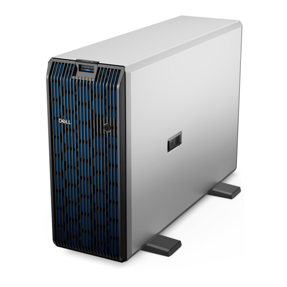
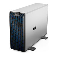
User Manuals: Dell EMC PowerEdge T550 Tower Server
Manuals and User Guides for Dell EMC PowerEdge T550 Tower Server. We have
4
Dell EMC PowerEdge T550 Tower Server manuals available for free PDF download: Installation And Service Manual
Dell EMC PowerEdge T550 Installation And Service Manual (185 pages)
Brand:
Dell
| Category:
Server
| Size: 51 MB
Table of Contents
Table of Contents
3
Chapter 1: About this Document
7
Chapter 2: Poweredge T550 System Overview
8
Front View of the System
9
Rear View of the System
18
Inside the System
20
Locating the Express Service Code and Service Tag
21
System Information Label
22
Chapter 3: Initial System Setup and Configuration
28
Setting up the System
28
Idrac Configuration
28
Options to Set up Idrac IP Address
28
Options to Log in to Idrac
29
Resources to Install Operating System
30
Options to Download Firmware
30
Options to Download and Install os Drivers
31
Downloading Drivers and Firmware
31
Chapter 4: Minimum to POST and System Management Configuration Validation
32
Minimum Configuration to POST
32
Configuration Validation
32
Error Messages
33
Chapter 5: Installing and Removing System Components
34
Safety Instructions
34
Before Working Inside Your System
35
After Working Inside Your System
35
Recommended Tools
36
Optional Front Bezel
36
Removing the Front Bezel
36
Installing the Front Bezel
37
System Feet
37
Removing the System Feet
37
Installing the System Feet
38
Optional Caster Wheels
39
Removing Caster Wheels
39
Installing Caster Wheels
40
System Cover
41
Removing the System Cover
41
Installing the System Cover
42
Air Shroud
44
Removing the Air Shroud
44
Installing the Air Shroud
44
Cooling Fans
45
Removing a Cooling Fan
45
Installing a Cooling Fan
46
Cooling Fan Cage
47
Removing the Cooling Fan Cage
47
Installing the Cooling Fan Cage
48
Fan Board Tray
49
Fan Board View
49
Removing the Fan Board Tray
50
Installing the Fan Board Tray
50
Front PERC Module
51
Removing the Front PERC Module
51
Installing the Front PERC Module
52
Drives
54
Removing a Drive Blank
54
Installing a Drive Blank
54
Removing a Drive Carrier
55
Installing a Drive Carrier
56
Removing the Drive from the Drive Carrier
57
Installing a Drive into the Drive Carrier
58
Removing a 3.5-Inch Drive Adapter from a 3.5-Inch Drive Carrier
59
Installing a 3.5-Inch Drive Adapter into the 3.5-Inch Drive Carrier
60
Removing a 2.5-Inch Drive from a 3.5-Inch Drive Adapter
61
Installing a 2.5-Inch Drive into a 3.5-Inch Drive Adapter
62
Drive Backplane
63
Removing the 3.5-Inch Drive Backplane
64
Installing the 3.5-Inch Drive Backplane
65
Removing the 2.5-Inch Drive Backplane
66
Installing the 2.5-Inch Drive Backplane
67
Drive Bays
68
Removing the Drive Bay Cage Blank
68
Installing the Drive Bay Cage Blank
70
Removing a Drive Bay
71
Installing a Drive Bay
73
Cable Routing
75
Optional Optical Drive
97
Removing the Optical Drive Blank
97
Installing the Optical Drive Blank
97
Removing the Optical Drive
98
Installing the Optical Drive
99
Optional Tape Backup Unit
100
Removing the Tape Backup Unit Blank
100
Installing the Tape Backup Unit Blank
101
Removing the Tape Backup Unit
102
Installing the Tape Backup Unit
103
Front IO Module
104
Removing the Front IO Module
104
Installing the Front IO Module
105
System Memory
107
System Memory Guidelines
107
General Memory Module Installation Guidelines
108
Removing a Memory Module
108
Installing a Memory Module
109
Optional BOSS S2 Module
110
Removing the BOSS S2 Module
110
Installing the BOSS S2 Module
112
Removing the BOSS S2 Card Carrier
113
Installing the BOSS S2 Card Carrier
115
M.2 BOSS Card
116
Removing the M.2 SSD Module
116
Installing the M.2 SSD Module
116
Optional Internal USB Card
117
Removing the Internal USB Module
117
Installing the Internal USB Module
118
Internal USB Memory Key
119
Removing the Internal USB Memory Key
119
Installing the Internal USB Memory Key
119
Optional IDSDM Module
119
Removing the IDSDM Module
119
Installing the IDSDM Module
120
Microsd Card
121
Removing the Microsd Card
121
Installing the Microsd Card
122
Expansion Cards
123
Expansion Card Installation Guidelines
123
Removing a Expansion Card
128
Installing an Expansion Card
129
GPU Card Holder
131
Removing the GPU Card Holder
131
Installing the GPU Card Holder
131
Optional GPU Card
132
Removing the GPU Card
132
Installing the GPU Card
134
GPU Riser
135
Removing the GPU Riser
135
Installing the GPU Riser
136
Processor and Heat Sink Module
137
Removing the Processor and Heat Sink Module
137
Removing the Processor
139
Installing the Processor
141
Installing the Processor and Heat Sink Module
145
Optional OCP Card
147
Removing the OCP Card
147
Installing the OCP Card
149
Optional Serial COM Port
151
Removing the Serial COM Port
151
Installing the Serial COM Port
152
System Battery
153
Replacing the System Battery
153
Intrusion Switch Module
154
Removing the Intrusion Switch Module
154
Installing the Intrusion Switch Module
155
Power Supply Unit
156
Hot Spare Feature
156
Removing a Power Supply Unit Blank
157
Installing a Power Supply Unit Blank
157
Removing a Power Supply Unit Adapter
158
Installing a Power Supply Unit Adapter
158
Removing a AC Power Supply Unit
159
Installing a AC Power Supply Unit
160
Power Interposer Board
162
PIB Board View
162
Removing the Power Interposer Board
162
Installing the Power Interposer Board
163
System Board
164
Removing the System Board
164
Installing the System Board
165
Restoring Service Tag Using Easy Restore
167
Manually Updating Service Tag
167
Trusted Platform Module
168
Upgrading the Trusted Platform Module
168
Removing the TPM
168
Installing the TPM
168
Initializing TPM for Users
169
Initializing the TPM 1.2 for Users
169
Initializing the TPM 2.0 for Users
169
Chapter 6: Jumpers and Connectors
170
System Board Connectors
170
System Board Jumper Settings
172
Disabling a Forgotten Password
172
Chapter 7: System Diagnostics and Indicator Codes
174
Status LED Indicators
174
System Health and System ID Indicator Codes
175
Idrac Quick Sync 2 Indicator Codes
175
Idrac Direct LED Indicator Codes
176
NIC Indicator Codes
177
Power Supply Unit Indicator Codes
177
Drive Indicator Codes
179
Using System Diagnostics
180
Dell Embedded System Diagnostics
180
Running the Embedded System Diagnostics from the Dell Lifecycle Controller
180
Running the Embedded System Diagnostics from Boot Manager
181
System Diagnostic Controls
181
Chapter 8: Getting Help
182
Recycling or End-Of-Life Service Information
182
Contacting Dell Technologies
182
Accessing System Information by Using QRL
182
Quick Resource Locator for Poweredge T550 System
183
Receiving Automated Support with Supportassist
183
Chapter 9: Documentation Resources
184
Advertisement
Dell EMC PowerEdge T550 Installation And Service Manual (185 pages)
Brand:
Dell
| Category:
Laptop
| Size: 51 MB
Table of Contents
Table of Contents
3
Chapter 1: About this Document
7
Chapter 2: Poweredge T550 System Overview
8
Front View of the System
9
Rear View of the System
18
Inside the System
20
Locating the Express Service Code and Service Tag
21
System Information Label
22
Chapter 3: Initial System Setup and Configuration
28
Setting up the System
28
Idrac Configuration
28
Options to Set up Idrac IP Address
28
Options to Log in to Idrac
29
Resources to Install Operating System
30
Options to Download Firmware
30
Options to Download and Install os Drivers
31
Downloading Drivers and Firmware
31
Chapter 4: Minimum to POST and System Management Configuration Validation
32
Minimum Configuration to POST
32
Configuration Validation
32
Error Messages
33
Chapter 5: Installing and Removing System Components
34
Safety Instructions
34
Before Working Inside Your System
35
After Working Inside Your System
35
Recommended Tools
36
Optional Front Bezel
36
Removing the Front Bezel
36
Installing the Front Bezel
37
System Feet
37
Removing the System Feet
37
Installing the System Feet
38
Optional Caster Wheels
39
Removing Caster Wheels
39
Installing Caster Wheels
40
System Cover
41
Removing the System Cover
41
Installing the System Cover
42
Air Shroud
44
Removing the Air Shroud
44
Installing the Air Shroud
44
Cooling Fans
45
Removing a Cooling Fan
45
Installing a Cooling Fan
46
Cooling Fan Cage
47
Removing the Cooling Fan Cage
47
Installing the Cooling Fan Cage
48
Fan Board Tray
49
Fan Board View
49
Removing the Fan Board Tray
50
Installing the Fan Board Tray
50
Front PERC Module
51
Removing the Front PERC Module
51
Installing the Front PERC Module
52
Drives
54
Removing a Drive Blank
54
Installing a Drive Blank
54
Removing a Drive Carrier
55
Installing a Drive Carrier
56
Removing the Drive from the Drive Carrier
57
Installing a Drive into the Drive Carrier
58
Removing a 3.5-Inch Drive Adapter from a 3.5-Inch Drive Carrier
59
Installing a 3.5-Inch Drive Adapter into the 3.5-Inch Drive Carrier
60
Removing a 2.5-Inch Drive from a 3.5-Inch Drive Adapter
61
Installing a 2.5-Inch Drive into a 3.5-Inch Drive Adapter
62
Drive Backplane
63
Removing the 3.5-Inch Drive Backplane
64
Installing the 3.5-Inch Drive Backplane
65
Removing the 2.5-Inch Drive Backplane
66
Installing the 2.5-Inch Drive Backplane
67
Drive Bays
68
Removing the Drive Bay Cage Blank
68
Installing the Drive Bay Cage Blank
70
Removing a Drive Bay
71
Installing a Drive Bay
73
Cable Routing
75
Optional Optical Drive
97
Removing the Optical Drive Blank
97
Installing the Optical Drive Blank
97
Removing the Optical Drive
98
Installing the Optical Drive
99
Optional Tape Backup Unit
100
Removing the Tape Backup Unit Blank
100
Installing the Tape Backup Unit Blank
101
Removing the Tape Backup Unit
102
Installing the Tape Backup Unit
103
Front IO Module
104
Removing the Front IO Module
104
Installing the Front IO Module
105
System Memory
107
System Memory Guidelines
107
General Memory Module Installation Guidelines
108
Removing a Memory Module
108
Installing a Memory Module
109
Optional BOSS S2 Module
110
Removing the BOSS S2 Module
110
Installing the BOSS S2 Module
112
Removing the BOSS S2 Card Carrier
113
Installing the BOSS S2 Card Carrier
115
M.2 BOSS Card
116
Removing the M.2 SSD Module
116
Installing the M.2 SSD Module
116
Optional Internal USB Card
117
Removing the Internal USB Module
117
Installing the Internal USB Module
118
Internal USB Memory Key
119
Removing the Internal USB Memory Key
119
Installing the Internal USB Memory Key
119
Optional IDSDM Module
119
Removing the IDSDM Module
119
Installing the IDSDM Module
120
Microsd Card
121
Removing the Microsd Card
121
Installing the Microsd Card
122
Expansion Cards
123
Expansion Card Installation Guidelines
123
Removing a Expansion Card
128
Installing an Expansion Card
129
GPU Card Holder
131
Removing the GPU Card Holder
131
Installing the GPU Card Holder
131
Optional GPU Card
132
Removing the GPU Card
132
Installing the GPU Card
134
GPU Riser
135
Removing the GPU Riser
135
Installing the GPU Riser
136
Processor and Heat Sink Module
137
Removing the Processor and Heat Sink Module
137
Removing the Processor
139
Installing the Processor
141
Installing the Processor and Heat Sink Module
145
Optional OCP Card
147
Removing the OCP Card
147
Installing the OCP Card
149
Optional Serial COM Port
151
Removing the Serial COM Port
151
Installing the Serial COM Port
152
System Battery
153
Replacing the System Battery
153
Intrusion Switch Module
154
Removing the Intrusion Switch Module
154
Installing the Intrusion Switch Module
155
Power Supply Unit
156
Hot Spare Feature
156
Removing a Power Supply Unit Blank
157
Installing a Power Supply Unit Blank
157
Removing a Power Supply Unit Adapter
158
Installing a Power Supply Unit Adapter
158
Removing a AC Power Supply Unit
159
Installing a AC Power Supply Unit
160
Power Interposer Board
162
PIB Board View
162
Removing the Power Interposer Board
162
Installing the Power Interposer Board
163
System Board
164
Removing the System Board
164
Installing the System Board
165
Restoring Service Tag Using Easy Restore
167
Trusted Platform Module
168
Upgrading the Trusted Platform Module
168
Removing the TPM
168
Installing the TPM
168
Initializing TPM for Users
169
Initializing the TPM 1.2 for Users
169
Initializing the TPM 2.0 for Users
169
Chapter 6: Jumpers and Connectors
170
System Board Connectors
170
System Board Jumper Settings
172
Disabling a Forgotten Password
172
Chapter 7: System Diagnostics and Indicator Codes
174
Status LED Indicators
174
System Health and System ID Indicator Codes
175
Idrac Quick Sync 2 Indicator Codes
175
Idrac Direct LED Indicator Codes
176
NIC Indicator Codes
177
Power Supply Unit Indicator Codes
177
Drive Indicator Codes
179
Using System Diagnostics
180
Dell Embedded System Diagnostics
180
Running the Embedded System Diagnostics from the Dell Lifecycle Controller
180
Running the Embedded System Diagnostics from Boot Manager
181
System Diagnostic Controls
181
Chapter 8: Getting Help
182
Recycling or End-Of-Life Service Information
182
Contacting Dell Technologies
182
Accessing System Information by Using QRL
182
Quick Resource Locator for Poweredge T550 System
183
Receiving Automated Support with Supportassist
183
Chapter 9: Documentation Resources
184
Dell EMC PowerEdge T550 Installation And Service Manual (187 pages)
Brand:
Dell
| Category:
Desktop
| Size: 50 MB
Table of Contents
Table of Contents
3
Chapter 1: About this Document
8
Chapter 2: Poweredge T550 System Overview
9
Front View of the System
10
Rear View of the System
19
Inside the System
21
Locating the Express Service Code and Service Tag
22
System Information Label
23
Chapter 3: Initial System Setup and Configuration
28
Setting up the System
28
Idrac Configuration
28
Options to Set up Idrac IP Address
28
Options to Log in to Idrac
29
Resources to Install Operating System
30
Options to Download Firmware
30
Options to Download and Install os Drivers
31
Downloading Drivers and Firmware
31
Chapter 4: Minimum to POST and System Management Configuration Validation
32
Minimum Configuration to POST
32
Configuration Validation
32
Error Messages
33
Chapter 5: Installing and Removing System Components
34
Safety Instructions
34
Before Working Inside Your System
35
After Working Inside Your System
35
Recommended Tools
36
Optional Front Bezel
36
Removing the Front Bezel
36
Installing the Front Bezel
37
System Feet
38
Removing the System Feet
38
Installing the System Feet
39
Optional Caster Wheels
40
Removing Caster Wheels
40
Installing Caster Wheels
41
System Cover
42
Removing the System Cover
42
Installing the System Cover
43
Air Shroud
45
Removing the Air Shroud
45
Installing the Air Shroud
45
Cooling Fans
46
Removing a Cooling Fan
46
Installing a Cooling Fan
47
Cooling Fan Cage
48
Removing the Cooling Fan Cage
48
Installing the Cooling Fan Cage
49
Fan Board Tray
50
Fan Board View
50
Removing the Fan Board Tray
51
Installing the Fan Board Tray
51
Front PERC Module
52
Removing the Front PERC Module
52
Installing the Front PERC Module
53
Drives
55
Removing a Drive Blank
55
Installing a Drive Blank
55
Removing a Drive Carrier
56
Installing a Drive Carrier
57
Removing the Drive from the Drive Carrier
58
Installing a Drive into the Drive Carrier
59
Removing a 3.5-Inch Drive Adapter from a 3.5-Inch Drive Carrier
60
Installing a 3.5-Inch Drive Adapter into the 3.5-Inch Drive Carrier
61
Removing a 2.5-Inch Drive from a 3.5-Inch Drive Adapter
62
Installing a 2.5-Inch Drive into a 3.5-Inch Drive Adapter
63
Drive Backplane
64
Removing the 3.5-Inch Drive Backplane
65
Installing the 3.5-Inch Drive Backplane
66
Removing the 2.5-Inch Drive Backplane
67
Installing the 2.5-Inch Drive Backplane
68
Drive Bays
69
Removing the Drive Bay Cage Blank
69
Installing the Drive Bay Cage Blank
71
Removing a Drive Bay
72
Installing a Drive Bay
74
Cable Routing
76
Optional Optical Drive
98
Removing the Optical Drive Blank
98
Installing the Optical Drive Blank
98
Removing the Optical Drive
99
Installing the Optical Drive
100
Optional Tape Backup Unit
101
Removing the Tape Backup Unit Blank
101
Installing the Tape Backup Unit Blank
102
Removing the Tape Backup Unit
103
Installing the Tape Backup Unit
104
Front IO Module
105
Removing the Front IO Module
105
Installing the Front IO Module
106
System Memory
108
System Memory Guidelines
108
General Memory Module Installation Guidelines
109
Removing a Memory Module
109
Installing a Memory Module
110
Optional BOSS S2 Module
111
Removing the BOSS S2 Module
111
Installing the BOSS S2 Module
113
Removing the BOSS S2 Card Carrier
114
Installing the BOSS S2 Card Carrier
116
Optional Internal USB Card
117
Removing the Internal USB Module
118
Installing the Internal USB Module
118
Internal USB Memory Key
119
Removing the Internal USB Memory Key
119
Installing the Internal USB Memory Key
119
Optional IDSDM Module
120
Removing the IDSDM Module
120
Installing the IDSDM Module
120
Microsd Card
121
Removing the Microsd Card
121
Installing the Microsd Card
122
Expansion Cards
123
Expansion Card Installation Guidelines
123
Removing a Expansion Card
128
Installing an Expansion Card
129
GPU Card Holder
131
Removing the GPU Card Holder
131
Installing the GPU Card Holder
131
Optional GPU Card
132
Removing the GPU Card
132
Installing the GPU Card
134
GPU Riser
135
Removing the GPU Riser
135
Installing the GPU Riser
136
Processor and Heat Sink Module
137
Removing the Processor and Heat Sink Module
137
Removing the Processor
139
Installing the Processor
141
Installing the Processor and Heat Sink Module
145
Optional OCP Card
147
Removing the OCP Card
147
Installing the OCP Card
149
Optional Serial COM Port
151
Removing the Serial COM Port
151
Installing the Serial COM Port
152
System Battery
153
Replacing the System Battery
153
Intrusion Switch Module
154
Removing the Intrusion Switch Module
154
Installing the Intrusion Switch Module
155
Power Supply Unit
156
Hot Spare Feature
156
Removing a Power Supply Unit Blank
157
Installing a Power Supply Unit Blank
157
Removing a Power Supply Unit Adapter
158
Installing a Power Supply Unit Adapter
158
Removing a AC Power Supply Unit
159
Installing a AC Power Supply Unit
160
Power Interposer Board
162
PIB Board View
162
Removing the Power Interposer Board
162
Installing the Power Interposer Board
163
System Board
164
Removing the System Board
164
Installing the System Board
165
Restoring Service Tag Using Easy Restore
167
Trusted Platform Module
168
Upgrading the Trusted Platform Module
168
Initializing TPM for Users
169
Initializing the TPM 1.2 for Users
169
Initializing the TPM 2.0 for Users
169
Chapter 6: Jumpers and Connectors
170
System Board Connectors
170
System Board Jumper Settings
172
Disabling a Forgotten Password
172
Chapter 7: System Diagnostics and Indicator Codes
174
Status LED Indicators
174
System Health and System ID Indicator Codes
175
Idrac Quick Sync 2 Indicator Codes
175
Idrac Direct LED Indicator Codes
176
LCD Panel
176
Viewing Home Screen
177
Setup Menu
177
View Menu
178
NIC Indicator Codes
178
Power Supply Unit Indicator Codes
179
Drive Indicator Codes
181
Using System Diagnostics
182
Dell Embedded System Diagnostics
182
Chapter 8: Getting Help
184
Recycling or End-Of-Life Service Information
184
Contacting Dell Technologies
184
Accessing System Information by Using QRL
184
Quick Resource Locator for Poweredge T550 System
185
Receiving Automated Support with Supportassist
185
Advertisement
Dell EMC PowerEdge T550 Installation And Service Manual (187 pages)
Brand:
Dell
| Category:
Laptop
| Size: 50 MB
Table of Contents
Table of Contents
3
Chapter 1: About this Document
8
Chapter 2: Poweredge T550 System Overview
9
Front View of the System
10
Rear View of the System
19
Inside the System
21
Locating the Express Service Code and Service Tag
22
System Information Label
23
Chapter 3: Initial System Setup and Configuration
28
Setting up the System
28
Idrac Configuration
28
Options to Set up Idrac IP Address
28
Options to Log in to Idrac
29
Resources to Install Operating System
30
Options to Download Firmware
30
Options to Download and Install os Drivers
31
Downloading Drivers and Firmware
31
Chapter 4: Minimum to POST and System Management Configuration Validation
32
Minimum Configuration to POST
32
Configuration Validation
32
Error Messages
33
Chapter 5: Installing and Removing System Components
34
Safety Instructions
34
Before Working Inside Your System
35
After Working Inside Your System
35
Recommended Tools
36
Optional Front Bezel
36
Removing the Front Bezel
36
Installing the Front Bezel
37
System Feet
38
Removing the System Feet
38
Installing the System Feet
39
Optional Caster Wheels
40
Removing Caster Wheels
40
Installing Caster Wheels
41
System Cover
42
Removing the System Cover
42
Installing the System Cover
43
Air Shroud
45
Removing the Air Shroud
45
Installing the Air Shroud
45
Cooling Fans
46
Removing a Cooling Fan
46
Installing a Cooling Fan
47
Cooling Fan Cage
48
Removing the Cooling Fan Cage
48
Installing the Cooling Fan Cage
49
Fan Board Tray
50
Fan Board View
50
Removing the Fan Board Tray
51
Installing the Fan Board Tray
51
Front PERC Module
52
Removing the Front PERC Module
52
Installing the Front PERC Module
53
Drives
55
Removing a Drive Blank
55
Installing a Drive Blank
55
Removing a Drive Carrier
56
Installing a Drive Carrier
57
Removing the Drive from the Drive Carrier
58
Installing a Drive into the Drive Carrier
59
Removing a 3.5-Inch Drive Adapter from a 3.5-Inch Drive Carrier
60
Installing a 3.5-Inch Drive Adapter into the 3.5-Inch Drive Carrier
61
Removing a 2.5-Inch Drive from a 3.5-Inch Drive Adapter
62
Installing a 2.5-Inch Drive into a 3.5-Inch Drive Adapter
63
Drive Backplane
64
Removing the 3.5-Inch Drive Backplane
65
Installing the 3.5-Inch Drive Backplane
66
Removing the 2.5-Inch Drive Backplane
67
Installing the 2.5-Inch Drive Backplane
68
Drive Bays
69
Removing the Drive Bay Cage Blank
69
Installing the Drive Bay Cage Blank
71
Removing a Drive Bay
72
Installing a Drive Bay
74
Cable Routing
76
Optional Optical Drive
98
Removing the Optical Drive Blank
98
Installing the Optical Drive Blank
98
Removing the Optical Drive
99
Installing the Optical Drive
100
Optional Tape Backup Unit
101
Removing the Tape Backup Unit Blank
101
Installing the Tape Backup Unit Blank
102
Removing the Tape Backup Unit
103
Installing the Tape Backup Unit
104
Front IO Module
105
Removing the Front IO Module
105
Installing the Front IO Module
106
System Memory
108
System Memory Guidelines
108
General Memory Module Installation Guidelines
109
Removing a Memory Module
109
Installing a Memory Module
110
Optional BOSS S2 Module
111
Removing the BOSS S2 Module
111
Installing the BOSS S2 Module
113
Removing the BOSS S2 Card Carrier
114
Installing the BOSS S2 Card Carrier
116
Optional Internal USB Card
117
Removing the Internal USB Module
118
Installing the Internal USB Module
118
Internal USB Memory Key
119
Removing the Internal USB Memory Key
119
Installing the Internal USB Memory Key
119
Optional IDSDM Module
120
Removing the IDSDM Module
120
Installing the IDSDM Module
120
Microsd Card
121
Removing the Microsd Card
121
Installing the Microsd Card
122
Expansion Cards
123
Expansion Card Installation Guidelines
123
Removing a Expansion Card
128
Installing an Expansion Card
129
GPU Card Holder
131
Removing the GPU Card Holder
131
Installing the GPU Card Holder
131
Optional GPU Card
132
Removing the GPU Card
132
Installing the GPU Card
134
GPU Riser
135
Removing the GPU Riser
135
Installing the GPU Riser
136
Processor and Heat Sink Module
137
Removing the Processor and Heat Sink Module
137
Removing the Processor
139
Installing the Processor
141
Installing the Processor and Heat Sink Module
145
Optional OCP Card
147
Removing the OCP Card
147
Installing the OCP Card
149
Optional Serial COM Port
151
Removing the Serial COM Port
151
Installing the Serial COM Port
152
System Battery
153
Replacing the System Battery
153
Intrusion Switch Module
154
Removing the Intrusion Switch Module
154
Installing the Intrusion Switch Module
155
Power Supply Unit
156
Hot Spare Feature
156
Removing a Power Supply Unit Blank
157
Installing a Power Supply Unit Blank
157
Removing a Power Supply Unit Adapter
158
Installing a Power Supply Unit Adapter
158
Removing a AC Power Supply Unit
159
Installing a AC Power Supply Unit
160
Power Interposer Board
162
PIB Board View
162
Removing the Power Interposer Board
162
Installing the Power Interposer Board
163
System Board
164
Removing the System Board
164
Installing the System Board
165
Restoring Service Tag Using Easy Restore
167
Trusted Platform Module
168
Upgrading the Trusted Platform Module
168
Initializing TPM for Users
169
Initializing the TPM 1.2 for Users
169
Initializing the TPM 2.0 for Users
169
Chapter 6: Jumpers and Connectors
170
System Board Connectors
170
System Board Jumper Settings
172
Disabling a Forgotten Password
172
Chapter 7: System Diagnostics and Indicator Codes
174
Status LED Indicators
174
System Health and System ID Indicator Codes
175
Idrac Quick Sync 2 Indicator Codes
175
Idrac Direct LED Indicator Codes
176
LCD Panel
176
Viewing Home Screen
177
Setup Menu
177
View Menu
178
NIC Indicator Codes
178
Power Supply Unit Indicator Codes
179
Drive Indicator Codes
181
Using System Diagnostics
182
Dell Embedded System Diagnostics
182
Chapter 8: Getting Help
184
Recycling or End-Of-Life Service Information
184
Contacting Dell Technologies
184
Accessing System Information by Using QRL
184
Quick Resource Locator for Poweredge T550 System
185
Receiving Automated Support with Supportassist
185
Advertisement
Related Products
Dell Inspiron 1721 - 17" Notebook PC. AMD Turion 64 X2 Dual-Core TL-60
Dell Latitude TX419
Dell T04H
Dell TWG1K
Dell T04J001
Dell T02J
Dell T07H
Dell T17G
Dell T05G
Dell Precision TX453
Dell Categories
Laptop
Desktop
Monitor
Server
Storage
More Dell Manuals
Login
Sign In
OR
Sign in with Facebook
Sign in with Google
Upload manual
Upload from disk
Upload from URL