Sign In
Upload
Manuals
Brands
Cub Cadet Manuals
Tractor
8354
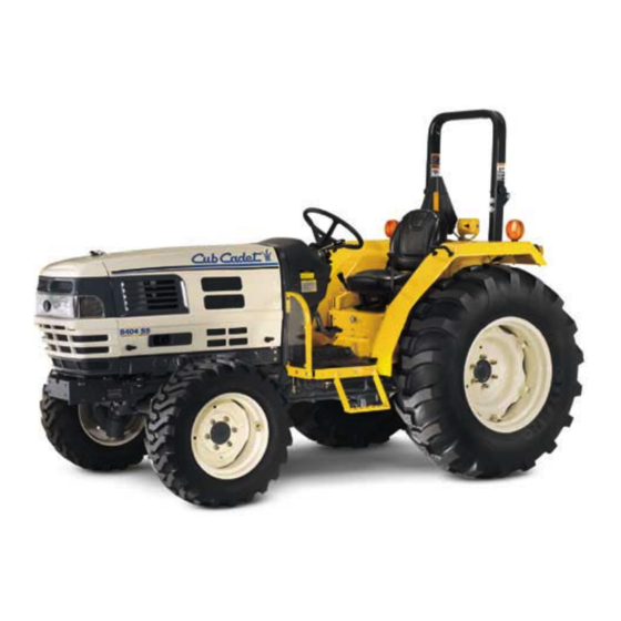
Cub Cadet 8354 Manuals
Manuals and User Guides for Cub Cadet 8354. We have
2
Cub Cadet 8354 manuals available for free PDF download: Service Manual, Operator's Manual
Cub Cadet 8354 Service Manual (289 pages)
Brand:
Cub Cadet
| Category:
Tractor
| Size: 13 MB
Table of Contents
Table of Contents
3
Chapter 1 General Information
9
Tractor View
11
Tightening Torque for Standard Bolts and Nuts
12
Tightening Torque
12
Specifications
14
Identification
16
Engine Number
16
Chassis Number of the Tractor(Chassis Number of the Machine)
16
Caution before Repair
17
Before Repair or Inspection
17
Assembly and Disassembly
17
Parts to be Replaced
17
Parts
17
Asbestos Parts
18
Electrical System
18
Tubes and Rubbers
19
Lubricant
19
Regular Check List
20
Oil & Water Supply List
21
Chapter 2 Engine System
23
General
25
Appearance
25
Specifications
26
Performance Curve
27
Dimensions
28
General Warning
28
Structure and Function
29
Body
29
Lubricating System
33
Cooling System
35
Fuel System
37
Disassembling and Servicing
45
Troubleshooting
45
Servicing Specifications
48
Checking, Disassembling and Servicing
55
Chapter 3 Clutch
89
Disassembly and Assembly
91
Disassembly of Panel Frame
91
Disassembly of Fender and Stepladder Assembly
94
Clutch
96
Characteristics
96
Link Structure and Control
97
Troubleshooting
98
Specification
99
Tightening Torque
99
Disassembly, Maintenance
100
Chapter 4 Transmission
105
Structure
107
Power Transmission
108
Main Transmission
108
Shuttle
111
Hi-Lo Shift
112
MID Pto
113
Rear Pto
113
Creeper Speed (if Applicable )
114
Front Wheel Drive
114
Transmission Shift Link Structure
115
Main Shift
115
Shuttle Shift
115
Hi-Lo Shift
116
Creeper Speed
116
MID Pto Shift
117
Front Wheel Drive Shift
117
Pto Clutch
118
Characteristics
118
Hydraulic Circuit
118
Oil Flow
119
Differential Gear
120
Structure
120
Operation
121
Troubleshooting
123
Maintenance Specification
124
Tightening Torque
125
Clutch Housing
126
Transmission Oil Draining
127
Clutch Housing Group Disassembly
127
Clutch Housing Disassembly
132
First Stage (Disconnection of Main Transmission Cover)
132
Second Stage (Disconnection of Propulsion Shaft Case)
133
Third Stage (Disassembly of 25 Gear Shaft and Propulsion Shaft 1)
134
Fourth Stage (Disassembly of Bearing Cover Assembly)
134
Fifth Stage (Disconnection of Transmission Fork)
135
Sixth Stage (Disassembly of 22 Gear Shaft)
136
Seventh Stage (Disassembly of Main Transmission Counter Shaft)
137
Maintenance
139
Intermediate Case
141
Disassembly, Assembly
142
Maintenance
147
Transmission Case
150
Disassembly, Assembly
150
Maintenance
160
Chapter 5 Rear Axle
165
Structure
167
Tightening Torque
168
Service Specification
169
Disassembly, Assembly
170
Disconnection of Rear Axle Group
170
Disassembly of Rear Axle
172
Maintenance
173
Bearing Check
173
Gear Check
173
Clearance Check of Planetary Gear and Planetary Gear Shaft
173
Check Thrust Collar for Worn
173
Chapter 6 Brake
175
Structure
177
Operation
178
Troubleshooting
179
Maintenance Specification
180
Tightening Torque
180
Brake Pedal
181
Disassembly, Maintenance
181
Maintenance
182
Brake Case
183
Disassembly and Assembly
183
Operation Check of Brake Cam Lever
186
Chapter 7 Front Axle
189
Structure
191
Wheel Alignment
192
Troubleshooting
193
Maintenance Specification
194
Tightening Torque
195
Disassembly, Maintenance
196
Disconnection of Front Axle Group
198
Disassembly, Assembly
198
Disassembly of Front Axle
200
First Stage (Disconnection of Front Axle Case and Bevel Gear Case)
200
Second Stage (Disassembly of Front Axle)
200
Third Stage (Disassembly of Front Axle Case)
201
Fourth Stage (Disassembly of Front Axle Support)
202
Fifth Stage (Disassembly of Front Axle Support)
203
Sixth Stage (Disassembly of Bevel Pinion Shaft)
204
Seventh Stage (Disassembly of Differential Gear)
205
Maintenance
206
Clearance Check between Center Pin, Front Axle Support Boss and
206
Front and Real Brackets
206
Check for Backlash and Tooth Contacted in Front Axle Case
206
Check for Bevel Gear Backlash and Tooth Contacted in Bevel Gear Case
207
Check for Shim between Axle Case Support and Front Axle Case
207
Check for Backlash and Tooth Contacted between Bevel Pinion Shaft
208
And Spiral Bevel Gear
208
Clearance Check between Differential Pinion Shaft and
209
Differential Pinion
209
Clearance Check between Front Differential Case, Differential Case Cover
209
And Differential Side Gear
209
Differential Side Gear
209
Chapter 8 Steering System
211
Characteristics
213
Hydraulic Circuit of Power Steering System
214
Gear Pump
215
Pump Characteristics
215
Major Specification
215
Structure of Gear Pump
215
Operation
216
Power Steering Unit
217
Major Spec
217
Structure and Operation
217
Steering Cylinder
218
Structure
218
Major Specification
218
Oil Flow
219
In Neutral
219
Turning to the Right
219
Turning to the Left
220
Manual Steering
220
Troubleshooting
221
Disassembly, Maintenance
222
Gear Pump
222
Power Steering Unit
224
Steering Cylinder
231
Chapter 9 Hydraulic System
235
Hydraulic Circuit Diagram
237
Structure
238
Hydraulic Circuit Diagram of 3-Point Hydraulic System
239
Hydraulic Pump
240
Structure of Hydraulic Pump
240
Operation
240
Oil Filter
241
Structure of Oil Filter
241
Function and Operation
241
Control Valve (Mls Valve)
242
Structure
242
Circuit Diagram
242
Operation Principle
243
Relief Valve (Hydraulic Block)
246
Hydraulic Cylinder
247
Structure and Operation
248
Structure
248
Operation
249
Outside Hydraulic Extraction
252
Hydraulic Block
252
Acting Valve
253
Quick Coupler
253
Top Link Bracket Device
254
Structure
254
Operation
254
Troubleshooting
255
Maintenance Specification
256
3-Point System Hydraulic Pump
256
Relief Valve
256
Link Control
256
Hydraulic Cylinder
257
Tightening Torque
258
Disassembly, Assembly
259
Gear Pump
259
Maintenance
261
Relief Valve
261
Hydraulic Cylinder
262
Check and Adjustment
268
Chapter 10 Electric System
273
Electronic Instrumentation
275
Instrument Gauge
275
Indicators and Warning Lights
276
Trouble Shooting
278
Servicing Specifications
280
Mechanism
281
Starting System
281
Operation of Start Motor
282
Charging System
284
Preheating System
286
Fuse
287
Gauge and Sensors
288
Main Circuit Diagram
289
Advertisement
Cub Cadet 8354 Operator's Manual (56 pages)
Cub Cadet Compact Tractor Operator's Manual 8000 Series
Brand:
Cub Cadet
| Category:
Tractor
| Size: 1 MB
Table of Contents
Table of Contents
2
To the Owner
2
Calling Service Information
2
Recording Model and Serial Number Information
3
General Operation
4
Important Safe Operation Practices
4
Slope Operation
7
Operating the Pto
8
Safety Frame (Rops)
8
Your Responsibility
9
Safety Labels
10
Section 1: Controls and Features
12
Tachometer Hourmeter
15
Section 2: Operation
20
Starting the Engine
21
Stopping the Engine
22
Driving the Tractor
22
Stopping the Tractor
23
Driving on Slopes
24
Check While Operating
25
Travel Speeds
25
Using the Differential Lock
26
Differential Lock Pedal
26
Tractor Weighting
29
Section 3: Adjustments
30
Adjusting the Fan Belt Tension
31
Brake Adjustment
31
Clutch Adjustment
31
Lubrication Table
34
Section 4: Maintenance
34
Lubrication and Maintenance Chart
35
Accessing the Engine Compartment
36
Fuel System
36
Engine Oil and Oil Filter
38
Servicing the Air Cleaner
42
Servicing the Cooling System
43
Lubricating the Tractor
44
Servicing the Battery
46
Tire Maintenance
48
Tractor Storage
49
Engine Troubleshooting
50
Section 5: Troubleshooting
50
Tractor Troubleshooting
52
Battery Troubleshooting
53
Section 6: Specifications
54
Specifications
55
Items Not Covered
56
How to Obtain Service
56
Warranty
56
Advertisement
Related Products
Cub Cadet 8404
Cub Cadet 8454
Cub Cadet 882
Cub Cadet 805
Cub Cadet 833E Series
Cub Cadet 833R Series
Cub Cadet Sportsman Forest 800
Cub Cadet 898C
Cub Cadet 850 SWE
Cub Cadet 826 4x4
Cub Cadet Categories
Lawn Mower
Tractor
Snow Blower
Trimmer
Utility Vehicle
More Cub Cadet Manuals
Login
Sign In
OR
Sign in with Facebook
Sign in with Google
Upload manual
Upload from disk
Upload from URL