Sign In
Upload
Manuals
Brands
Canon Manuals
All in One Printer
mf6600 Series
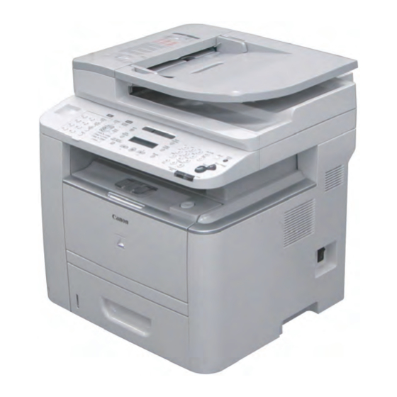
Canon mf6600 Series Manuals
Manuals and User Guides for Canon mf6600 Series. We have
1
Canon mf6600 Series manual available for free PDF download: Service Manual
Canon mf6600 Series Service Manual (227 pages)
Brand:
Canon
| Category:
All in One Printer
| Size: 19.26 MB
Table of Contents
Table of Contents
4
Safety Precautions
12
CDRH Provisions
13
Laser Safety
13
About Laser Beams
13
Handling Laser Scanner Unit
13
Toner Safety
14
About Toner
14
Handling Adhered Toner
14
Notes When Handling a Battery
14
Notes on Assembly/Disassembly
14
Product Overview
15
Product Lineups
15
Main Unit
16
Options
17
Product Features
17
Features
17
Compact MFP
17
High-Speed MFP
17
Power-Saving MFP
17
Specifications
18
Main Unit Specifications
18
ADF Specifications
19
FAX Specifications
19
Print Speed
20
Paper Types
20
Paper Size
21
Name of Parts
21
External View
21
Front Side
21
Rear Side
22
Cross Sectional View
23
Adf/Reader Unit
23
Printer
23
Operation Panel
24
Main Operation Panel
24
Send Operation Panel
24
Function List
25
BDL Print Area
25
Copy Area
25
PCL Print Area
25
Reception Print Area
25
Operation Environment of the Printer Driver
25
Hardware Environment
25
Network Specifications
25
Operation Environment
25
SEND Specifications
26
Technical Overview
27
Basic Configuration
27
Configuration Function
28
Basic Sequence
28
Basic Operational Sequence
28
Print Sequence
29
Print Mode
30
Document Exposure/Feeder System
31
Document Exposure System
31
Major Components
31
Specifications / Control / Function List
31
Document Feeder System
32
Pickup/Feed/Delivery Operation
32
Original Detection
33
Jam Detection
34
Service Tasks
34
Action for Parts Replacement
34
Maintenance
34
Service Notes
34
Engine Control System
35
Outline
35
Controls
35
Motor Control
36
Fan Control
37
Failure Detection
37
Low-Voltage Power Supply
38
Outline
38
Protective Function
39
Safety
39
Low-Voltage Power Supply Unit Failure Detection
39
Power-Saving Mode
39
Service Tasks
40
Action for Parts Replacement
40
Maintenance
40
Service Notes
40
Laser Scanner System
41
Outline
41
Optical Unit Failure Detection
41
Service Tasks
41
Action for Parts Replacement
41
Maintenance
41
Service Notes
41
Image-Formation System
42
Outline
42
Image-Formation Process
42
Developing Block
42
Latent Image Formation Block
42
Drum Cleaning Block
44
Fixing Block
44
Transfer Block
44
High-Voltage Power Supply
45
Outline
45
Service Tasks
45
Action for Parts Replacement
45
Maintenance
45
Notes on Field Service
45
Fixing Unit System
46
Outline
46
Fixing Control Circuit
47
Throughput Reduction Control
47
Fixing Temperature Control
48
Failure Detection
49
Protective Function
49
At Parts Replacement
50
Maintenance
50
Notes on Service Works
50
Service Tasks
50
Media Feed System
51
Drive Configuration
51
Outline
51
Jam Detection
52
Outline
52
Delivery Delay Jam
53
Delivery Stationary Jam
53
Door Open Jam
53
Fixing Paper Wrap Jam
53
Internal Residual Jam
53
Pickup Delay Jam
53
Pickup Stationary Jam
53
Reverse Delay Jam
53
Reverse Stationary Jam
53
Service Tasks
53
Periodical Services
54
Periodically Replaced Parts
55
Consumables Expected Replacement Timing
55
Consumable Parts
55
Durables Replaced by the User
55
Durables Replaced by the Service Person
55
Periodical Service
55
Cleaning
55
Cleaning at Service Visit
55
Cleaning Method (ADF)
56
Cleaning Method (External Covers)
56
Cleaning Method (Scanning Area)
56
Fixing Unit
57
Disassembly/Assembly
58
Preface
59
Outline
59
List of Parts
60
External View
60
Front Side
60
Rear Side
61
Main Unit
62
Main Parts
63
Sensor / Switc
63
Motor / Fan
64
Other
65
Pcb
66
Connector Layout Drawing (TAYPE
67
Internal
67
Connector Layout Drawing (TAYPE
71
Internal
71
External Cover, Internal Cover
75
External View
75
Front Side
75
Rear Side
76
Removing the Left Cover
76
Procedure
76
Removing the Left Rear Cover
79
Preparations
79
Procedure
79
Removing the Right Cover
80
Procedure
80
Removing the Right Rear Cover
83
Preparations
83
Procedure
83
Removing the Front Cover
83
Removing the Rear Cover Unit
84
Preparations
84
Procedure
84
Removing the Upper Cover Unit
85
Preparations
85
Procedure
85
Document Exposure, Feed System
87
Location
87
Removing the ADF Unit
87
Procedure
87
Removing the ADF Unit + Reader Unit
90
Preparations
90
Procedure
90
Separating the ADF Unit + Reader Unit
92
Preparations
92
Procedure
92
Removing the ADF Roller Unit
94
Procedure
94
Removing the ADF Pickup Roller
95
Preparations
95
Procedure
95
Removing the ADF Separation Roller
96
Preparations
96
Procedure
96
Removing the ADF Separation Pad
98
Procedure
98
Removing the ADF Pickup Feed Unit
99
Procedure
99
Removing the ADF Pickup Motor Unit
102
Preparations
102
Procedure
102
Removing the ADF Delivery Solenoid Unit
103
Preparations
103
Procedure
103
Removing the Reader Unit Upper Cover
103
Removing the CIS Unit
105
Preparations
105
Procedure
105
Removing the Reader Motor Unit
108
Preparations
108
Procedure
108
Controller System
110
Location1
110
Location2
111
Removing the Controller Cover
112
Preparations
112
Procedure
112
Removing the Adf/Reader Driver PCB
112
Preparations
113
Removing the NCU PCB
115
Preparations
115
Procedure
115
Removing the Capacitor PCB
116
Preparations
116
Procedure
116
Removing the All-Night Power PCB Mount (TYPE
116
Removing the All-Night Power PCB (TYPE
117
Preparations
117
Procedure
117
Removing the Power PCB (TYPE
117
Removing the Controller Box (TYPE
118
Preparations
118
Procedure
118
Removing the Engine Controller Unit (TYPE
121
Preparations
121
Procedure
121
Removing the Control Panel
127
Removing the Main Motor (TYPE
128
Preparations
128
Procedure
128
Removing the Main Motor (TYPE
130
Preparations
130
Procedure
130
Removing the Main Fan
132
Preparations
132
Procedure
132
Removing the Power Cooling Fan
132
Removing the Controller Fan (TYPE
134
Preparations
134
Procedure
134
Removing the Main Drive Unit (TYPE
134
Removing the Main Drive Unit (TYPE
138
Preparations
138
Procedure
138
Removing the Duplex Drive Unit (TYPE
141
Preparations
141
Procedure
141
Removing the Duplex Drive Unit (TYPE
143
Preparations
143
Procedure
143
Removing the Manual Tray Pickup Solenoid (TYPE
145
Preparations
145
Procedure
145
Removing the Manual Tray Pickup Solenoid (TYPE
146
Preparations
146
Procedure
146
Removing the Duplex Reverse Solenoid
147
Preparations
147
Procedure
147
Removing the Cassette Pickup Solenoid
147
Removing the Speaker (TYPE
148
Preparations
148
Procedure
148
Removing the Speaker (TYPE
149
Preparations
149
Procedure
149
Laser Exposure System
150
Location
150
Removing the Laser Scanner Unit
150
Preparations
150
Procedure
150
Image Forming System
152
Location
152
Removing the Transfer Roller
152
Removing the Registration Unit
153
Preparations (TYPE
153
Procedure
153
Fixing System
155
Location
155
Removing the Fixing Unit
155
Preparations
155
Procedure (TYPE
155
Procedure (TYPE II)
161
Paper Feed/Transport/Output System
161
Location
161
Preparations
161
Procedure
161
Removing the Duplex Feed Unit
161
Removing the Cassette Pickup Roller
163
Removing the Cassette Separation Pad
164
Removing the Multi-Purpose Pickup Roller
165
Removing the Multi-Purpose Separation Pad
165
Adjustment
167
Scanning System Adjustment
167
Procedure after Replacing the Reader Scanner Unit (the Contact Sensor)
168
Procedure after Replacing the Copyboard Glass
168
Procedure after Replacing the Reader Unit
168
Procedure after Replacing the ADF Unit
168
Electrical Adjustment
169
Procedure after Replacing the Main Controller Board
169
Trouble Shooting
170
Test Print
170
Engine-Test Page
171
Controller Test Print
171
Trouble Shooting Items
172
Image Defects
172
Dark Print
172
Light Print
172
All Black
173
Completely Blank
173
White Spots
173
Dirt on Back
174
Horizontal Lines
174
Vertical Lines
174
Dirt on Front
175
Dropouts
175
Vertical White Lines
175
Horizontal White Lines
176
Loose Toner
176
Misformed Image
177
Repetitive Image Defects Ruler
177
Adjustment of Fixing System
177
Nip-Width Specifications
177
Version
178
Overview
178
Overview of Upgrading
178
Preparation
178
Necessary System Environment
178
Before Downloading the System Software
179
Downloading the System Software
179
Downloading the System
179
Error Codes
182
Error Code
183
Fax Error Code
185
Outline
185
Error Code Outline
185
User Error Code
185
Service Error Code
186
Service Mode
188
Outline
188
Outline of Service Mode
189
Using the Mode
190
Default Settings
190
Service Mode Menus
190
Service Soft Switch Settings (SSSW)
194
Outline
194
Bit Switch Composition
194
Sssw-Sw01
194
Detailed Discussions of Bit
194
List of Functions
194
Sssw-Sw03
194
Detailed Discussions of Bit
195
Sssw-Sw04
195
List of Functions
195
Detailed Discussions of Bit 1
196
Sssw-Sw30
199
Menu Switch Settings (Menu)
200
Menu Switch Composition
200
No.005 NL Equalizer
200
No.006 Telephone Line Monitor
200
No.007 ATT Transmission Level
200
No.008 V.34 Modulation Speed Upper Limit
200
No.009 V.34 Data Speed Upper Limit
200
No.010 Frequency of the Pseudo CI Signal
200
Numeric Parameter Settings (Numeric Param.)
201
Numerical Parameter Composition
201
002: RTN Transmission Condition (1)><003: RTN Transmission Condition (2)><004: RTN Transmission Condition (3)
201
005: NCC Pause Length (Pre-ID Code)
201
006: NCC Pause Length (Post-ID Code)
202
010: Line Connection Identification Length
202
011: T.30 T1 Timer (for Reception)
202
013: T.30 EOL Timer
202
016: Time Length to First Response at Time of Fax/Tel Switchover
202
017: Pseudo RBT Signal Pattern on Time Length><018: Pseudo RBT Signal Pattern off Time Length (Short)><019: Pseudo RBT Signal Pattern off Time Length (Long)
202
020: Pseudo CI Signal Pattern on Time Length><021: Pseudo CI Signal Pattern off Time Length (Short)><022: Pseudo CI Signal Pattern off Time Length (Long)
202
023: CNG Detention Level for Fax/Tel Switchover
202
024: Pseudo RBT Transmission Level at Time of Fax/Tel Switchover
202
025: Answering Machine Connection Function Signal Detection Time
203
027: V.21 Low-Speed Flag Preamble Identification Length
203
<056 - 061: Count Type Select
203
Scanner Function Settings (Scanner)
206
Numeric Parameter Functional Configuration
206
031Vertical Scan Start Position Adjustment
206
033Vertical Scan Magnification Correction
206
<035: - 036:Reader Motor Speed Change
207
041: Vertical Scan Start Position Adjustment (When Scanning on a Document Fed from ADF)
207
047: Vertical Scan Magnification Correction (When Scanning on a Document Fed from ADF)
207
048: Horizontal Scan Magnification Correction (When Scanning on a Document Fed from ADF)
207
Printer Function Settings (Printer)
207
Service Soft Switch Settings (SSSW)
207
Sssw-Sw15
207
Numeric Parameter Settings (NUMERIC Param.)
207
035: Left-End Registration Adjustment (Cassette)
207
039: Left-End Registration Adjustment (Duplex Unit)
208
053: Margin Adjustment at the Leading Edge of the Copy
208
054: Margin Adjustment at the Trailing Edge of the Copy
208
055: Margin Adjustment at the Right Edge of the Copy
208
056: Margin Adjustment at the Left Edge of the Copy
208
Setting of System Functions (System)
208
Bit Switch Settings
208
Counter Indication (Counter)
209
Counters
209
Clearing Counters
209
Report Output (Report)
209
Report Output
209
System Data List
210
System Dump List
210
Counter List
211
Spec List
212
Data Initialization Mode (Clear)
213
Clear
213
Rom Management (Rom)
213
ROM Display
213
Test Mode (Test)
213
Outline
213
Overview
213
D-RAM Test<(1) D-RAM TEST
215
DRAM Test
215
Print Test
216
Print Test ((3) PRINT TEST)
216
Scan Test
216
Scan Test ((2) SCAN TEST)
216
Modem Test
217
Modem Test ((4) MODEM TEST)
217
Faculty Test
219
Function Test <(6) FUNCTION TEST
219
Cleaning Mode
222
Roller Cleaning Mode ((0) ROLLER CLEAN)
222
Appendex
223
Service Tools
224
Solvents and Oil List
224
General Timing Chart
225
General Circuit Diagram
226
General Circuit Diagram (TYPE I)
226
General Circuit Diagram (TYPE II)
227
Advertisement
Advertisement
Related Products
Canon imageCLASS MF6540PL
Canon imageCLASS MF6560PL
Canon imageCLASS Mf6160dw
Canon MF6150dw
Canon MF635Cx Series
Canon Color imageCLASS MF644Cdw
Canon Color imageCLASS MF642Cdw
Canon Color imageCLASS MF641Cw
Canon MF635C Series
Canon MF657Cdw
Canon Categories
Printer
Digital Camera
All in One Printer
Camcorder
Scanner
More Canon Manuals
Login
Sign In
OR
Sign in with Facebook
Sign in with Google
Upload manual
Upload from disk
Upload from URL