Sign In
Upload
Manuals
Brands
ABB Manuals
Protection Device
RELION RER670
ABB RELION RER670 Manuals
Manuals and User Guides for ABB RELION RER670. We have
6
ABB RELION RER670 manuals available for free PDF download: Applications Manual, Commissioning Manual, Installation Manual, Communication Protocol Manual
ABB RELION RER670 Applications Manual (506 pages)
Relion 670 Series, Railway application
Brand:
ABB
| Category:
Protection Device
| Size: 9.89 MB
Table of Contents
Table of Contents
7
Section 1 Introduction
23
This Manual
23
Intended Audience
23
Product Documentation
24
Product Documentation Set
24
Document Revision History
25
Related Documents
26
Document Symbols and Conventions
26
Symbols
26
Document Conventions
27
IEC 61850 Edition 1 / Edition 2 Mapping
28
Section 2 Application
31
General IED Application
31
Main Protection Functions
32
Back-Up Protection Functions
33
Control and Monitoring Functions
34
Communication
39
Basic IED Functions
41
Section 3 Configuration
43
Description of Configuration RER670
43
Introduction
43
Description of Configuration - Transformer Protection Application in Compensated Networks
44
Description of Configuration - Transformer Protection Application in Solidly Earthed Networks
45
Description of Configuration - Line Protection Application in Compensated Networks
46
Description of Configuration - Line Protection Application in Solidly Earthed Networks
47
Section 4 Analog Inputs
49
Introduction
49
Setting Guidelines
49
Setting of the Phase Reference Channel
50
Example
50
Setting of Current Channels
50
Example 1
51
Example 2
51
Example 3
52
Examples on How to Connect, Configure and Set CT Inputs for most Commonly Used CT Connections
54
Example on How to Connect a Star Connected Two-Phase CT Set to the IED
56
Example How to Connect Single-Phase CT to the IED
59
Relationships between Setting Parameter Base Current, CT Rated Primary Current and Minimum Pickup of a Protection IED
60
Example
61
Examples How to Connect, Configure and Set VT Inputs for most Commonly Used VT Connections
61
Setting of Voltage Channels
61
Examples on How to Connect a Two Phase-To-Earth Connected VT to the IED
62
Example on How to Connect a Residually Connected IED
64
Example of Analogue Configuration for Railway Applications
65
Configuration Example 1
66
Configuration Example 2
67
Configuration Example 3
68
Section 5 Local HMI
71
Display
72
Leds
74
Keypad
75
Local HMI Functionality
77
Protection and Alarm Indication
77
Parameter Management
78
Front Communication
79
Section 6 Differential Protection
81
Low Impedance Restricted Earth Fault Protection REFPDIF
81
Identification
81
Application
81
Transformer Winding, Solidly Earthed
82
CT Earthing Direction
83
Railway Specific Applications for REFPDIF Function
83
Setting and Configuration
83
Setting Guidelines
83
Settings
84
Single-Phase Railway Power Transformer Differential Protection T1PPDIF
84
Application
84
Identification
84
Restrained and Unrestrained Differential Protection
85
Setting Guidelines
85
Elimination of Zero Sequence Currents
88
Inrush Restraint Methods
88
Overexcitation Restraint Method
88
Protections Based on the Directional Criterion
89
Setting Examples
89
Application Examples
91
How to Wire the Transformer Differential Protection to the IED Using Cts
96
Section 7 Impedance Protection
101
Automatic Switch Onto Fault Logic ZCVPSOF
101
Identification
101
Application
101
Setting Guidelines
102
Distance Protection, Quadrilateral Characteristic ZRWPDIS
103
Identification
103
Application
103
Compensated Earthing Systems
104
Solidly Earthed Systems
119
High Impedance Earthing Systems
130
Setting Examples
141
Compensated Earthed Systems
141
Solidly Earthed Systems
149
Underimpedance Protection for Railway Transformers ZGTPDIS
156
Identification
156
Application
156
Zone 1 Operation
158
Zone 2 Operation
158
Zone 3 Operation
158
Setting Guidelines
158
Catenary Protection
160
Wrong Phase Coupling Protection
161
Section 8 Current Protection
163
Instantaneous Phase Overcurrent Protection 2-Phase Output PHPIOC
163
Identification
163
Application
163
Setting Guidelines
164
Meshed Network Without Parallel Line
164
Two-Step Directional Phase Overcurrent Protection D2PTOC
166
Identification
166
Application
166
Setting Guidelines
167
Settings for Step 1
170
Settings for Step 2
172
Instantaneous Residual Overcurrent Protection EFRWPIOC
172
Identification
172
Application
173
Setting Guidelines
173
Two Step Residual Overcurrent Protection EF2PTOC
175
Application
175
Identification
175
Setting Guidelines
176
Settings for each Step (X = 1 and 2)
177
Common Settings
178
2Nd Harmonic Restrain
179
Sensitive Directional Residual Overcurrent and Power Protection SDEPSDE
180
Application
180
Identification
180
Setting Guidelines
182
Thermal Overload Protection, One Time Constant, Celsius LPTTR
190
Application
190
Identification
190
Setting Guideline
192
Breaker Failure Protection CCRWRBRF
193
Application
193
Setting Guidelines
194
Overcurrent Protection with Binary Release BRPTOC
196
Identification
196
Application
197
Setting Guidelines
197
Tank Overcurrent Protection TPPIOC
197
Identification
197
Application
198
Setting Guidelines
200
Section 9 Voltage Protection
201
Two Step Undervoltage Protection U2RWPTUV
201
Identification
201
Application
201
Setting Guidelines
202
Backup Protection for Power System Faults
202
Disconnected Equipment Detection
202
Power Supply Quality
202
Settings for Two Step Undervoltage Protection
202
Voltage Instability Mitigation
202
Two Step Overvoltage Protection O2RWPTOV
204
Identification
204
Application
204
Setting Guidelines
205
Equipment Protection, Transformers
205
Power Supply Quality
205
The Following Settings Can be Done for the Two Step Overvoltage Protection
205
Two Step Residual Overvoltage Protection ROV2PTOV
207
Identification
207
Application
207
Setting Guidelines
207
High Impedance Earthed Systems
208
Settings for Two Step Residual Overvoltage Protection
208
Solidly Earthed Systems
208
Section 10 Frequency Protection
211
Underfrequency Protection SAPTUF
211
Identification
211
Application
211
Setting Guidelines
211
Section 11 Secondary System Supervision
213
Current Circuit Supervision CCSSPVC
213
Identification
213
Application
213
Setting Guidelines
214
Fuse Failure Supervision FRWSPVC
214
Identification
214
Application
214
Setting Guidelines
215
Deltau and Deltai Detection
215
Dead Line Detection
216
Sudden Current and Voltage Change
216
Section 12 Control
217
Synchrocheck, Energizing Check, and Synchronizing SESRSYN
217
Identification
217
Application
217
Synchronizing
217
Synchrocheck
219
Energizing Check
221
External Fuse Failure
222
Application Examples
223
Single Circuit Breaker with Single Busbar
224
Setting Guidelines
224
Autoreclosing for Railway System SMBRREC
229
Identification
229
Application
229
Auto Reclosing Operation off and on
232
Start Auto Reclosing and Conditions for Start of a Reclosing Cycle
232
Start Auto Reclosing from Circuit Breaker Open Information
232
Auto Reclosing Reclaim Timer
233
Blocking of the Auto Recloser
233
Control of the Auto Reclosing Dead Time for Shot 1
233
Long Trip Signal
233
Maximum Number of Reclosing Shots
233
Lock-Out Initiation
234
Permanent Fault and Reclosing Unsuccessful Signal
234
Pulsing of the Circuit Breaker Closing Command and Counter
234
Transient Fault
234
Thermal Overload Protection Holding the Auto Recloser Back230
236
Setting Guidelines
236
Configuration
236
Auto Recloser Settings
240
Apparatus Control APC
243
Application
243
Bay Control QCBAY
247
Switch Controller SCSWI
248
Switches SXCBR/SXSWI
249
Proxy for Signals from Switching Device Via GOOSE XLNPROXY
250
Reservation Function (QCRSV and RESIN)
252
Interaction between Modules
254
Setting Guidelines
256
Bay Control (QCBAY)
257
Switch Controller (SCSWI)
257
Switch (SXCBR/SXSWI)
258
Bay Reserve (QCRSV)
259
Proxy for Signals from Switching Device Via GOOSE XLNPROXY
259
Reservation Input (RESIN)
260
Interlocking
260
Configuration Guidelines
261
Interlocking for Line Bay ABC_LINE
261
Application
261
Signals from Bypass Busbar
262
Signals from Bus-Coupler
263
Configuration Setting
265
Interlocking for Bus-Coupler Bay ABC_BC
266
Application
267
Configuration
267
Signals from All Feeders
267
Signals from Bus-Coupler
269
Configuration Setting
271
Interlocking for Transformer Bay AB_TRAFO
272
Application
272
Configuration Setting
273
Signals from Bus-Coupler
273
Interlocking for Bus-Section Breaker A1A2_BS
274
Application
274
Signals from All Feeders
274
Configuration Setting
277
Interlocking for Bus-Section Disconnector A1A2_DC
278
Application
278
Signals in Single Breaker Arrangement
278
Signals in Double-Breaker Arrangement
281
Signals in 1 1/2 Breaker Arrangement
284
Interlocking for Busbar Earthing Switch BB_ES
285
Application
285
Signals in Single Breaker Arrangement
285
Signals in Double-Breaker Arrangement
289
Signals in 1 1/2 Breaker Arrangement
290
Interlocking for Double CB Bay DB
291
Application
291
Configuration Setting
292
Interlocking for 1 1/2 CB BH
293
Application
293
Configuration Setting
293
Voltage Control
294
Application
294
Setting Guidelines
327
TR1ATCC or TR8ATCC General Settings
327
TR1ATCC or TR8ATCC Setting Group
328
TCMYLTC and TCLYLTC General Settings
337
Logic Rotating Switch for Function Selection and LHMI Presentation SLGAPC
338
Identification
338
Application
338
Setting Guidelines
338
Selector Mini Switch VSGAPC
339
Setting Guidelines
340
Setting Guidelines
341
Application
342
Application
343
Setting Guidelines
345
Transformer Energizing Control XENCPOW
346
Setting Guidelines
347
Setting Examples
348
Scheme Communication Logic for Distance or Overcurrent Protection ZCPSCH
349
Blocking Schemes
350
Permissive Schemes
351
Intertrip Scheme
353
Setting Guidelines
354
Permissive Overreaching Scheme
355
Application
356
Weak-End Infeed Logic
357
Current Reversal Logic
358
Application
359
Current Reversal and Weak-End Infeed Logic for Residual Overcurrent Protection ECRWPSCH
360
Weak-End Infeed Logic
361
Setting Guidelines
362
Weak-End Infeed
363
Tripping Logic SMPPTRC
365
Lock-Out
366
Blocking of the Function Block
368
Setting Guidelines
369
Logic for Group Alarm WRNCALH
370
Configurable Logic Blocks
371
Fixed Signal Function Block FXDSIGN
373
Boolean 16 to Integer Conversion B16I
374
Boolean to Integer Conversion with Logical Node Representation, 16 Bit BTIGAPC
375
Integer to Boolean 16 Conversion IB16
376
Identification
377
Representation ITBGAPC
378
Elapsed Time Integrator with Limit Transgression and Overflow Supervision TEIGAPC
379
Setting Guidelines
380
Setting Guidelines
381
Comparator for Real Inputs - REALCOMP
382
Setting Example
383
Measurement
385
Zero Clamping
387
Setting Guidelines
388
Setting Examples
391
Gas Medium Supervision SSIMG
394
Liquid Medium Supervision SSIML
395
Setting Guidelines
396
Breaker Monitoring SSCBR
397
Setting Guidelines
399
Setting Procedure on the IED
400
Event Function EVENT
401
Disturbance Report DRPRDRE
402
Setting Guidelines
403
Recording Times
406
Analog Input Signals
407
Consideration
408
Logical Signal Status Report BINSTATREP
409
Setting Guidelines
410
Setting Guidelines
411
Application
412
Setting Guidelines
413
Setting Example
414
Pulse-Counter Logic PCFCNT
417
Function for Energy Calculation and Demand Handling ETPMMTR
418
Setting Guidelines
419
Access Point
421
Redundant Communication
422
Application
423
Setting Guidelines
424
Merging Unit
425
Setting Guidelines
426
Communication Protocols
427
Setting Guidelines
429
Receiving Data
430
IEC/UCA 61850-9-2LE Communication Protocol
431
Setting Guidelines
433
Specific Settings Related to the IEC/UCA 61850-9-2LE Communication
434
Setting Examples for IEC/UCA 61850-9-2LE and Time Synchronization
439
IEC 61850 Quality Expander QUALEXP
444
LON Communication Protocol
445
MULTICMDRCV and MULTICMDSND
446
Identification
447
Setting Guidelines
448
IEC 60870-5-103 Communication Protocol
450
Design
451
Settings
453
Settings for RS485 and Optical Serial Communication
454
Settings from PCM600
455
Function and Information Types
457
DNP3 Communication Protocol
458
Binary Signal Transfer
459
Communication Hardware Solutions
460
Setting Guidelines
461
Authority Status ATHSTAT
465
Change Lock CHNGLCK
466
Denial of Service SCHLCCH/RCHLCCH
467
IED Identifiers TERMINALID
469
Measured Value Expander Block RANGE_XP
470
Application
471
Setting Guidelines
472
Application
473
Signal Matrix for Binary Outputs SMBO
474
Frequency Values
475
Test Mode Functionality TESTMODE
476
Setting Guidelines
477
System Time
478
Process Bus IEC/UCA 61850-9-2LE Synchronization
479
Current Transformer Requirements
481
Conditions
483
Fault Current
484
General Current Transformer Requirements
485
Restricted Earth Fault Protection (Low Impedance Differential)
486
Current Transformer Requirements for Cts According to Other Standards
489
Voltage Transformer Requirements
490
SNTP Server Requirements
491
IEC/UCA 61850-9-2LE Merging Unit Requirements
492
Advertisement
ABB RELION RER670 Commissioning Manual (216 pages)
RELION 670 SERIES, Railway application Version 2.2 IEC
Brand:
ABB
| Category:
Power distribution unit
| Size: 4.38 MB
Table of Contents
Table of Contents
7
Section 1 Introduction
15
This Manual
15
Intended Audience
15
Product Documentation
16
Product Documentation Set
16
Document Revision History
17
Related Documents
18
Document Symbols and Conventions
18
Symbols
18
Document Conventions
19
IEC 61850 Edition 1 / Edition 2 Mapping
20
Section 2 Safety Information
23
Symbols on the Product
23
Warnings
23
Caution Signs
25
Note Signs
25
Section 3 Available Functions
27
Main Protection Functions
27
Back-Up Protection Functions
28
Control and Monitoring Functions
29
Communication
35
Basic IED Functions
37
Section 4 Starting up
39
Factory and Site Acceptance Testing
39
Commissioning Checklist
39
Checking the Power Supply
40
Energizing the IED
40
Checking the IED Operation
40
IED Start-Up Sequence
41
Setting up Communication between PCM600 and the IED
41
Writing an Application Configuration to the IED
46
Checking CT Circuits
47
Checking VT Circuits
48
Using the RTXP Test Switch
48
Checking the Binary Input/Output Circuits
49
Binary Input Circuits
49
Checking Optical Connections
49
Section 5 Configuring the IED and Changing Settings
51
Overview
51
Configuring Analog CT Inputs
52
Supervision of Input/Output Modules
52
Section 6 Establishing Connection and Verifying the SPA/IEC Communication
55
Entering Settings
55
Entering SPA Settings
55
Entering IEC Settings
55
Verifying the Communication
56
Verifying SPA Communication
56
Verifying IEC Communication
56
Fiber Optic Loop
57
Optical Budget Calculation for Serial Communication with SPA/IEC
57
Section 7 Establishing Connection and Verifying the LON Communication
59
Communication Via the Rear Ports
59
LON Communication
59
The LON Protocol
60
Hardware and Software Modules
60
Optical Budget Calculation for Serial Communication with LON
61
Section 8 Establishing Connection and Verifying the IEC 61850 Communication
63
Overview
63
Setting the Station Communication
63
Verifying the Communication
64
Section 9 Testing IED Operation
65
Preparing for Test
65
Requirements
65
Preparing the IED to Verify Settings
67
Activating the Test Mode
68
Preparing the Connection to the Test Equipment
68
Connecting the Test Equipment to the IED
69
Releasing the Function to be Tested
70
Verifying Analog Primary and Secondary Measurement
71
Testing the Protection Functionality
72
Forcing of Binary Input/Output Signals for Testing
73
Forcing Concept
73
How to Enable Forcing
73
Enable Forcing by Using LHMI
73
Enable Forcing Using TESTMODE Function Block
74
How to Change Binary Input/Output Signals Using Forcing
74
Forcing by Using LHMI
74
Forcing by Using PCM600
76
How to Undo Forcing Changes and Return the IED to Normal Operation
77
Undo Forcing by Using LHMI
78
Undo Forcing by Using PCM600
78
Undo Forcing by Using TESTMODE Component
78
Section 10 Testing Functionality by Secondary Injection
81
Testing Disturbance Report
81
Introduction
81
Disturbance Report Settings
81
Disturbance Recorder (DR)
81
Event Recorder (ER) and Event List (EL)
82
Identifying the Function to Test in the Technical Reference Manual
83
Differential Protection
83
Restricted Earth Fault Protection, Low Impedance REFPDIF
83
Verifying the Settings
83
Completing the Test
84
Single-Phase Railway Power Transformer Differential Protection T1PPDIF
84
Verifying the Directional Sensitive Protection
85
Verifying the Directional Unrestrained Protection
85
Verifying the Restrained Protection
85
Verifying the Unrestrained Protection
85
Completing the Test
86
Verifying the Blocking Functionality
86
Verifying the Differential Alarm
86
Impedance Protection
86
Automatic Switch Onto Fault Logic ZCVPSOF
86
Activating ZCVPSOF Externally
86
Completing the Test
87
Initiating ZCVPSOF Automatically and Setting Mode to Impedance
87
Initiating ZCVPSOF Automatically and Setting Mode to Uilevel
87
Distance Protection Zone, Quadrilateral Characteristic ZRWPDIS
88
Verifying the Signals and Settings
88
Catenary Distance Protection ZRCPDIS
105
Completing the Test
105
Underimpedance Protection for Railway Transformers ZGTPDIS
107
Verifying the Signals and Settings
107
Completing the Test
110
Current Protection
111
Instantaneous Phase Overcurrent Protection 2-Phase Output PHPIOC
111
Completing the Test
111
Measuring the Operate Limit of Set Values
111
Two-Step Directional Phase Overcurrent Protection D2PTOC
111
Completing the Test
112
Verifying the Settings
112
Instantaneous Residual Overcurrent Protection EFRWPIOC
113
Completing the Test
113
Measuring the Operate Limit of Set Values
113
Two Step Residual Overcurrent Protection EF2PTOC
113
Directional Stage
113
Completing the Test
114
Two Step Non-Directional Earth Fault Protection
114
Sensitive Directional Residual Overcurrent and Power Protection SDEPSDE
114
Measuring the Operate and Time Limit for Set Values
114
Completing the Test
120
Thermal Overload Protection, One Time Constant, Celsius LPTTR
120
Measuring the Operate and Time Limit of Set Values
120
Completing the Test
121
Breaker Failure Protection CCRWRBRF
121
Checking the Phase Current Operate Value, IP
121
Checking the Re-Trip and Back-Up Times
121
Verifying the Back-Up Trip
122
Verifying the Re-Trip Mode
122
Verifying Instantaneous Back-Up Trip at CB Faulty Condition
123
Verifying the Case Functionmode = Contact
123
Verifying the Function Mode Current/Contact
123
Completing the Test
124
Overcurrent Protection with Binary Release BRPTOC
124
Measuring the Operate Limit of Set Values
124
Completing the Test
125
Tank Overcurrent Protection TPPIOC
125
Verifying the Signals and Settings
125
Completing the Test
126
Voltage Protection
126
Two Step Undervoltage Protection U2RWPTUV
126
Verifying the Settings
126
Completing the Test
127
Two Step Overvoltage Protection O2RWPTOV
127
Verifying the Settings
127
Completing the Test
128
Two Step Residual Overvoltage Protection ROV2PTOV
128
Verifying the Settings
128
Completing the Test
129
Frequency Protection
129
Underfrequency Protection SAPTUF
129
Verifying the Settings
129
Completing the Test
130
Secondary System Supervision
130
Current Circuit Supervision CCSSPVC
130
Verifying the Settings
130
Fuse Failure Supervision FRWSPVC
131
Checking that the Binary Inputs and Outputs Operate as Expected
131
Measuring the Operate Value for the Dead Line Detection Function
131
Checking the Operation of the Du/Dt and DI/Dt Based Function
132
Completing the Test
132
Voltage Based Delta Supervision DELVSPVC
132
Verifying the Signals and Settings
132
Completing the Test
133
Current Based Delta Supervision DELISPVC
134
Completing the Test
134
Verifying the Signals and Settings
134
Delta Supervision of Real Input DELSPVC
135
Completing the Test
135
Verifying the Signals and Settings
135
Control
135
Synchrocheck, Energizing Check, and Synchronizing
135
Sesrsyn
135
Testing the Synchronizing Function
136
Testing the Synchrocheck Functionality
137
Testing the Energizing Check
140
Completing the Test
141
Autoreclosing for Railway System SMBRREC
141
Preparation of the Verification
143
Switching the Auto Recloser to on and off
144
Verifying the Auto Recloser
144
Checking the Auto Reclosing Conditions
145
Completing the Test
147
Apparatus Control APC
147
Tap Changer Control and Supervision TCMYLTC, TCLYLTC
147
Secondary Test
149
Check the Activation of the Voltage Control Operation
150
Check the Normal Voltage Regulation Function
150
Check the Undervoltage Block Function
151
Check the Upper and Lower Busbar Voltage Limit
151
Check the Overcurrent Block Function
152
Single Transformer
152
Parallel Voltage Regulation
153
Completing the Test
158
Single Command, 16 Signals SINGLECMD
158
Interlocking
158
Transformer Energizing Control XENCPOW
158
Verifying the Signals and Settings
158
Completing the Test
159
Scheme Communication
159
Scheme Communication Logic for Distance or Overcurrent Protection ZCPSCH
159
Testing Permissive Overreaching
160
Testing Permissive Underreaching
160
Checking of Unblocking Logic
161
Completing the Test
161
Testing Blocking Scheme
161
Current Reversal and Weak-End Infeed Logic for Distance Protection 2-Phase ZCRWPSCH
161
Current Reversal Logic
162
Weak End Infeed Logic
162
Completing the Test
163
Scheme Communication Logic for Residual Overcurrent Protection ECPSCH
163
Testing the Directional Comparison Logic Function
164
Completing the Test
165
Current Reversal and Weak-End Infeed Logic for Residual Overcurrent Protection ECRWPSCH
165
Testing the Current Reversal Logic
166
Testing the Weak-End Infeed Logic
166
Completing the Test
168
Logic
168
Tripping Logic
168
Circuit Breaker Lockout
168
Test for Trip
168
Completing the Test
169
Monitoring
169
Gas Medium Supervision SSIMG
169
Completing the Test
170
Testing the Gas Medium Supervision for Pressure Alarm and Pressure Lockout Conditions
170
Testing the Gas Medium Supervision for Temperature Alarm and Temperature Lock out Conditions
170
Liquid Medium Supervision SSIML
171
Testing the Liquid Medium Supervision for Level Alarm and Level Lockout Conditions
171
Testing the Liquid Medium Supervision for Temperature Alarm and Temperature Lock out Conditions
171
Completing the Test
172
Breaker Monitoring SSCBR
172
Verifying the Settings
172
Completing the Test
174
Event Function EVENT
174
Limit Counter L4UFCNT
174
Completing the Test
175
Fault Locator RWRFLO
175
Verifying Signals and Settings
175
Completing the Test
180
Current Harmonic Monitoring CHMMHAN
180
Verifying the Signals and Settings
180
Completing the Test
181
Voltage Harmonic Monitoring VHMMHAN
182
Completing the Test
182
Verifying the Signals and Settings
182
Metering
183
Pulse-Counter Logic PCFCNT
183
Function for Energy Calculation and Demand Handling ETPMMTR
183
Verifying the Settings
183
Completing the Test
184
Station Communication
185
Multiple Command and Transmit MULTICMDRCV / MULTICMDSND
185
Remote Communication
185
Binary Signal Transfer
185
Basic IED Functions
186
Parameter Setting Group Handling SETGRPS
186
Verifying the Settings
186
Completing the Test
187
Exit Test Mode
187
ABB RELION RER670 Commissioning Manual (188 pages)
Brand:
ABB
| Category:
Industrial Electrical
| Size: 2.81 MB
Table of Contents
Table of Contents
7
Introduction
15
This Manual
15
Intended Audience
15
Product Documentation
16
Product Documentation Set
16
Document Revision History
17
Related Documents
18
Document Symbols and Conventions
18
Symbols
18
Document Conventions
19
IEC 61850 Edition 1 / Edition 2 Mapping
19
Safety Information
23
Symbols on the Product
23
Warnings
23
Caution Signs
24
Note Signs
25
Available Functions
27
Main Protection Functions
27
Back-Up Protection Functions
27
Control and Monitoring Functions
28
Communication
34
Basic IED Functions
36
Starting up
39
Factory and Site Acceptance Testing
39
Commissioning Checklist
39
Checking the Power Supply
39
Energizing the IED
40
Checking the IED Operation
40
IED Start-Up Sequence
40
Setting up Communication between PCM600 and the IED
41
Writing an Application Configuration to the IED
45
Checking CT Circuits
45
Checking VT Circuits
46
Using the RTXP Test Switch
46
Checking the Binary Input/Output Circuits
47
Binary Input Circuits
47
Checking Optical Connections
47
Configuring the IED and Changing Settings
49
Overview
49
Configuring Analog CT Inputs
49
Supervision of Input/Output Modules
50
Establishing Connection and Verifying the SPA/IEC Communication
51
Entering Settings
51
Entering SPA Settings
51
Entering IEC Settings
51
Verifying the Communication
51
Verifying SPA Communication
52
Verifying IEC Communication
52
Fiber Optic Loop
52
Optical Budget Calculation for Serial Communication with SPA/IEC
53
Establishing Connection and Verifying the LON Communication
55
Communication Via the Rear Ports
55
LON Communication
55
The LON Protocol
56
Hardware and Software Modules
56
Optical Budget Calculation for Serial Communication with LON
57
Establishing Connection and Verifying the IEC 61850 Communication
59
Overview
59
Setting the Station Communication
59
Verifying the Communication
59
Testing IED Operation
61
Preparing for Test
61
Requirements
61
Preparing the IED to Verify Settings
62
Activating the Test Mode
63
Preparing the Connection to the Test Equipment
63
Connecting the Test Equipment to the IED
64
Releasing the Function to be Tested
64
Verifying Analog Primary and Secondary Measurement
65
Testing the Protection Functionality
66
Forcing of Binary Input/Output Signals for Testing
66
Forcing Concept
66
How to Enable Forcing
67
Enable Forcing by Using LHMI
67
Enable Forcing Using TESTMODE Function Block
67
How to Change Binary Input/Output Signals Using Forcing
67
Forcing by Using LHMI
67
Forcing by Using PCM600
69
How to Undo Forcing Changes and Return the IED to Normal Operation
70
Undo Forcing by Using TESTMODE Component
71
Undo Forcing by Using LHMI
71
Undo Forcing by Using PCM600
71
Testing Functionality by Secondary Injection
73
Testing Disturbance Report
73
Introduction
73
Disturbance Report Settings
73
Disturbance Recorder (DR)
73
Event Recorder (ER) and Event List (EL)
74
Identifying the Function to Test in the Technical Reference Manual
74
Differential Protection
74
Restricted Earth Fault Protection, Low Impedance REFPDIF
74
Function Revision History
75
Verifying the Settings
75
Completing the Test
75
Single-Phase Railway Power Transformer Differential Protection T1PPDIF
75
Function Revision History
76
Verifying the Restrained Protection
76
Verifying the Unrestrained Protection
76
Verifying the Directional Unrestrained Protection
76
Verifying the Directional Sensitive Protection
77
Verifying the Differential Alarm
77
Verifying the Blocking Functionality
77
Completing the Test
77
Advertisement
ABB RELION RER670 Installation Manual (112 pages)
Brand:
ABB
| Category:
Power distribution unit
| Size: 4.88 MB
Table of Contents
Table of Contents
7
Section 1 Introduction
11
This Manual
11
Intended Audience
11
Product Documentation
12
Product Documentation Set
12
Document Revision History
13
Related Documents
14
Document Symbols and Conventions
16
Symbols
16
Document Conventions
16
Section 2 Safety Information
19
Symbols on the Product
19
Warnings
19
Caution Signs
21
Note Signs
22
Section 3 Environmental Aspects
23
Sustainable Development
23
Disposing of the IED
23
Section 4 Unpacking, Inspecting and Storing
25
Removing Transport Packaging
25
Inspecting the Product
25
Identifying the Product
25
Checking Delivery Items
25
Inspecting the IED
25
Returning an IED Damaged in Transit
26
Storing
26
Section 5 Mounting
27
Required Tools
27
Checking Environmental Conditions and Mounting Space
27
Mounting the IED
27
Flush Mounting
28
Overview
28
Mounting Procedure for Flush Mounting
29
19" Panel Rack Mounting
30
Overview
30
Mounting Procedure for 19" Panel Rack Mounting
31
Wall Mounting
32
Overview
32
Mounting Procedure for Wall Mounting
33
How to Reach the Rear Side of the IED
33
Side-By-Side 19" Rack Mounting
34
Overview
34
Mounting Procedure for Side-By-Side Rack Mounting
35
IED Mounted with a RHGS6 Case
35
Side-By-Side Flush Mounting
36
Overview
36
Mounting Procedure for Side-By-Side Flush Mounting
37
Mounting the Injection Unit REX060 (REG670 Only)
37
Mounting the Coupling Capacitor Unit REX061 and Shunt Resistor Unit REX062 (REG670 Only)
38
Coupling Capacitor Unit REX061
38
Shunt Resistor Unit REX062
39
Section 6 Connecting
41
Making the Electrical Connection
41
IED Connectors
41
Overview
41
Front Side Connectors
43
Rear Side Connectors
44
Connection Examples for High Impedance Differential Protection
55
Connecting to Protective Earth
57
Connecting the Power Supply Module
58
Connecting to CT and VT Circuits
58
Connecting the Binary Input and Output Signals
59
Making the Shield Connection
61
Making the Electrical Connection to the Rotor and Stator Injection Equipment (REG670 Only)
63
Connectors for Injection Unit REX060, Coupling Capacitor Unit REX061 and Shunt Resistor Unit REX062
63
Injection Unit REX060
63
Coupling Capacitor Unit REX061
66
Shunt Resistor Unit REX062
68
Connecting Injection Unit REX060, Coupling Capacitor Unit REX061 and Shunt Resistor Unit REX062
69
Connecting and Setting Voltage Inputs
75
Making of Ethernet Connections
77
Connecting Station Communication Interfaces
77
Connecting Remote Communication Interfaces LDCM
78
Installing the Serial Communication Cable for RS485
79
RS485 Serial Communication Module
79
Installing the Serial Communication Cable for RS485 SPA/IEC
83
Data on RS485 Serial Communication Module Cable
85
Installing the GPS Antenna
85
Antenna Installation
85
Electrical Installation
87
Lightning Protection
87
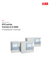
ABB RELION RER670 Installation Manual (102 pages)
Version 2.2 ANSI
Brand:
ABB
| Category:
Protection Device
| Size: 6.22 MB
Table of Contents
Table of Contents
7
Introduction
11
This Manual
11
Intended Audience
11
Section 1 Introduction
11
Product Documentation
12
Product Documentation Set
12
Document Revision History
13
Related Documents
13
Document Symbols and Conventions
15
Symbols
15
Document Conventions
16
Safety Information
17
Symbols on the Product
17
Warnings
17
Section 2 Safety Information
17
Caution Signs
18
Note Signs
19
Environmental Aspects
21
Sustainable Development
21
Disposing of the IED
21
Section 3 Environmental Aspects
21
Unpacking, Inspecting and Storing
23
Removing Transport Packaging
23
Inspecting the Product
23
Identifying the Product
23
Checking Delivery Items
23
Inspecting the IED
23
Returning an IED Damaged in Transit
23
Storing
24
Mounting
25
Required Tools
25
Checking Environmental Conditions and Mounting Space
25
Mounting the IED
25
Section 5 Mounting
25
Flush Mounting
26
Overview
26
Mounting Procedure for Flush Mounting
27
19" Panel Rack Mounting
27
Overview
27
Mounting Procedure for 19" Panel Rack Mounting
28
Wall Mounting
29
Overview
29
Mounting Procedure for Wall Mounting
29
How to Reach the Rear Side of the IED
29
Side-By-Side 19" Rack Mounting
30
Overview
30
Mounting Procedure for Side-By-Side Rack Mounting
31
IED Mounted with a RHGS6 Case
31
Side-By-Side Flush Mounting
32
Overview
32
Mounting Procedure for Side-By-Side Flush Mounting
33
Mounting the Injection Unit REX060 (REG670 Only)
33
Mounting the Coupling Capacitor Unit REX061 and Shunt Resistor Unit REX062 (REG670 Only)
34
Coupling Capacitor Unit REX061
34
Shunt Resistor Unit REX062
35
Connecting
37
Making the Electrical Connection
37
IED Connectors
37
Overview
37
Section 6 Connecting
37
Front Side Connectors
39
Rear Side Connectors
40
Connection Examples for High Impedance Differential Protection
51
Connecting to Protective Ground
53
Connecting the Power Supply Module
53
Connecting to CT and VT Circuits
54
Connecting the Binary Input and Output Signals
55
Making the Shield Connection
57
Making the Electrical Connection to the Rotor and Stator Injection Equipment (REG670 Only)
59
Connectors for Injection Unit REX060, Coupling Capacitor Unit REX061 and Shunt Resistor Unit REX062
59
Injection Unit REX060
59
Coupling Capacitor Unit REX061
61
Shunt Resistor Unit REX062
63
Connecting Injection Unit REX060, Coupling Capacitor Unit REX061 and Shunt Resistor Unit REX062
64
Connecting and Setting Voltage Inputs
69
Making of Ethernet Connections
71
Connecting Station Communication Interfaces
71
Connecting Remote Communication Interfaces LDCM
72
Installing the Serial Communication Cable for RS485
73
RS485 Serial Communication Module
73
Installing the Serial Communication Cable for RS485 SPA/IEC
76
Data on RS485 Serial Communication Module Cable
78
Installing the GPS Antenna
79
Antenna Installation
79
Electrical Installation
80
Lightning Protection
80
ABB RELION RER670 Communication Protocol Manual (48 pages)
Brand:
ABB
| Category:
Power distribution unit
| Size: 1.4 MB
Table of Contents
Table of Contents
7
Introduction
9
This Manual
9
Intended Audience
9
Product Documentation
9
Product Documentation Set
9
Document Revision History
10
Related Documents
11
Document Symbols and Conventions
12
Symbols
12
Document Conventions
13
SPA Application
15
SPA Communication Protocol
15
Application
15
Setting Guidelines
16
SPA Operation Principle
17
Operation Principle
17
Introduction of SPA Protocol
17
SPA Protocol
17
I/O Modules
18
Single Command, 16 Signals
18
Event Function EVENT
20
Connection of Signals as Events
21
Communication Ports
22
Design
22
SPA Settings
25
Settings
25
SPA Technical Data
27
Technical Data
27
Establishing Connection and Verifying the SPA/IEC Communication
29
Entering Settings
29
Entering SPA Settings
29
Verifying the Communication
29
Verifying SPA Communication
29
Fiber Optic Loop
30
Optical Budget Calculation for Serial Communication with SPA/IEC
30
SPA Functions
31
SPA, 670 Series Communication Protocol Manual
31
Event Function EVENT
31
Identification
31
Function Block
31
Signals
31
Settings
32
Operation Principle
34
Setting Guidelines
35
Eventmask (Ch_1 - 16)
35
Lonchannelmask or Spachannelmask
35
Minrepintval (1 - 16)
36
Logical Signal Status Report BINSTATREP
36
Identification
36
Advertisement
Related Products
ABB REF601
ABB REG650 ANSI
ABB REJ601
ABB Relion REG670
ABB RELION 650 SERIES
ABB RET650 2.2
ABB REF611
ABB RET615
ABB REM615 ANSI
ABB REM630
ABB Categories
Industrial Equipment
Controller
Measuring Instruments
Battery Charger
DC Drives
More ABB Manuals
Login
Sign In
OR
Sign in with Facebook
Sign in with Google
Upload manual
Upload from disk
Upload from URL