
Subscribe to Our Youtube Channel
Related Manuals for Clarke CWP1000A


Summary of Contents for Clarke CWP1000A
- Page 1 SUBMERSIBLE CLEAN WATER PUMP MODEL NO: CWP1000A PART NO: 7230097 OPERATION & MAINTENANCE INSTRUCTIONS LS0814...
-
Page 2: Environmental Recycling Policy
INTRODUCTION Thank you for purchasing this CLARKE Submersible Clean Water Pump. This pump is designed for pumping clean water only. It is NOT designed for pumping slurry, sludge, mud or heavily polluted water, or any water containing chemicals or other acidic contaminants including salt water. -
Page 3: Safety Instructions
SAFETY INSTRUCTIONS GENERAL PUMP SPECIFIC 1. Read all instructions before use 1. Do not pump explosive / and save these instructions for flammable liquids or chemicals. future use. 2. Never allow the pump to run dry 2. An approved residual current or operate out of the water. -
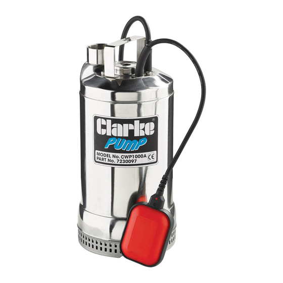
Page 4: Part Identification
PART IDENTIFICATION FLOAT SWITCH WATER OUTLET WATER INLET HANDLE PLUG AND CABLE Remove all packaging and make sure that the unit contains no visible damage. Dispose of all packaging appropriatly. Parts & Service: 020 8988 7400 / E-mail: Parts@clarkeinternational.com or Service@clarkeinternational.com... -
Page 5: Electrical Connections
ELECTRICAL CONNECTIONS WARNING: READ THESE ELECTRICAL SAFETY INSTRUCTIONS THOROUGHLY BEFORE CONNECTING THE PRODUCT TO THE MAINS SUPPLY. Connect the mains lead to a standard, 230 Volt (50Hz) electrical supply through an approved 13 amp BS 1363 plug, or a suitably fused isolator switch. If the plug has to be changed because it is not suitable for your socket, or because of damage, it must be removed and a replacement fitted, following the wiring instructions shown below. -
Page 6: Using The Pump
PUMP IF IT IS DAMAGED IN ANY WAY. 1. Connect a suitable hose (not supplied) to the pump outlet. • Suitable hoses are available from your local Clarke dealer. 2. Place the pump on a flat surface in the area that you want to drain. -
Page 7: Maintenance
IS UNPLUGGED FROM THE MAINS SUPPLY. IF THE UNIT IS HARD WIRED, ENSURE THE CIRCUIT BREAKER IS OPEN. This pump should require no maintenance other than regular cleaning. If the pump starts to show signs of wear or damage, contact your CLARKE dealer for advice. CLEANING 1. -
Page 8: Troubleshooting
7. Water level too low - float switch in OFF position - lift float to check switch. 8. If the pump still fails to start, consult your CLARKE dealer for advice. PUMP WILL 1. Check that the inlet is not blocked. -
Page 9: Declaration Of Conformity
DECLARATION OF CONFORMITY Parts & Service: 020 8988 7400 / E-mail: Parts@clarkeinternational.com or Service@clarkeinternational.com... -
Page 10: Parts List And Diagram
PARTS LIST & DIAGRAM Screw O Ring 29 Upper Motor Cover Strainer Footing Rotor 30 Cable Gland Bottom Caslng Cover Motor Frame Float Switch Bolt Stator 32 Power Cable Spring Washer Fluid Diffuser 33 Screw lmpeller Corrugated Sheet 34 Screw O Ring Screw 35 O Ring... - Page 11 ACCESSORIES Layflat Hoses Assorted Hose Clip Set - CHT672 • Available in 100 metre coils or per • 26 piece assorted hose clip set in meter. various sizes, Including. 8 x16mm, • Available in 1” - 3” Diameter. 6 x 22mm, 4 x 25mm, 2 x 28mm, 2 x 35mm &...
Need help?
Do you have a question about the CWP1000A and is the answer not in the manual?
Questions and answers