
Subscribe to Our Youtube Channel
Related Manuals for Clarke CU150


Summary of Contents for Clarke CU150
- Page 1 PETROL DRIVEN WATER PUMP Model CU150 Part No: 7140635 OPERATING & MAINTENANCE INSTRUCTIONS GC0410...
-
Page 2: Introduction
GUARANTEE This CLARKE product is guaranteed against faulty manufacture for a period of 12 months from the date of purchase. Please keep your receipt as proof of purchase. -
Page 3: Table Of Contents
& filters etc. Contact your CLARKE dealer for further information, or CLARKE International Sales Department on 01992 565333. IMPORTANT: The use of parts other than genuine CLARKE replacement parts may result in safety hazards, decreased tool performance, and will invalidate your warranty. -
Page 4: General Safety Precautions
GENERAL SAFETY PRECAUTIONS As with all machinery, there are certain hazards involved with its operation and use. Exercising caution will reduce the risk of personal injury. WORK AREA 1. ALWAYS keep the work area clean and well lit. Floors should always be kept clear. - Page 5 SERVICING 1. ALWAYS have the pump serviced by your local CLARKE dealer, using only identical replacement parts. This will ensure the safety of the pump is maintained. The use of non standard parts could be hazardous.
-
Page 6: Component Identification
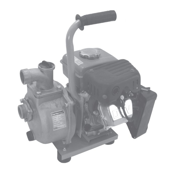
INTRODUCTION The CU150 Pump consists of a petrol (gasoline) engine and water pump which is fixed to the frame via a shock absorbing mounting. The self-priming pump consists of a pump body, cover, impeller and mechanical seal assembly. The inlet of the pump is higher than the inlet of the impeller so that it can start operating when only the body of the pump is filled with water. - Page 7 Fig 1 15 16 Fig 2...
-
Page 8: Preparation For Use
PREPARATION FOR USE INSTALLING THE HANDLE The handle must be bolted to the frame using two M8 x 12 bolts (item 2 - pages 20/21). Bolt the handle to the frame & tighten securely as shown in Fig 3. ADDING OIL Note: This pump is not supplied with engine oil. -
Page 9: Installation
INSTALLATION POSITIONING THE PUMP 1. Place the pump on a firm foundation and as near to the water source as possible. 2. Ensure there is adequate drainage for the discharged water, and that there is no danger of damage to property as a result of the pumping operation. -
Page 10: Operation
REMEMBER: Contaminated water is water containing small solids in suspension, do not pump slurry, sludge, sand, or mud. CONNECTING THE STRAINER 1. Attach the suction strainer to the end of suction hose using the third hose clamp (of the three supplied), to prevent stones etc, from being drawn up, which could cause severe damage to the pump. - Page 11 6. Once the engine starts, gradually return the choke to the left (RUN) position as the engine warms up, and use the engine throttle to gradually increase engine speed. 7. After starting the engine, move the throttle to the LEFT (open) position during priming of the pump and checking for pump output which is controlled by adjusting the engine speed.
-
Page 12: Maintenance
MAINTENANCE 1 Always maintain the pump in a clean condition, checking regularly for loose bolts etc. AIR FILTER 1. Clean the air filter once every 50 hours of use (or more often in unusually dusty conditions) as follows. Unscrew both the plastic wingnuts and lift out the cleaner element. - Page 13 CHANGING THE OIL The oil in the engine should be changed after the first 20 hours use and thereafter every 6 months or 100 running hours. 1. Remove the dipstick and drain plug and then gently tilt the machine to drain the oil into a suitable container.
-
Page 14: Technical Specification
Please note that the details and specifications contained herein, are correct at the time of going to print. However, CLARKE International reserve the right to change specifications at any time without prior notice. -
Page 15: Troubleshooting
TROUBLESHOOTING 1 (PUMP) l n I l n i l n I s l i v i l t i s t i s . r i l i f n i l . r i l n I l n i . - Page 16 TROUBLESHOOTING 2 (PUMP) s i s l n i y l l . s r t i s . r i n i l . r i l i f l l i . y l s r i n i l f - l l t t i .
- Page 17 TROUBLESHOOTING 3 (ENGINE) s l i l l i r t s t i s t i s t i s l l i t / r i s l i / r i n i l n i l .
- Page 18 TROUBLESHOOTING 4 (ENGINE) s i l n i l . r i t i l l l i f n i l . f f . r i . r i t r i . t r n I l .
-
Page 19: Parts Lists And Diagrams
PARTS LIST - ENGINE RECOIL STARTER & IGNITION ASSEMBLY ( t l o i t l i o ( t l ( t l l i o l i o e l f e l f... - Page 20 PARTS LIST - ENGINE FUEL SYSTEM t a l t e l i t a i t c l l u i t a t l o AIR CLEANER & MUFFLER ASSEMBLIES l f f CYLINDER HEAD ASSEMBLY ( t l i l y i l y i l y...
- Page 22 PARTS LIST - ENGINE CRANKSHAFT & PISTON ASSEMBLY p i l CRANKCASE ASSEMBLY i t s h t i i t a p i l t l o t i l i t a...
- Page 24 PARTS LIST - PUMP n i l t e l n i l l l e e l l p i l t e l t e l...
- Page 25 PARTS DIAGRAM - PUMP...
-
Page 26: Declaration Of Conformity
DECLARATION OF CONFORMITY... - Page 27 DECLARATION OF CONFORMITY...
Need help?
Do you have a question about the CU150 and is the answer not in the manual?
Questions and answers