Table of Contents
Advertisement
345 Bayview Avenue
Amityville, New York 11701
CALL TOLL FREE: 800-ALA-LOCK
(800) 252-5625
GENERAL DESCRIPTION
Models 265, 265L (long arm) and 715 are non-handed,
delayed egress, electronic exit door locking systems. Arming
is accomplished by actuating the deadbolt using a 1
cylinder (not included). When armed, depressing the paddle
(Model 265) or push bar (Model 715) will release the
deadbolt and sound an immediate alarm, however the
deadlatch will prevent the door from opening until the 15-
second exit delay has expired. Provisions are made for
instant alarmed exit in the event of actual emergencies, such
as smoke, fire, power failure, etc., using auxiliary detection
equipment.
A standard 9V alkaline battery is provided. This battery must
be installed at all times for proper operation of the unit. An
LED on the Control Box indicates that the unit is armed.
SPECIFICATIONS
Power: 12Vac, 20VA Transformer; 9Vdc Alkaline Battery
(Alarm Standby)
Current: 775mA max.; Alarm Circuit, Battery Only (Ac
Failure): Standby, 20µA typ.; Alarm, 75mA typ.
Standby: 1 year typ.
Battery Life: 200 alarm sequences typ. or constant alarm for
7 hours typ.
Latch Release Time: 13-15 seconds
Auto Alarm Shutdown: 2 minutes typ.
Sound Pressure Level: 95dB measured at 10 ft.
Operating Temperature: 20 to 135°F (-7 to 57°C)
Finish: US28 Aluminum or US312 Duronodic Powder Coat
Dimensions (hxwxd): Lock: Model 265, 8½"x18"x3¼";
Model 715, 8½"x33"x3¼"; Control Box: Model 265 or
Model 715, 5"x3½"x2"
Shipping Weight: Model 265, 11½ lbs; Model 715, 13½ lbs.
FEATURES
• 15-second delayed egress
• Meets NFPA101 Life Safety Code
• Local smoke-detector input (easy key reset)
• Selectable alarm: continuous or two-minute shutdown
• Exterior key control (requires additional rim cylinder)
• Audible low-battery indication
• Visual armed indicator LED (on Control Box)
• Piercing electronic siren (95dB at 10 feet)
• Full 1" throw deadbolt with rotating steel inserts.
EQUIPMENT SUPPLIED
• The following items are supplied with the product:
• Lock Assembly, with 9V alkaline backup battery
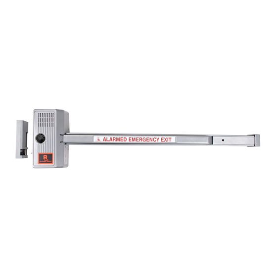
ELECTRONIC EXIT DOOR ALARMS
PADDLE ARM MODEL 265/265L
PUSH BAR MODEL 715
INSTALLATION AND OPERATION INSTRUCTIONS
• Single-Door Keeper Assembly
• Paddle-Arm Assembly (Model 265); or Push Bar
1
/
" rim
• Control Box Assembly
8
• Model 271 Flexible Conduit, with covers (2)
• Power Transformer
• 5-Conductor Cable (10 feet)
• Self-Adhesive Warning Labels (Model 265, 1; Model
OPTIONAL EQUIPMENT
• Available on special order: Option 88 Version - Remote
• Rim Cylinder, Model CER or equivalent (required)
• Surface Wiring Kit, Model SWK715
• Smoke Detector, 2-Wire. (Recommended: System
INSTALLATION
Preliminary Considerations
Important! To comply with National Fire Protection
Association Standard NFPA101, this lock must be connected
to an approved supervised automatic fire-detection system or
sprinkler system that will automatically unlatch the lock
instantly in the event of an emergency. See Connection to
Remote Life-Safety Equipment.
Models 265 and 715 are designed for use on doors equipped
with door checks to ensure that the door closes completely
and automatically. The Lock Assembly is mounted on a
single left- or right-handed reverse steel door. (These
instructions include information for mounting Model 715 onto
a narrow-stile glass door).
Fig. 1 Typical Installation, left-handed reverse door, inside view. If
snaking wires within door, see Note above.
Assembly (Model 715)
715, 2) required to comply with NFPA 101 Hardware
Interface and Alarm Indicator Relay
Sensor 1400, 2400, 2400TH; or 1451, 2451, 2451TH
with B401B Base)
P5708A 11/93
Mounting onto a solid door
1
Advertisement
Table of Contents

Subscribe to Our Youtube Channel
Related Manuals for Alarm Lock PUSH BAR 715


Summary of Contents for Alarm Lock PUSH BAR 715
- Page 1 ELECTRONIC EXIT DOOR ALARMS PADDLE ARM MODEL 265/265L PUSH BAR MODEL 715 345 Bayview Avenue INSTALLATION AND OPERATION INSTRUCTIONS Amityville, New York 11701 CALL TOLL FREE: 800-ALA-LOCK (800) 252-5625 P5708A 11/93 • Single-Door Keeper Assembly GENERAL DESCRIPTION Models 265, 265L (long arm) and 715 are non-handed, •...
- Page 2 requires an optional Surface Wiring Kit, Model SWK715, for Bolt Cover. Cut the rim cylinder tailpiece so that it extends routing of wires from the Lock Assembly to the Control Box. ” beyond the Rim Cylinder Housing. Facing the front of the lock, install the rim cylinder with the keyway horizontal.
- Page 3 washer from the Paddle Arm Hinge Bracket. Depress the 1. Insert the loose end of the Flexible Conduit into the ª hole Paddle Arm Hinge Bracket slightly and attach the Push in the Control Box and secure it with the retaining clip. Bar to the bracket using the #10-32 Phillips screw and 2.
- Page 4 momentarily when disarming. The LED on the control box will light when armed. Solenoid Position Adjustment A fine adjustment of the Solenoid may be required if its factory position has been disturbed. To check the position of the solenoid, apply power to the lock. With the Solenoid energized, check for approximately “...
- Page 5 EXPLODED VIEW AND PARTS LIST, MODEL 265 2. When the lock is disarmed, pressing the bar or paddle will the battery promptly. An alkaline replacement is strongly open the door instantly without sounding the alarm. Check recommended for optimum reliability and length of that the lock relatches after 5 seconds.
- Page 6 Ref. No. Description Part No. Ref. No. Description Part No. Keeper Cover P0248 Screw, 10-32x Allen P5191 Retaining Ring, Truarc P1140 Nut, 4-40x P1416 Pivot Arm P5093 Screw, 4-40x PH Phillips P5194 Keeper Base P5642 Insulator, Fish Paper P5651 Roller, Deadbolt P1158 Screw, 8-32x0.375 PH Phillips P5714...
- Page 7 EXPLODED VIEW AND PARTS LIST, MODEL 715 Ref. No. Description Part No. Ref. No. Description Part No. Push Bar P5010 Keeper Cover P0248 Screw, #10x1 FH Phillips P1676 Retaining Ring, Truarc P1140 Screw, #10x1 PH Phillips P1675 Pivot Arm P5093 Channel Insert P5046 Keeper Base...
- Page 8 Lever Subassembly (Ref. Nos. 111, 112, 113, 114) ..S5910 31, 32, 44, 53, 54, 115, 125, 126, 134) ...... S5908 Deadbolt Subassembly (Ref. Nos. 7, 28, 29, 43) ....S5907 Alarm Lock Systems, Inc. 345 Bayview Avenue, Amityville, New York 11701 Call Toll Free: 800-ALA-LOCK (800-252-5625)
Need help?
Do you have a question about the PUSH BAR 715 and is the answer not in the manual?
Questions and answers
15 second delay is not working. What should I look for to determine why this isn't working properly
If the 15-second delay on the Alarm Lock PUSH BAR 715 is not working, check the following:
1. Confirm the unit is connected to a continuous 110–120Vac power source and not a switched outlet.
2. Ensure the lock is properly armed before testing the delay.
3. Verify that the lock relatches 5 seconds after being disarmed.
4. Trip the fire-detection or emergency device with the lock armed, press the bar or paddle, and confirm the latch releases instantly and the alarm sounds.
5. Reset the unit by arming and disarming (projecting and withdrawing the deadbolt).
These steps help confirm proper function and delay timing.
This answer is automatically generated