Table of Contents
Advertisement
Quick Links
Wireless Trilogy
®
Double-Sided PDL6300
345 Bayview Avenue, Amityville, New York 11701
Supports Version 2 Gateways and Expanders
For Sales and Repairs 1-800-ALA-LOCK
For Technical Service 1-800-645-9440
Programming Instructions
or visit us at
http://tech.napcosecurity.com/
(Note: Technical Service is for security professionals only)
Publicly traded on NASDAQ
Symbol: NSSC
© ALARM LOCK 2018
WI2265LF 1/18
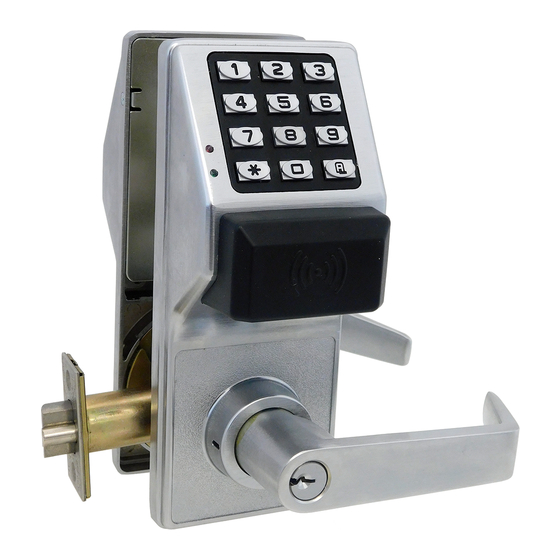
PDL6300 SECONDARY SIDE
PDL6300 PRIMARY SIDE
(CONTAINS BATTERIES AND MOUNTING SCREWS)
(CONTAINS ANTENNA AND METAL KEY CYLINDER)
AL-IM2 SERIES
"VERSION 2"
GATEWAY MODULES
AL-IM2-80211
DL-WINDOWS PROGRAMMING
AL-IME2
SOFTWARE
AL-IME2POE
PROXIMITY KEYFOB
PROXIMITY
CREDENTIAL
AL-IM2-PIE PLUG-IN
AL-IME-USB
EXPANDER MODULE
GATEWAY MODULE
Double-Sided PDL Trilogy Series Stand-Alone Access
Control Systems with Proximity Credential Access
1
Advertisement
Table of Contents

Related Manuals for Alarm Lock Wireless Trilogy PDL6300


Summary of Contents for Alarm Lock Wireless Trilogy PDL6300
- Page 1 (Note: Technical Service is for security professionals only) Publicly traded on NASDAQ Symbol: NSSC © ALARM LOCK 2018 WI2265LF 1/18 PDL6300 SECONDARY SIDE PDL6300 PRIMARY SIDE (CONTAINS BATTERIES AND MOUNTING SCREWS) (CONTAINS ANTENNA AND METAL KEY CYLINDER) AL-IM2 SERIES "VERSION 2"...
-
Page 2: Table Of Contents
Remote Input momentary contact, a Wireless Remote Release, or any future device or design that allows the lock to ® ® ® © unlock, allowing passage through the door. Trilogy is a registered trademark of Alarm Lock. ProxCard and ProxKey are trademarks of the HID ® ® Corporation. Microsoft and Windows are trademarks of the Microsoft Corporation. -
Page 3: Lock Features
500 Scheduled Events (see pages 29-31) Keypad and Computer Programming Automated Unlock/Lock Full Administrative programming from a PC using Alarm Lock's Enable/Disable Users (see page 20, Function 3) DL-Windows Software. See the DL-Windows User's Guide Enable/Disable Groups (see page 21) (OI382) and the DL-Windows for Networx User's Guide (OI383) ... -
Page 4: Supported Products And Applications
Locks, connects directly to a network using a standard RJ-45 Ethernet cable. This model has one antenna used to transmit to the Networx series door lock via an Alarm Lock proprietary radio connection. Ceiling- or wall-mountable. Powered with Class 2, 6VAC transformer (supplied). - Page 5 LEDs are different, and the location of the hidden Ethernet socket is through the rear mounting plate. Note: The AL-IME2-POE Gateway is compatible with Alarm Lock and Continental Access products. Refer to the documentation supplied with your software for integration details.
-
Page 6: Lock Design Overview
Software is "soft" -- flexible and changeable to your needs. Software exists inside your Alarm Lock™ series lock, and can be programmed (and re-programmed again and again) to suit your changing requirements. No more metal keys to distribute...instead, distribute User Codes -- and delete them from the lock software when needed. -
Page 7: Terminology Used In This Manual
Can only program functions relating to day to day operation. (Abbreviated as Programming Level = 2). What are Features? Print Only Users: In previous versions of the ALARM LOCK Your lock is designed to support several options and functions. Trilogy series locks, Print Only Users were always associated Using the keypad or DL-Windows software (the Programmable with User Numbers 10 &... - Page 8 DL-Windows is a computer program that allows you to program DL-Windows does not need to be running to allow these your ALARM LOCK T3 Security Lock. DL-Windows is not re- "Emergency" commands to be initiated; any 6300 series lock quired to program your lock, but it makes programming much keypad can be used to disseminate these commands through- faster and easier.
-
Page 9: Programming Levels
Programming Levels The Programming Level defines the range of programming operation. (Abbreviated as Programming Level = 2). tasks a User is allowed to perform. The higher the Level, the Print Only Users: In previous versions of the ALARM more programming tasks the User is allowed (with Master LOCK Trilogy series locks, Print Only Users were always allowing ALL tasks). -
Page 10: Conventions Used In This Manual
Conventions Used in this Manual Enabling/Disabling Users (By User Number) Minimum Required Program Level User Number must be between 2 and 5000. Program Levels are abbreviated as follows: NOTE: Will Enable/Disable users even if the user is associated with an enabled Group. Function M = Master Description... -
Page 11: Emergency Commands
Emergency Commands Emergency Commands The PDL6300 series locks can be programmed to send and/or respond to Emergency Commands ("Emergency Lock Down", "Emergency Passage" and " Return to Normal" ). Emergency Commands can be initiated directly from the lock's keypad, initiated from an RR-4BKEYFOB Wireless Remote Release or initiated from the Networx server running DL- Windows. - Page 12 Emergency Commands (cont'd) tures to customize your system. Example #1: DL-Windows by default enables (checks) all of the features, as shown above in the Features dialog. What will happen when all features are enabled and an "Emergency Lock Down" command is initiated at the keypad? Because the Activate Local Emergency commands are enabled, the lock that initiates the Emergency Command will lock down, then the lock will inform the Gateway to broadcast the Emergency Command to all locks assigned to the same "Gateway Group".
-
Page 13: Wireless Remote Releases
Wireless Remote Releases Overview Two types of "Wireless Remote Release" devices are compatible with the PDL6300 series door lock: The RR-1BUTTON Wireless Remote Release Button (see WI1999) and RR-4BKEYFOB Wireless Re- mote Release Keyfob (see WI2004). Whether the Wireless Remote Release contains a single button (RR-1BUTTON) or four buttons (RR-4BKEYFOB), each button can be "paired"... -
Page 14: Wiring And Power Up
Wiring and Power Up 6. Press and hold down ; for 10 seconds (to ensure all WIRING power is drained from the lock) and release. See the Installation Manual for more information. 7. Connect the batteries and listen for 3 beeps. After Batteries: hearing the 3 beeps, you have 3 seconds to press and hold ;. -
Page 15: Quick Start
Quick Start First Time Start Up 1. Unpack the lock. 2. With the batteries disconnected, hold down the ; key for 10 seconds and release. 3. Connect the batteries and listen for 3 beeps. Within 5 seconds of hearing the 3 beeps, press and hold ; until beeping starts. - Page 16 Quick Start (cont'd) 2. Press ; 2 ; User Number The lock will flash a green LED and beep continuously for 6 seconds. When the red LED flashes, the User Code is deleted. 3. Repeat step 2 for each new User. User Code Conflicts Care should be taken not to program a new User Code which matches the first digits of any other User Code (only the User Code with the least number of digits will be recognized).
-
Page 17: Testing The Codes Entered
Exit Program Mode Hold Down any key for 3 seconds. Program Mode exit is confirmed by several beeps. You are now in normal operation. Re-enter Program Mode If you wish to re-enter Program Mode, key-in your new 6-digit Master Code, and press ;. You are now ready to mount and install your PDL series lock and give out your User Codes. -
Page 18: Programming Functions Overview
Programming Functions--Overview Function 48 Enable Passage Mode See page 25 Function 1 Change Master Code See page 19 Function 49 Disable Passage Mode See page 25 Function 2 Add/Delete/Change User Codes See page 19 Return Lock to Normal Passage Function 50 See page 25 Function 3 User Disable (By User Number) -
Page 19: Programming Functions
Programming Functions [ _ _ _ _ _ _ ] [ _ _ _ _ _ _ ] 1. New Master Code (User Number 1) (New Master Code) (Confirm New Master Code) Master Code must be 6 digits only (cannot be a proximity credential). ... - Page 20 Programming Functions (cont'd) USERS (Continued) User Enable/Disable (By User Number) User Number must be between 2 and 5000. NOTE: Will Enable/Disable Users even if the User is associated with an enabled Group. Use Feature 3 to disable a specific User Number and their associated User Code.
- Page 21 Programming Functions (cont'd) CLEAR FUNCTIONS 12. Clear All Schedules and Timeout Functions ; 1 2 ; 0 0 0 : Function 12 clears all programmed Schedules and all Timeout Functions. (To clear All Timeout Functions only, see Function 13 below). Function 12 will clear all of the following: All Schedule Functions 72 through 93, Timeout Functions 5, 25 through 34 and Function 47.
- Page 22 Programming Functions (cont'd) NOTE: Clear All Timeout Functions by entering Function 13. GROUPS Group Enable/Disable with Timeout (Enter Timeout, XXX Hours) (Functions 25-34 are enabled through the keypad only) Hours must be between 1-999. Enter the functions below to Enable/Disable Groups for the amount of time entered in hours. NOTE: Only 4 Timeout Functions are allowed at any one time.
- Page 23 Programming Functions (cont'd) CLOCK SETTINGS ; 3 8 38. Set Date [ _ _ _ _ _ _ ] (Date) Use Month Day Year format - MMDDYY - Single digit months and days are entered with a preceding zero. ...
- Page 24 Programming Functions (cont'd) CLOCK ADJUST Clock Adjust Number of seconds to adjust (speed up/slow down) the clock each day must be be- tween 0-55 seconds. Note: Repeated use of these Functions are not "cumulative" (this means, for example, if the clock has already been set to speed up 10 seconds per day, and then is found to Clock Accuracy need an additional 10 seconds, then program 20 seconds using Function 43).
- Page 25 Programming Functions (cont'd) PERMANENT PASSAGE MODE Passage Mode Enable/Disable - Schedule will not Override Function 48 allows passage through the door without the need for a User Code. Re-Lock using Function 49. Programmed Schedules will not override the state of the lock using functions 48 and 49. If it is required that programmed schedules override Passage Mode, Enable/Disable Passage Mode using Functions 45/46.
- Page 26 Programming Functions (cont'd) 55 - 59 Reserved LOCKOUT ; 6 0 60. Number of Attempts Before Lockout [ _ ] (Number of Attempts) Number of attempts before lockout must be 1-9 attempts. The number of attempts is reduced by half every time the keypad is locked out without a successful code entry (default is 6 attempts).
- Page 27 Programming Functions (cont'd) ; 6 7 [ _ _ ] 67. Program System Features (Feature Number) Use Function 67 to program one or more system features. Before you implement any of the Function 67 system features described below and on the next page, take note that some features are enabled ("ON") by default (for example, see #39, page 28).
- Page 28 Programming Functions (cont'd) ; 6 7 [ _ _ ] 67. Program System Features (cont'd) (Feature Number) (passage through the door) during an Emergency. 43 Enable Sounder on Emergency. (Default = OFF) Integral sounder beeps for 30 seconds while in Emergency. 45 Activate Local Emergency: Keypad initiates Local Emergency Commands.
- Page 29 Programming Functions (cont'd) ENTER KEY Enter Key When this function is enabled, the User must press after any valid User Code entry. Therefore, this Function allows User Codes to be subsets of other User Codes. For example: 1 2 3 : can be a valid user code; 1 2 3 4 : a valid user code within the same lock.
- Page 30 Programming Functions (cont'd) QUICK SCHEDULES Quick Schedules - Enable Group For your convenience, your lock comes pre-programmed with Quick Schedules, which, when programmed, enable Groups for popular blocks of time. Group members will be enabled during the blocks of time defined below, but will still need to enter their User Codes into the keypad to unlock the lock.
- Page 31 Programming Functions (cont'd) Scheduled Group 4 Enable (Group 1 Activated) Functions 92 and 93 allow you to set up a window of time where if any Group 1 User Code is entered within this window, Group 4 members will be enabled. (Group 4 members will still need to enter their User Codes to enter). For addi- tional information, see Group 1 Activated Features on page 32.
-
Page 32: Groups And Scheduled Group 1 Examples
The following examples detail the more advanced features of the PDL series locks. Although all features and device functions can be programmed using the lock keypad, when programming becomes more complex you may find it easier to use DL-Windows software to program your Alarm Lock security lock. - Page 33 Groups and Scheduled Group 1 Examples (cont'd.) Press ; 2 ; 4 ; 4 5 6 7 8 9 :. 3. Because User 4 does not have a default Group association, make User 4 a member of Group 1 using Function 35: Press ;...
-
Page 34: Programming Record Sheet
Default Values are shown in parentheses. Note: Some of the features listed require a supporting lock model and firmware. Function Function Name Programming Number(s) 43/44 Clock Adjust 0-55 Seconds 52/53/54 Pass Time (3 sec) 10 sec 15 sec Set Lockout Attempts 1-9 Attempts Set Lockout Time... -
Page 35: User Code Record Sheet
User Number User Code Group User Name (1-5000) (3-6 digits) Association Note: For a complete list of User Codes, obtain a printout from either the remote printer (Program Function 56) or by using the DL-WINDOWS software. - Page 36 User Number User Code Group User Name (1-5000) (3-6 digits) Association Note: For a complete list of User Codes, obtain a printout from either the remote printer (Program Function 56) or by using the DL-WINDOWS software.
-
Page 37: Schedule Record Sheet
Day(s) Up to 500 scheduled functions can be programmed (Up to only 150 using AL-DTM). For Day Enter : 1 = Sunday, 2 = Monday, 3 = Tuesday, 4 = Wednesday Function Number Time Function Name 5 = Thursday, 6 = Friday, 7 = Saturday, 8 = Monday through Friday, 9 = Saturday and Sunday, 0 = All days of the week Enter time of day in 24-hour format (00:00- 23:59) -
Page 38: Glossary
Power-Up, page 14), the original factory default PRINT ONLY USER CODE = In previous settings are re-loaded and take effect. versions of the ALARM LOCK Trilogy series DISABLE = Turn off. locks, Print Only Users were always associated with User Numbers 10 & 11 and were restricted... - Page 39 Glossary (cont'd) FUNCTION (also called Programming Functions) = MANAGER = See... CODE, MANAGER CODE. are the numbers used to program lock features MASTER = See... CODE, MASTER CODE. (enabling/disabling Users, User Groups, Passage Mode, Schedules, etc.). PASSAGE = Allow anyone to pass through the door without USER CODES (door is unlocked).
-
Page 40: Warranty
This warranty shall not apply to any equipment, or any part In no event shall ALARM LOCK be liable for an amount in thereof, which has been repaired by others, improperly excess of ALARM LOCK's original selling price of the...
Need help?
Do you have a question about the Wireless Trilogy PDL6300 and is the answer not in the manual?
Questions and answers