Table of Contents
Advertisement
12/14 Rev. 03
Commissioning & Operation
Mounting the Printer ...................................... 2
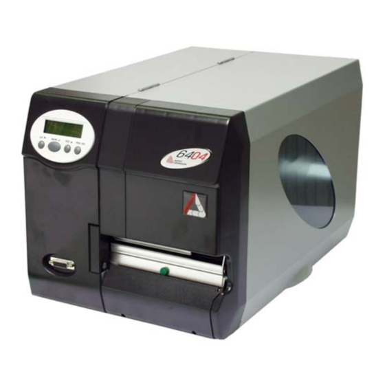
Unpacking the 64-xx ................................. 2
Carrying the 64-xx ..................................... 3
Mounting the 64-xx .................................... 4
Printer connections ................................... 5
Operator panel .......................................... 7
Operating modes ....................................... 9
Basic Operating Procedures ....................... 11
Connecting the printer ............................. 11
Switching on the printer ........................... 12
Configuring the data interface ................. 12
USER MANUAL
64-xx
Offline operation ......................................13
Online operation ......................................14
Creating a print job ..................................15
Transferring a print job .............................15
Applying memory cards ...........................17
Setting the realtime clock .........................18
Easy Plug .................................................18
Starting to print ............................................19
Settings for the material type ...................19
Printing the status report ..........................19
Advertisement
Chapters
Table of Contents

Related Manuals for Avery Dennison 64-Series


Summary of Contents for Avery Dennison 64-Series
-
Page 1: Table Of Contents
12/14 Rev. 03 USER MANUAL 64-xx Commissioning & Operation Mounting the Printer ........2 Offline operation ........13 Unpacking the 64-xx ......... 2 Online operation ........14 Carrying the 64-xx ........3 Creating a print job ........15 Mounting the 64-xx ........4 Transferring a print job ......15 Printer connections ........ -
Page 2: Mounting The Printer
12/14 Rev. 03 USER MANUAL Commissioning & Operation 64-xx Mounting the Printer Unpacking the 64-xx 1. Lift off the lid of the shipping box [1]. 2. Take out the plastic bag containing the accessories [1B]. 3. Lift off the styrofoam support [1A]. 4. -
Page 3: Carrying The 64-Xx
12/14 Rev. 03 USER MANUAL Commissioning & Operation 64-xx Carrying the 64-xx WARNING! The 64-xx is a heavy printer. The weight depends on the printer type and equipement and can vary from 20 kg (64-04/05) up to 29.5 kg (64-08 Dis- penser). -
Page 4: Mounting The 64-Xx
12/14 Rev. 03 USER MANUAL Commissioning & Operation 64-xx Mounting the 64-xx The 64-xx has been designed as a desktop printer, which means that it is normally mounted in an upright position on a table [2]. Other sufficiently large, level and sturdy surfaces can also be used as a base. WARNING! When choosing a base for the printer, observe the following guidelines to avoid dangerous operating conditions:... -
Page 5: Printer Connections
12/14 Rev. 03 USER MANUAL Commissioning & Operation 64-xx Printer connections CAUTION! Add-on devices of an inferior quality may damage the printer! Connect the printer only to devices that fulfil SELV (safety extra-low volta- ge) circuit requirements acc. to EN 60950! ... - Page 6 12/14 Rev. 03 USER MANUAL Commissioning & Operation 64-xx H Optional: Signal interface USI • 4 inputs / 8 outputs • Standard at „64-xx Dispenser A“ I Optional: Mini-DIN connector To connect a remote operator panel J Optional: start/stop signal input •...
-
Page 7: Operator Panel
12/14 Rev. 03 USER MANUAL Commissioning & Operation 64-xx Operator panel Display Prog button Feed button Online button Cut button Operator panel of the 64-xx. Display With 32 digits and two lines, the display shows the operating conditions (mo- des) for parameters, values, status and errors. You can select the language you want to use for the display. - Page 8 12/14 Rev. 03 USER MANUAL Commissioning & Operation 64-xx – Chapter Offline operation on page 13 and Chapter Online operation on page 14 – In topic section Info-Printouts and Parameter Remote operator 64-0x Gen. 3 (or higher) machines can be equipped with a remote operator panel panel.
-
Page 9: Operating Modes
12/14 Rev. 03 USER MANUAL Commissioning & Operation 64-xx Operating modes Offline mode Printer settings can be made when the device is offline. The offline mode is normally active when the printer is switched on. Print jobs are received via the selected interface but not processed. - Page 10 12/14 Rev. 03 USER MANUAL Commissioning & Operation 64-xx Standalone mode In standalone mode, print jobs are not transferred but saved on a plugin card. They are started directly from the printer’s operator panel or via a connected keyboard. Standalone mode: see topic section „Advanced Applications“.
-
Page 11: Basic Operating Procedures
12/14 Rev. 03 USER MANUAL Commissioning & Operation 64-xx Basic Operating Procedures Connecting the printer WARNING! The printer operates using mains voltage! Touching electrically live parts can cause exposure to hazardous electrical currents and may lead to burns. Make sure that the printer is switched off before connecting the power ca- ble. -
Page 12: Switching On The Printer
12/14 Rev. 03 USER MANUAL Commissioning & Operation 64-xx Switching on the printer Turn on the printer using the power switch (set to position “1”). The following sequence of messages is displayed: System start... The boot loader is starting. System start... -
Page 13: Offline Operation
12/14 Rev. 03 USER MANUAL Commissioning & Operation 64-xx Offline operation • Switching from offline mode to online mode: OFFLINE x JOBS ONLINE x JOBS Online • Switch to online mode when the print job is stopped: OFFLINE x JOBS ONLINE x JOBS Online... -
Page 14: Online Operation
12/14 Rev. 03 USER MANUAL Commissioning & Operation 64-xx Online operation • Switching to offline mode: ONLINE x JOBS OFFLINE x JOBS Online • Setting the print contrast: Press the Feed button to increase and the Cut button to decrease the print contrast. ONLINE x JOBS Print contrast... -
Page 15: Creating A Print Job
12/14 Rev. 03 USER MANUAL Commissioning & Operation 64-xx Creating a print job Essentially, there are two ways of creating a print job: Either by using the 64-xx Windows printer driver, or by creating a text file using print commands. Windows printer 64-xx printer drivers are available for different versions of Windows. - Page 16 12/14 Rev. 03 USER MANUAL Commissioning & Operation 64-xx clicking PROPERTIES > SHARE (in Windows XP). The sharename stands for a printer, which is connected to a certain port. This is the USB port for tranferring via USB and the TCP/IP port for transferring by Ethernet. A few hints on using the USB interface: ...
-
Page 17: Applying Memory Cards
CF card. When inserting or removing the CF card, never use force. Flawless functioning of the memory cards is only guaranteed for the types distributed by Avery Dennison: Wide guide notch Slim guide notch Contacts [12] CF card (article no. -
Page 18: Setting The Realtime Clock
12/14 Rev. 03 USER MANUAL Commissioning & Operation 64-xx SD card: 1. Switch off the printer. Wait for 5 seconds. 2. Press onto the memory card, until it unlocks. Remove the memory card from the card slot. [14] Inserting a memory card (A: CF, B: SD). If the memory card has been inserted correctly, it will sit flush with the printer’s back wall (right). -
Page 19: Starting To Print
12/14 Rev. 03 USER MANUAL Commissioning & Operation 64-xx Starting to print Settings for the material type The parameter settings described below provide the printer with the neces- sary information about the label material used. When printing from a layout program, these settings are usually provided automatically by the printer driver. - Page 20 12/14 Rev. 03 USER MANUAL Commissioning & Operation 64-xx The heat energy should be kept as low as possible while retaining an accep- table printing result. A high level of heat energy reduces the lifespan of the printhead.
-
Page 21: Setting Up
03/13 Rev. 5.08-01 USER MANUAL 64-xx – 64-xx dispenser Setting up Winding diagrams ......... 2 Material / Ribbon end ........11 64-xx ............2 Material end ..........11 Designation of parts ........2 Ribbon end ..........11 64-xx dispenser ......... 3 Rewinder full ..........11 Designation of parts ........ -
Page 22: Winding Diagrams
03/13 Rev. 5.08-01 USER MANUAL Einrichten 64-xx – 64-xx dispenser Winding diagrams The winding diagrams show the winding direction of material and ribbon through the 64-xx or through the 64-xx dispenser printer. You must follow this basic schema when inserting/changing material and ribbon. ... -
Page 23: 64-Xx Dispenser
03/13 Rev. 5.08-01 USER MANUAL Einrichten 64-xx – 64-xx dispenser 64-xx dispenser [15] This is how to insert material and ribbon correctly in the 64-xx dispenser (each of type M). Designation of parts No. Designation No. Designation Ribbon unwind mandrel Dispensing edge Ribbon deflector Feed roller... -
Page 24: Selecting Ribbon/Material
03/13 Rev. 5.08-01 USER MANUAL Einrichten 64-xx – 64-xx dispenser Selecting ribbon/material Label material When selecting the material, you must take 3 factors into account: – the abrasive behavior of the surface structure of the material; – the properties with regard to the chemical reaction when printing ink is transferred;... -
Page 25: Inserting Material
03/13 Rev. 5.08-01 USER MANUAL Einrichten 64-xx – 64-xx dispenser Inserting material CAUTION! Rotating axles! These can pull in and tear off hair, clothing and jewelry. – Do not operate the machine with the hood open! – Keep long hair, loose clothing, jewelry etc. - Page 26 03/13 Rev. 5.08-01 USER MANUAL Einrichten 64-xx – 64-xx dispenser Only 64-xx dispenser: 9. Guide material through under the dis- penser roller (1). 10. Pull labels off the backing paper over a length of about 50 cm (Fig. 1). 11.
- Page 27 03/13 Rev. 5.08-01 USER MANUAL Einrichten 64-xx – 64-xx dispenser Continued on next page. 14. Guide the backing paper around the feed roller (1) and guide pins (2) of the drawing module to form an S shape (Fig. 1). 15.
-
Page 28: Inserting Fan-Folded Material
03/13 Rev. 5.08-01 USER MANUAL Einrichten 64-xx – 64-xx dispenser Inserting fan-folded material 1. Set the outer disc of the material unwinder to the width of the material. 2. Pull the material through the inlet opening (1) to the material guide with the side to be printed showing upwards. -
Page 29: Changing Material
03/13 Rev. 5.08-01 USER MANUAL Einrichten 64-xx – 64-xx dispenser Changing material Proceed as described in the following to replace an inserted material roll befor it comes to an end. The printer must be switched on; otherwise, the printhead presses on the material. -
Page 30: Inserting Ribbon
03/13 Rev. 5.08-01 USER MANUAL Einrichten 64-xx – 64-xx dispenser Inserting ribbon 1. Switch the printer on. 2. Open the hood of the printer. 3. Place the roll of ribbon on the right ribbon mandrel (1) so that it can unwind anti- clockwise. -
Page 31: Material / Ribbon End
03/13 Rev. 5.08-01 USER MANUAL Einrichten 64-xx – 64-xx dispenser Material / Ribbon end Material end If the material end has passed the material guiding, the following status message appears: Status 5002 Material end 1. Press the opener and pull the remaining material from the front side (display side) out of the print unit. -
Page 32: Settings For All Printers
03/13 Rev. 5.08-01 USER MANUAL Einrichten 64-xx – 64-xx dispenser Settings for all printers Ribbon tension The torques of the ribbon unwind mandrel (1) and ribbon rewind mandrel (2) can be set using the red plastic hexagons on the ribbon mandrels. -
Page 33: Material Light Barrier
03/13 Rev. 5.08-01 USER MANUAL Einrichten 64-xx – 64-xx dispenser Material light barrier The series 64-xx printers are fitted with transmitted-light light barriers. Reflector light barriers are also available as an option. To set Setting is performed by means of the red rotary knob (1) on the outside of the print module. -
Page 34: Print Head Contact Pressure
03/13 Rev. 5.08-01 USER MANUAL Einrichten 64-xx – 64-xx dispenser Print head contact pressure Different material widths and/or material thicknesses have an effect on the contact pressure of the thermal strip on the feed roller. The contact pressure can be set in 3 steps: Position for 64-04/05 or for thin/narrow material up to the maximum print width of the 64-05 (1) -
Page 35: Adjusting The Position Of The Print Head
03/13 Rev. 5.08-01 USER MANUAL Einrichten 64-xx – 64-xx dispenser Adjusting the position of the print head Only for the standard version of 64-05/ 06/08! The print head 0 line can be adjusted va- riably from 2 mm (from the left edge of the label) to 13 mm: 1. -
Page 36: Material Parameters
03/13 Rev. 5.08-01 USER MANUAL Einrichten 64-xx – 64-xx dispenser Material parameters The following three parameters are used to tell the printer the properties of the label material with which you would like to work: Parameter Function PRINT PARAMETER > material type Sets the type of material (punched or continuous) PRINT PARAMETER >... -
Page 37: Settings At 64-Xx Dispensers
03/13 Rev. 5.08-01 USER MANUAL Einrichten 64-xx – 64-xx dispenser Settings at 64-xx dispensers Dispenser types The 64-xx is available as „Dispenser M“ or „Dispenser A“ (see tab. 2). Type Property Operating mode • Short dispensing edge with Printing/dispensing is triggered manually label sensor (single start), e. -
Page 38: Parameter Settings For „64-Xx Dispenser M
03/13 Rev. 5.08-01 USER MANUAL Einrichten 64-xx – 64-xx dispenser Information about operation with start signal can be found in topic section Advanced Applications, chapter „Printing with start signal“. Parameter settings for „64-xx dispenser M“ The printing/dispensing process can be triggered by foot switch or by light barrier: Foot switch The values preset by the manufacturer (see tab. -
Page 39: Index
03/13 Rev. 5.08-01 USER MANUAL Setting up 64-xx – 64-xx dispenser Index Changing material Material end Designation of parts Rewinder full - 64-xx Ribbon end - 64-xx dispenser Dispenser Setting label material parameters - parameters for version A Setting the material light barrier - parameters for version M Setting the position of the print head Drawing module... - Page 40 11/14 Rev. 03 USER MANUAL AP 4.4 – AP 5.4 – AP 5.6 – AP 7.t – 64-xx – DPM – PEM – ALX 92x Advanced Applications Printing with temperature compensation ..2 Access via Web/FTP server .......21 Requirements ..........2 Web server ..........21 Function description ........
-
Page 41: Advanced Applications
11/14 Rev. 03 USER MANUAL Advanced Applications AP 4.4 – AP 5.4 – AP 5.6 – AP 7.t – 64-xx – DPM – PEM – ALX 92x Printing with temperature compensation Requirements • Suitable printers: All devices listed in the headline of this document •... - Page 42 11/14 Rev. 03 USER MANUAL Advanced Applications AP 4.4 – AP 5.4 – AP 5.6 – AP 7.t – 64-xx – DPM – PEM – ALX 92x Drive performance print head TR=0 TR=20% TR=40% TR = “SYSTEM PARAMETERS / Temp. reduction” °C Print head temperature...
-
Page 43: Printing With Start Signal
11/14 Rev. 03 USER MANUAL Advanced Applications AP 4.4 – AP 5.4 – AP 5.6 – AP 7.t – 64-xx – DPM – PEM – ALX 92x Printing with start signal Application notes Print-and-Apply systems are normally triggered by an external start signal, which typ- ically comes from a product sensor placed at the conveyor. -
Page 44: Connecting The Signal Source
11/14 Rev. 03 USER MANUAL Advanced Applications AP 4.4 – AP 5.4 – AP 5.6 – AP 7.t – 64-xx – DPM – PEM – ALX 92x Connecting the signal source Footswitch Footswitches are available as accessory for both, 64-xx and AP 5.4/5.6 printers and are shipped ready configured (see topic section Accessories ). - Page 45 11/14 Rev. 03 USER MANUAL Advanced Applications AP 4.4 – AP 5.4 – AP 5.6 – AP 7.t – 64-xx – DPM – PEM – ALX 92x USI, AI, E/A The 3 accessory boards USI, AI and I/O provide each a signal interface shaped as a D-Sub connector [2B] [3A].
-
Page 46: Settings In The Parameter Menu
11/14 Rev. 03 USER MANUAL Advanced Applications AP 4.4 – AP 5.4 – AP 5.6 – AP 7.t – 64-xx – DPM – PEM – ALX 92x Settings in the parameter menu Setting Interface Printer Parameter Value Accept start si- SYSTEM PARAMETER >... -
Page 47: Standalone Operation
11/14 Rev. 03 USER MANUAL Advanced Applications AP 4.4 – AP 5.4 – AP 5.6 – AP 7.t – 64-xx – DPM – PEM – ALX 92x Standalone Operation Requirements Printer Suitable printers: all devices listed in the headline of this document, except for AP 4.4 (which has no card slot) Firmware Printer... -
Page 48: Functional Description
11/14 Rev. 03 USER MANUAL Advanced Applications AP 4.4 – AP 5.4 – AP 5.6 – AP 7.t – 64-xx – DPM – PEM – ALX 92x Keyboard On request, a keyboard can be connected to the printer. This considerably simplifies entry of variable data, especially when dealing with text. -
Page 49: Selecting Files From Memory Card
11/14 Rev. 03 USER MANUAL Advanced Applications AP 4.4 – AP 5.4 – AP 5.6 – AP 7.t – 64-xx – DPM – PEM – ALX 92x Features Standalone operation in brief: • Printing without computer connection • Data entry via control panel or keyboard •... -
Page 50: Executing Printjobs
11/14 Rev. 03 USER MANUAL Advanced Applications AP 4.4 – AP 5.4 – AP 5.6 – AP 7.t – 64-xx – DPM – PEM – ALX 92x 3. Press the Online button to start proceeding the file In case of a printjob file, the printjob is started, in case of a firmware file, the firm- ware upload starts. - Page 51 11/14 Rev. 03 USER MANUAL Advanced Applications AP 4.4 – AP 5.4 – AP 5.6 – AP 7.t – 64-xx – DPM – PEM – ALX 92x mation about the job is displayed in the "Print control" console. While the print job is processed, it is started newly in the „Standalone“...
-
Page 52: Executing Firmware Files
11/14 Rev. 03 USER MANUAL Advanced Applications AP 4.4 – AP 5.4 – AP 5.6 – AP 7.t – 64-xx – DPM – PEM – ALX 92x Executing firmware files Files with the extension .S3B are firmware files. Selecting a firmware file means start- ing a firmware download. -
Page 53: Insert Input Field In Printjob
11/14 Rev. 03 USER MANUAL Advanced Applications AP 4.4 – AP 5.4 – AP 5.6 – AP 7.t – 64-xx – DPM – PEM – ALX 92x Insert Input Field in Printjob Input fields can be defined in the following Easy Plug field types: •... - Page 54 11/14 Rev. 03 USER MANUAL Advanced Applications AP 4.4 – AP 5.4 – AP 5.6 – AP 7.t – 64-xx – DPM – PEM – ALX 92x 7. Simultaneously press the Online and ESC keys. The first file on the memory card is displayed: Choose a file AVERY .FOR...
-
Page 55: Data Input By Interface
11/14 Rev. 03 USER MANUAL Advanced Applications AP 4.4 – AP 5.4 – AP 5.6 – AP 7.t – 64-xx – DPM – PEM – ALX 92x Data input by interface Available with firmware x.33 or a later version. Apart from putting in data by operation panel or by external keyboard, the data can be sent via interface. -
Page 56: Data Transmission With Ethernet
11/14 Rev. 03 USER MANUAL Advanced Applications AP 4.4 – AP 5.4 – AP 5.6 – AP 7.t – 64-xx – DPM – PEM – ALX 92x Data Transmission with Ethernet System Requirements CAUTION! - Unqualified manipulations of a data network can disturb or stop its pro- per functioning. -
Page 57: Integration Of Ethernet Interface
11/14 Rev. 03 USER MANUAL Advanced Applications AP 4.4 – AP 5.4 – AP 5.6 – AP 7.t – 64-xx – DPM – PEM – ALX 92x Integration of Ethernet Interface The Ethernet interface of the printers is layed out as 10/100 Base T. The transmission speed is set by autonegotiation. -
Page 58: Setting The Ip Parameters
11/14 Rev. 03 USER MANUAL Advanced Applications AP 4.4 – AP 5.4 – AP 5.6 – AP 7.t – 64-xx – DPM – PEM – ALX 92x Setting the IP Parameters The IP-parameter settings can either be set fix, or they can be requested from a DHCP server with every start of the printer. -
Page 59: Transmission With Lpd Server
11/14 Rev. 03 USER MANUAL Advanced Applications AP 4.4 – AP 5.4 – AP 5.6 – AP 7.t – 64-xx – DPM – PEM – ALX 92x Transmission with LPD Server Printing data can be transmitted to the printer using the LPR/LPD (Line Printer Dae- mon) protocol (“BSD Spooler”). -
Page 60: Access Via Web/Ftp Server
11/14 Rev. 03 USER MANUAL Advanced Applications AP 4.4 – AP 5.4 – AP 5.6 – AP 7.t – 64-xx – DPM – PEM – ALX 92x Access via Web/FTP server Web server Applications The web server makes it possible •... - Page 61 H Click on this button after entering user name and password Displays the machine model Displays the firmware version K Links to the Avery Dennison Machinery website Logging in to the web 1. Click on the “Login” link [9B] server 2.
- Page 62 11/14 Rev. 03 USER MANUAL Advanced Applications AP 4.4 – AP 5.4 – AP 5.6 – AP 7.t – 64-xx – DPM – PEM – ALX 92x Changing a setting in Click on the names of submenus and parameters to open them so that you can the labeller menu change the settings they contain.
- Page 63 11/14 Rev. 03 USER MANUAL Advanced Applications AP 4.4 – AP 5.4 – AP 5.6 – AP 7.t – 64-xx – DPM – PEM – ALX 92x The virtual operator panel [12] The virtual operator panel After the “Display view” link is clicked, an image of the operator panel (= virtual oper- ator panel) appears on the screen [12].
-
Page 64: Ftp Server
11/14 Rev. 03 USER MANUAL Advanced Applications AP 4.4 – AP 5.4 – AP 5.6 – AP 7.t – 64-xx – DPM – PEM – ALX 92x D Status line [13E] In order to avoid putting an operating person at the machine at risk by sudden starting up of the machine, the virtual operator panel is locked as soon as a button at the machine operator panel is pressed. - Page 65 11/14 Rev. 03 USER MANUAL Advanced Applications AP 4.4 – AP 5.4 – AP 5.6 – AP 7.t – 64-xx – DPM – PEM – ALX 92x 4. Enter user name and password. A user name can be chosen at will; preset password = “avery” INTERFACE PARA >NETWORK PARAM.
- Page 66 11/14 Rev. 03 USER MANUAL Advanced Applications AP 4.4 – AP 5.4 – AP 5.6 – AP 7.t – 64-xx – DPM – PEM – ALX 92x If the login was successful, separate folders appear in the FTP client, one for the in- ternal RAM disk and one for each connected memory medium [13]: •...
-
Page 67: Data Transmission With Wlan
11/14 Rev. 03 USER MANUAL Advanced Applications AP 4.4 – AP 5.4 – AP 5.6 – AP 7.t – 64-xx – DPM – PEM – ALX 92x Data transmission with WLAN According to standard IEEE 802.11b Requirements Suitable printers Printer Firmware AP 5.4, AP 7.t 3.00... -
Page 68: Printer Setup
11/14 Rev. 03 USER MANUAL Advanced Applications AP 4.4 – AP 5.4 – AP 5.6 – AP 7.t – 64-xx – DPM – PEM – ALX 92x Printer setup CAUTION! - Network manipulations can disturb or avoid proper network operation. ... -
Page 69: Pc Setup
11/14 Rev. 03 USER MANUAL Advanced Applications AP 4.4 – AP 5.4 – AP 5.6 – AP 7.t – 64-xx – DPM – PEM – ALX 92x PC setup 1. In Windows XP call: Start > Settings > System > Network. 2. -
Page 70: Testing The Connection
11/14 Rev. 03 USER MANUAL Advanced Applications AP 4.4 – AP 5.4 – AP 5.6 – AP 7.t – 64-xx – DPM – PEM – ALX 92x Testing the connection 1. Call the input window: Start > Programs > Accessories > Input prompt. 2. -
Page 71: Storing And Transferring Parameter Settings
11/14 Rev. 03 USER MANUAL Advanced Applications AP 4.4 – AP 5.4 – AP 5.6 – AP 7.t – 64-xx – DPM – PEM – ALX 92x Storing and transferring parameter settings Recommendations • Suitable printers: All printers listed in the headline, apart from the AP 4.4 (which has no card slot) •... -
Page 72: Storing Settings On Memory Card
11/14 Rev. 03 USER MANUAL Advanced Applications AP 4.4 – AP 5.4 – AP 5.6 – AP 7.t – 64-xx – DPM – PEM – ALX 92x Storing settings on memory card SPECIAL FUNCTION > Store parameters 1. Call parameter ... -
Page 73: Loading Settings From Memory Card
11/14 Rev. 03 USER MANUAL Advanced Applications AP 4.4 – AP 5.4 – AP 5.6 – AP 7.t – 64-xx – DPM – PEM – ALX 92x Loading settings from memory card All files with parameter settings, which are stored in the \FORMATS directory, can be read out using the standalone mode. -
Page 74: Verifying Bar Codes With Olv
11/14 Rev. 03 USER MANUAL Advanced Applications AP 4.4 – AP 5.4 – AP 5.6 – AP 7.t – 64-xx – DPM – PEM – ALX 92x Verifying Bar Codes with OLV System Requirements Printer • Suitable printers: 64-xx / DPM / PEM / ALX 92x. •... -
Page 75: Setup
11/14 Rev. 03 USER MANUAL Advanced Applications AP 4.4 – AP 5.4 – AP 5.6 – AP 7.t – 64-xx – DPM – PEM – ALX 92x Setup 1. Place the printer on the OLV mounting plate as illustrated. Operating the OLV at a DPM / PEM / ALX 92x requires a support stand match- ing the respective installation situation 2. - Page 76 11/14 Rev. 03 USER MANUAL Advanced Applications AP 4.4 – AP 5.4 – AP 5.6 – AP 7.t – 64-xx – DPM – PEM – ALX 92x [22] 64-05 with OLV mounted (side view).
-
Page 77: Appendix
11/14 Rev. 03 USER MANUAL Advanced Applications AP 4.4 – AP 5.4 – AP 5.6 – AP 7.t – 64-xx – DPM – PEM – ALX 92x Appendix Example: Setup file for AP 5.4 #!A1 #G Machine Setup for AP 5.4 300 Dpi Version: V3.10 #G Serial number... - Page 78 11/14 Rev. 03 USER MANUAL Advanced Applications AP 4.4 – AP 5.4 – AP 5.6 – AP 7.t – 64-xx – DPM – PEM – ALX 92x #G------------------------------------------------------------------- #G COM2 Port Parameter #G------------------------------------------------------------------- #PC1302/5 Baud rate : 9600 Baud #PC1303/8 No.
- Page 79 11/14 Rev. 03 USER MANUAL Advanced Applications AP 4.4 – AP 5.4 – AP 5.6 – AP 7.t – 64-xx – DPM – PEM – ALX 92x #G------------------------------------------------------------------- #G Options Parameter #G------------------------------------------------------------------- #PC5300/0 Remote Display : Disabled #G------------------------------------------------------------------- #G Printer System Menu #G------------------------------------------------------------------- #PC2001/24.5 Head disp dist.
- Page 80 11/14 Rev. 03 USER MANUAL Advanced Applications AP 4.4 – AP 5.4 – AP 5.6 – AP 7.t – 64-xx – DPM – PEM – ALX 92x #G------------------------------------------------------------------- #G Peripheral Parameter Menu #G------------------------------------------------------------------- #PC2512/1 Rewinder Motor : Generation 2 #PC2501/0 Current mode : Table values #PC2502/100...
- Page 81 11/14 Rev. 03 USER MANUAL Advanced Applications AP 4.4 – AP 5.4 – AP 5.6 – AP 7.t – 64-xx – DPM – PEM – ALX 92x #G MLI Parameter Menu #G------------------------------------------------------------------- #PC4002/15 Darkness : 15 #PC4003/126 Control Prefix : 7EH #PC4004/94 Format Prefix : 5EH...
- Page 82 : Multitech Sys #G readonly ID=30045 #G Work place : FCT Test Station #G readonly ID=30046 #G Company name : Avery Dennison #G------------------------------------------------------------------- #G CF card slot status #G------------------------------------------------------------------- #G readonly ID=30047 #G Card in slot : Yes #G readonly...