
Related Manuals for Advantech EKI-136-MB-BE Series


Summary of Contents for Advantech EKI-136-MB-BE Series
- Page 1 User Manual EKI-136x-MB-BE Series 1/2-port RS-232/422/485 to 802.11a/b/g/n WLAN Modbus Gateway...
- Page 2 No part of this manual may be reproduced, copied, translated or transmitted in any form or by any means without the prior written permission of Advantech Co., Ltd. Information provided in this manual is intended to be accurate and reliable.
- Page 3 Declaration of Conformity This product has passed the CE test for environmental specifications. Test conditions for passing included the equipment being operated within an industrial enclosure. In order to protect the product from being damaged by ESD (Electrostatic Discharge) and EMI leakage, we strongly recommend the use of CE-compliant industrial enclosure products.
- Page 4 Technical Support and Assistance Visit the Advantech web site at www.advantech.com/support where you can find the latest information about the product. Contact your distributor, sales representative, or Advantech's customer service center for technical support if you need additional assistance. Please have the following information ready before you call: –...
- Page 5 The sound pressure level at the operator's position according to IEC 704-1:1982 is no more than 70 dB (A). DISCLAIMER: This set of instructions is given according to IEC 704-1. Advantech disclaims all responsibility for the accuracy of any statements contained herein. EKI-136x-MB-BE Series User Manual...
- Page 6 Safety Precaution - Static Electricity Static electricity can cause bodily harm or damage electronic devices. To avoid damage, keep static-sensitive devices in the static-protective packaging until the installation period. The following guidelines are also recommended: Wear a grounded wrist or ankle strap and use gloves to prevent direct contact to the device before servicing the device.
-
Page 7: Table Of Contents
Contents Chapter Introduction ......... 1 Overview ....................2 Features....................2 Specifications.................... 3 Dimensions ....................4 Chapter Getting Started ........6 Hardware ....................7 2.1.1 Front View..................7 2.1.2 Rear View ..................9 2.1.3 Top View..................9 2.1.4 LED Indicators ................10 Connecting Hardware ................ - Page 8 4.5.6 Access Control................44 4.5.7 Log....................45 Port Configuration ................... 46 4.6.1 Basic ................... 46 4.6.2 Operation ..................47 Monitor ....................50 4.7.1 Setting..................50 4.7.2 Statistic ..................51 4.7.3 Connected IP ................52 Alarm....................... 53 4.8.1 Setting..................53 4.8.2 Event...................
- Page 9 List of Figures Figure 1.1 EKI-1361-MB Dimensions ..................... 4 Figure 1.2 EKI-1362-MB Dimensions ..................... 5 Figure 2.1 EKI-1361-MB Front View....................7 Figure 2.2 EKI-1362-MB Front View....................8 Figure 2.3 Rear View ........................9 Figure 2.4 Top View........................9 Figure 2.5 System LED Panel ......................
- Page 10 Figure 4.18 Monitor > Connected IP ....................52 Figure 4.19 Alarm > Setting......................53 Figure 4.20 Alarm > Event......................55 Figure 4.21 Alarm > LogFile ......................56 Figure 4.22 Administration > System....................56 Figure 4.23 Administration > Syslogd..................... 57 Figure 4.24 Administration >...
-
Page 11: Introduction
Chapter Introduction... -
Page 12: Overview
Overview The EKI-136x-MB-BE Series bring RS-232/422/485 to wireless LAN or LAN. They allow nearly any device with serial ports to connect and share an WLAN network. The EKI-136x-MB-BE Series provide a quick, simple and cost-effective way to bring the advantages of remote management and data accessibility to thousands of devices that cannot connect to a network. -
Page 13: Specifications
Specifications Specifications Description Interface I/O Port EKI-1361-MB: 1 x RJ45 + 1 x RS-232/422/485 EKI-1362-MB: 1 x RJ45 + 2 x RS-232/422/485 Power Connector Terminal block Physical Enclosure Metal shell with solid mounting kits Installation DIN-Rail and Wall mount Dimensions 28.5 x 120 x 85.3 mm (1.12"... -
Page 14: Dimensions
Specifications Description Software Driver Support 32-bit/64-bit Windows XP/Vista/7/8/8.1/10, Windows Server 2003/2008/2008 R2/2012/2012 R2 and Linux Utility Advantech EKI Device Configuration Utility Operation Modes Access Point mode/Station mode Modbus RTU Master/Slave Modbus ASCII Master/Slave Configuration Windows utility, Telnet console, Web Browser... -
Page 15: Figure 1.2 Eki-1362-Mb Dimensions
The following view depicts the EKI-1362-MB. 50.70 [2.00] 15 [0.59] 30 [1.18] 104 [4.09] 6.30 [0.25] 15 [0.59] 95 [3.74] 2-MB-BE Reset 104 [4.09] Figure 1.2 EKI-1362-MB Dimensions EKI-136x-MB-BE Series User Manual... -
Page 16: Getting Started
Chapter Getting Started... -
Page 17: Hardware
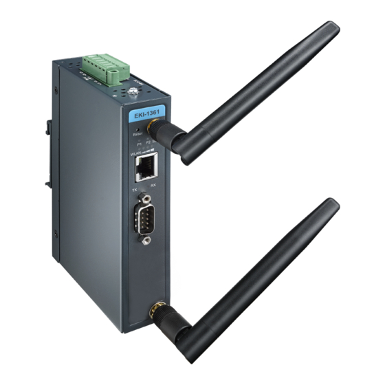
Hardware 2.1.1 Front View The following view shows the EKI-1361-MB. EKI-1361-MB-BE Reset P2 Status Figure 2.1 EKI-1361-MB Front View No. Item Description Antenna connector Connector for antenna. System LED panel See “LED Indicators” on page 10 for further details. ETH port RJ45 ports x 1. -
Page 18: Figure 2.2 Eki-1362-Mb Front View
The following view shows the EKI-1362-MB. EKI-1362-MB-BE Reset P2 Status Figure 2.2 EKI-1362-MB Front View No. Item Description Antenna connector Connector for antenna. System LED panel See “LED Indicators” on page 10 for further details. ETH port RJ45 ports x 1. Serial port DB9 pinout, supports RS-232/422/485. -
Page 19: Rear View
2.1.2 Rear View Figure 2.3 Rear View No. Item Description DIN-Rail mounting Mounting plate used for the installation to a standard DIN rail plate 2.1.3 Top View Figure 2.4 Top View No. Item Description Terminal block Connect cabling for power and alarm wiring Ground terminal Screw terminal used to ground chassis Wall mounting holes Screw holes (x4) used in the installation of a wall mounting plate... -
Page 20: Led Indicators
2.1.4 LED Indicators Reset P2 Status Figure 2.5 System LED Panel Station Mode No. LED Name LED Color Description Green Power 1 is on Power 1 is off or power error condition exists WLAN Status Green WLAN link is ready WLAN is not functioning Green Power 2 is on... -
Page 21: Connecting Hardware
Connecting Hardware 2.2.1 DIN Rail Mounting The DIN rail mount option is the quickest installation option. Additionally, it optimizes the use of rail space. The metal DIN rail kit is secured to the rear of the gateway. The device can be mounted onto a standard 35 mm (1.37”) x 7.5 mm (0.3”) height DIN rail. -
Page 22: Figure 2.7 Correctly Installed Din Rail Kit
See the following figure for an illustration of a completed DIN installation procedure. Figure 2.7 Correctly Installed DIN Rail Kit Grasp the bottom of the gateway and slightly rotate it upwards. If there is resistance, the gateway is correctly installed. Otherwise, re-attempt the installation process from the beginning. -
Page 23: Wall-Mounting
2.2.2 Wall-Mounting The wall mounting option provides better shock and vibration resistance than the DIN rail vertical mount. Note! When installing, make sure to allow for enough space to properly install the cabling. Before the device can be mounted on a wall, you will need to remove the DIN rail plate. -
Page 24: Wireless Connection
Insert the wall sinks into the walls. Align the mounting bracket over the screw holes on the wall. Starting with the upper bracket, insert a screw through the bracket and rotate it to secure. Do not tighten at this point. Repeat for the remaining locations, see the following figure. -
Page 25: Figure 2.12 Positioning The Antenna
Position the antenna for optimal signal strength. Note! The location and position of the antenna is crucial for effective wireless connectivity -B E -M B 1 3 6 2 E K I- s e t Figure 2.12 Positioning the Antenna EKI-136x-MB-BE Series User Manual... -
Page 26: Network Connection
2.2.4 Network Connection For RJ45 connectors, data-quality, twisted pair cabling (rated CAT5 or better) is recommended. The connector bodies on the RJ45 Ethernet ports are metallic and connected to the GND terminal. For best performance, use shielded cabling. Shielded cabling may be used to provide further protection. Straight-thru Cable Wiring Cross-over Cable Wiring Pin 1... -
Page 27: Power Connection
2.2.6 Power Connection 2.2.6.1 Overview Warning! Power down and disconnect the power cord before servicing or wiring the gateway. Caution! Do not disconnect modules or cabling unless the power is first gatewayed off. The device only supports the voltage outlined in the type plate. Do not use any other power components except those specifically designated for the device. - Page 28 2.2.6.2 Considerations Take into consideration the following guidelines before wiring the device: The Terminal Block (CN1) is suitable for 12-24 AWG (3.31 - 0.205 mm ). Torque value 7 lb-in. The cross sectional area of the earthing conductors shall be at least 3.31 mm ...
-
Page 29: Figure 2.16 Grounding Connection
Caution! Do not service any components unless qualified and authorized to do Caution! Do not block air ventilation holes. Electromagnetic Interference (EMI) affects the transmission performance of a device. By properly grounding the device to earth ground through a drain wire, you can setup the best possible noise immunity and emissions. -
Page 30: Figure 2.18 Terminal Receptor: Power Input Contacts
2.2.6.5 Wiring the Power Inputs Caution! Do not disconnect modules or cabling unless the power is first switched off. The device only supports the voltage outlined in the type plate. Do not use any other power components except those specifically designated for the device. -
Page 31: Reset Button
Tighten the wire-clamp screws to secure the DC wires in place. Loosening Securing Wire-clamp Wire-clamp Screws Screws Installing DC Wires Figure 2.20 Installing DC Wires in a Terminal Block Align the terminal block over the terminal block receptor on the gateway. Insert the terminal block and press it in until it is flush with the terminal block receptor. -
Page 32: Utility Configuration
Chapter Utility Configuration... -
Page 33: Installing The Configuration Utility
Microsoft.NET Framework version 2.0 or greater is required for this application. Insert the Advantech EKI Device Configuration Utility CD-ROM into the CD- ROM drive (whereas E:\ is the drive name of your CD-ROM) on the host PC. Use Windows explorer or the Windows Run command to execute the setup program, the path for the setup program on the CD-ROM is as follows: E:\EKI_Device_Configuration_Utility_v2.01.exe... -
Page 34: Figure 3.2 Installshield Wizard 2 Of 4
The Software License Agreement displays, press I Agree to continue or Cancel to stop the installation. Figure 3.2 InstallShield Wizard 2 of 4 The InstallShield continues and a status screen displays. The default installation path is C:\Program Files\EKI Device Configuration Utility. Figure 3.3 InstallShield Wizard 3 of 4 EKI-136x-MB-BE Series User Manual... -
Page 35: Figure 3.4 Installshield Wizard 4 Of 4
Once the installation of the package is finished a Configuration Utility Setup screen displays. Click Finish to conclude the process and exit the InstallShield Wizard. Figure 3.4 InstallShield Wizard 4 of 4 EKI-136x-MB-BE Series User Manual... -
Page 36: Starting The Configuration Utility
Advantech EKI Device Configuration Utility is an excellent device management tool. You can connect and configure the local and remote Advantech devices easily. The utility provides access to the following functions: ... -
Page 37: Discovering Your Device
3.3.1 Auto Searching Advantech EKI Device Configuration Utility will automatically search all the EKI-136x- MB-BE Series devices on the network and show them on the Device List Area of the utility. The utility provides an auto-search function to show your device(s) by simply executing the configuration utility program from the Start Menu. -
Page 38: Figure 3.7 Selecting A Group
Information”, and “Serial Port Information”. The serial port information frame displays the operation mode, status and connected host IP. Figure 3.7 Selecting a Group Click on the “+” before the device name, and the utility will expand the interfaces on this device. -
Page 39: Network Settings
Network Settings Prior to setting up the server’s IP address determine the IP address mode. There are four mode types available: Static IP: mode to assign a specific assigned address DHCP / AutoIP: mode to automatically assign IP addresses through a DHCP server ... -
Page 40: Figure 3.11 Network Settings Overview
You can choose from four possible IP Configuration modes --- Static, DHCP, BOOTP, and DHCP/BOOTP. Figure 3.11 Network Settings Overview Item Description Static IP Static IPUser defined IP address, Subnet Mask, and Default Gateway. DHCP + Auto-IP DHCP Server assigned IP address, Subnet Mask, Default Gateway, and DNS. -
Page 41: Administrator Settings
Administrator Settings 3.5.1 Locate the Device When devices are connected to the network, identification of a specific serial device is possible through the Locate function. To locate the device: From the device list frame, locate the desired device and right-click on it to display the settings menu. -
Page 42: Restore To Factory Default Settings
3.5.2 Restore to Factory Default Settings The configuration utility provides the function to restore the device to factory default settings. Figure 3.13 Restore to Factory Default Settings The confirm message will display after clicking Restore to Factory Default Settings. If you really want to restore the serial device sever to factory default settings, please click Yes button to continue. -
Page 43: Resetting The Device
3.5.3 Resetting the Device The Reset Device is available to allow you to reset the device. The function disconnects both the ethernet and serial connections. The function also allows the device to save new configuration settings to flash memory. Once a new setting is changed, you can use the Save function to accept the changes. -
Page 44: Add To Favorite
3.5.4 Add to Favorite The Add to Favorite function allows to easily map available devices to Favorite’s. By bookmarking specific devices, you can create quickly accessible shortcuts for existing critical devices from the vast pool of locally or remotely networked EKI-136x- MB-BE Series devices. -
Page 45: Update Firmware
3.5.5 Update Firmware Advantech continually upgrades its firmware to keep up with the ever-expanding world of computing. You can use the update firmware function in the utility to carry upgrade procedure. Please access Advantech’s website: http:// www.advantech.com to download the latest version of the firmware. Before updating the firmware, make sure that your host’s Network domain is as same as the device or... -
Page 46: Web Interface
Chapter Web Interface... -
Page 47: Overview
Overview EKI-136x-MB-BE Series device can be configured through a web interface. By using a standard web browser, the same procedure as with the Windows configuration utility can be used. In the browser’s address field, enter the IP Address of your EKI- 136x-MB-BE Series device. -
Page 48: Accessing The Web Page Via Web Browser
4.2.2 Accessing the Web Page via Web Browser Once the device is installed and connected, power on the device. The following information guides you through the logging in process. Launch your web browser on the PC. In the browser’s address bar, type the device’s default IP address (LAN Interface 1: 10.0.0.1). -
Page 49: Network Settings
Item Description Local Network Local IP Address Displays the assigned IP address of the device. Local Netmask Displays the assigned netmask of the device. MAC Address Displays the MAC address of the device. Network Settings 4.4.1 To access this page, click Network Settings > LAN. Figure 4.3 Network Settings >... -
Page 50: Wireless Settings
Note! All new configurations will take effect after rebooting. To reboot the device, click Administration > Tools > Reboot. Wireless Settings 4.5.1 Basic To access this page, click Wireless Settings > Basic. Figure 4.4 Wireless Settings > Basic The following table describes the items in the previous figure. Item Description Wireless Network... -
Page 51: Advanced
Item Description Channel Selection Click the drop-down menu to select Auto (default) or Manual. The Auto selection allows the device to select a band. The Manual selection provides access to a selection of the option band (2.4G / 5G). Band Click the drop-down menu to select the band channel. -
Page 52: Security
Item Description Disassociate Timer The set value in seconds defining the disassociation period. Once the condition is met, the defined watchdog action is triggered. Ping target Enter the IP address to ping when Watchdog Ping is selected. Ping Waittime Enter a value in seconds to designate the interval between pings. Ping Loss Counter Enter a value to activate the Watchdog function when the configuraed number of ping failure time is reached. -
Page 53: Statistics
4.5.4 Statistics To access this page, click Wireless Settings > Statistics. Figure 4.7 Wireless Settings > Statistics The following table describes the items in the previous figure. Item Description Overview Mode Display the current operation mode of the device. SSID Display the SSID. -
Page 54: Site Survey
4.5.5 Site Survey To access this page, click Wireless Settings > Site Survey. Figure 4.8 Wireless Settings > Site Survey The following table describes the items in the previous figure. Item Description Refresh Click Refresh to update the screen. 4.5.6 Access Control The Access Control feature is only available when the wireless mode of the device is set to AP, see “Basic”... -
Page 55: Log
4.5.7 To access this page, click Wireless Settings > Log. Figure 4.10 Wireless Settings > Log The following table describes the items in the previous figure. Item Description Download Click Download to download the log file. EKI-136x-MB-BE Series User Manual... -
Page 56: Port Configuration
Port Configuration The serial port configuration menu has Basic, Operation Mode, and Advanced Settings. 4.6.1 Basic The Basic menu allows for the configuration of the serial interface type, baud rate, parity, data / stop bits, and flow control for port configuration. To access this page, click Port Configuration >... -
Page 57: Operation
4.6.2 Operation The Operation menu allows for the configuration of the mode type and related attri- butes for port configuration. To access this page, click Port Configuration > Operation. Use this menu to select the port configuration mode: Modbus Slave Mode or Modbus Master Mode. To translate RTU/ASCII to TCP, use Master Mode. -
Page 58: Figure 4.14 Port Configuration > Operation > Modbus Slave Mode
These are the options for Modbus Slave Mode. Figure 4.14 Port Configuration > Operation > Modbus Slave Mode The following table describes the items in the previous figure. Item Description Mode Click the drop-down menu to select the port configuration mode: Modbus Slave Mode or Modbus Master Mode. -
Page 59: Figure 4.15 Port Configuration > Operation > Modbus Master Mode
These are the options for Modbus Master Mode. Figure 4.15 Port Configuration > Operation > Modbus Master Mode The following table describes the items in the previous figure. Item Description Mode Click the drop-down menu to select the port configuration mode: Modbus Slave Mode or Modbus Master Mode. -
Page 60: Monitor
Monitor The EKI-136x-MB-BE Series device allows monitoring of the serial ports’ status. The serial port’s operation mode and status is available for display. The IP address of the host PC which is communicating with serial port is also displayed. The Monitor function provides a method to monitor the device’s status (operation mode, baud rate, data bits, stop bits, parity and RTS/XON/DTR). -
Page 61: Statistic
4.7.2 Statistic The Monitor Statistic page allows for easy viewing of the port’s TX/RX data count. To access this page, click Monitor > Statistic. Figure 4.17 Monitor > Statistic The following table describes the items in the previous figure. Item Description Tx Count Display the current Tx count of the selected port. -
Page 62: Connected Ip
4.7.3 Connected IP The Monitor Connected IP page allows for easy viewing of all connected device’s IP address. To access this page, click Monitor > Connected IP. Figure 4.18 Monitor > Connected IP The following table describes the items in the previous figure. Item Description Connected IP... -
Page 63: Alarm
Alarm You can set the e-mail server and SNMP Trap server in the Setting page, and set the event type in the Event page. 4.8.1 Setting The Alarm Setting menu includes three alarm setting menus for event notification: Mail Sever, SNMP Trap Server, and the SNMP Agent Setting. At the top of the list is the Mail Server setting which allows you to specify the mail server to be used by the device in order to deliver notifications to selected Email accounts. - Page 64 The following table describes the items in the previous figure. Item Description Mail Server Mail Server Enter the SMTP mail server. From Email address Enter the email address. Email address 1 Enter the email address 1 to receive alarm emails. Email address 2 Enter the email address 2 to receive alarm emails.
-
Page 65: Event
4.8.2 Event The Alarm Event page allows the selection of triggers for system, DCD and DSR events for the alarm function. To access this page, click Alarm > Event. Figure 4.20 Alarm > Event The following table describes the items in the previous figure. Item Description System Event... -
Page 66: Logfile
4.8.3 LogFile To access this page, click Alarm > LogFile. Figure 4.21 Alarm > LogFile The following table describes the items in the previous figure. Item Description Log File Click the drop-down menu to select a specific action for the system log file. -
Page 67: Syslog
Item Description Time Server Enter the address of the SNTP server. This is a text string of up to 64 characters containing the encoded unicast IP address or hostname of a SNTP server. Unicast SNTP requests will be sent to this address. -
Page 68: Modbus Slave Response Time
4.9.5 Modbus Slave Response Time To access this page, click Administration > Modbus Slave Response Time. Figure 4.26 Administration > Modbus Slave Response Time The following table describes the items in the previous figure. Item Description Clear All Click Clear All to clear all information. 4.9.6 HTTP To access this page, click Administration >... -
Page 69: Configuration
4.9.7 Configuration To access this page, click Administration > Configuration. Figure 4.28 Administration > Configuration The following table describes the items in the previous figure. Item Description Export Configuration Export Click Export to export the device settings. Import Configuration Browse Click Browse to select the configuration file. -
Page 70: Tools
4.9.9 Tools To access this page, click Administration > Tools. Figure 4.30 Administration > Tools The following table describes the items in the previous figure. Item Description Reboot Reboot Click Reboot to reboot the device. Any configuration changes you have made since the last time you issued a save will be lost. Ping IP Address / Name Enter the IP address or host name of the station to ping. -
Page 71: Telnet/Serial Console Configuration61
Chapter Telnet/Serial Console Configuration... -
Page 72: Overview
Overview The purpose of the Console Configuration is to help you manage your device in console mode. One of the main functions of the console mode is to change the web configuration login password. You can use terminal software like Hyper Terminal, Telix and other related terminal software. -
Page 73: Input The Ip Address
5.2.2 Input the IP address Confirm that the Telnet console configuration works ok. Be sure that your host PC Ethernet network IP domain is as same as the EKI-136x-MB-BE Series device, and the Telnet TCP port number is “23”. Figure 5.2 Creating a Telnet Connection 5.2.3 Connection Success After connecting to the device in HyperTerminal console, a welcome greeting... -
Page 74: Command List
Command List Command Function Description system Show or configure the system information port Show or configure the serial ports information portadv Show or configure the serial ports advanced settings mvcom Show or configure the serial ports in Virtual COM mode mctrl Show or configure the serial ports in Control mode (USDG) mdata... -
Page 75: Portadv
Usage: port [nn|all] baud [50-921600] parity [n|e|o|m|s] data [5-8] stop [1|1.5|2] Set the serial ports’ baud rate, parity, data bits, and stop bits. Acceptable baud: 50, 75, 110, 150, 300, 600, 1200, 1800, 2400, 4800, 7200, 9600, 14400, 19200, 38400, 57600, 115200, 230400, 460800, and 921600 –... -
Page 76: Mctrl
Usage: mvcom [nn|all] idleto [] Set the “nn” or all serial ports host idle timeout(S). Usage: mvcom [nn|all] respto [] framebk [] Set the “nn” or all serial ports response timeout and frame break. 5.3.5 mctrl Usage: mctrl Show all serial ports mode and related information. Usage: mctrl [nn|all] Set the “nn”... -
Page 77: Password
5.3.8 password Usage: password Display two different Usage. Usage: password new [1-31 characters] Set new password. Usage: password old [**...] new [1-31 characters] Confirm the old password and set new password. 5.3.9 alarm Usage: alarm Show current alarm informations. Usage: alarm mail server [null|address] from [null|address] to1 [null|address] to2 [null|address] to3 [null|address] to4 [null|address] Set current mail server configuration. -
Page 78: Service
5.3.12 service Usage: service web [enable|disable] Enable/Disable web function. Usage: service telnet [enable|disable] Enable/Disable telnet function. Usage: service snmp [enable|disable] Enable/Disable SNMP function. 5.3.13 apply Usage: apply Save the settings to the flash memory and reboot the system immediately. 5.3.14 exit Usage: exit Terminate the shell session. -
Page 79: Wirelessadv
Usage: wireless encryption [none|wep|wpa-psk|wpa-enterprise] Set encryption type. Usage: wireless wepauth [on|off] Set WEP authentication algorithm. Usage: wireless wepidx [0|1|2|3] Set WEP key index. Usage: wireless wepkey [asc|hex] [] Set WEP key as [] in specific format. Usage: wireless wpakey [] Set WPA-PSK key as []. - Page 80 Usage: wirelessadv scanint_high [10|…|600] Set scan interval when received signal strength is better than RSSI threshold. Usage: wirelessadv scanint_low [10|…|600] Set scan interval when received signal strength is worse than RSSI threshold. EKI-136x-MB-BE Series User Manual...
- Page 81 No part of this publication may be reproduced in any form or by any means, electronic, photocopying, recording or otherwise, without prior written permission of the publisher. All brand and product names are trademarks or registered trademarks of their respective companies. © Advantech Co., Ltd. 2018...
Need help?
Do you have a question about the EKI-136-MB-BE Series and is the answer not in the manual?
Questions and answers