
Related Manuals for Shinybow USA SB-5669CK


Summary of Contents for Shinybow USA SB-5669CK
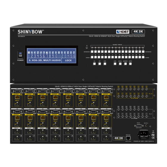
- Page 1 SB-5669CK 16x16 HDMI & HDBaseT - UHD 4K2K Matrix Routing Switch ™ w/ Full EDID Management/Learning...
-
Page 2: Safety Information
SAFETY INFORMATION To ensure the best results from this product, please read this manual and all other documentation before operating your equipment. Retain all documentation for future reference. Follow all instructions printed on unit chassis for proper operation. To reduce the risk of fire, do not spill water or other liquids into or on the unit, or operate the unit while standing in liquid. Make sure power outlets conform to the power requirements listed on the back of the unit. -
Page 3: Table Of Contents
1080p up to 98 feet (30M) & 4K2K up to 66 feet (20M). COPYRIGHT NOTICE Supports UXGA/WUXGA/DVI 1920x1200 resolution to any HD displays. The SB-5669CK has (16) HDMI connector Inputs and No part of this document may be reproduced, transmitted, (16) HDBaseT &... -
Page 4: Features
* The Switcher will remember that last state during a power cycle. When power is removed and resorted, the last configuration will be invoked. PACKAGE CONTENTS Check that you have the following components; • SB-5669CK Matrix Switcher • RS-232 V2.0 / Ethernet V2.0 Protocol Instructions • Master wireless IR Remote Control (SW-5669) •... -
Page 5: Specifications
SPECIFICATIONS SPECIFICATIONS • Type of HDMI Switcher: (16) HDMI Inputs to (16) HDMI & (16) HDBaseT Outputs Matrix Switcher ™ • HDMI Support: HDMI 4K2K, 1080p-@60Hz, H36-bit Deep color, 3D of HDMI V1.4 formats • HDBaseT Support: HDMI digital signals, bi-directional IR and RS-232 over single CATx (6/6a/7) cable ™... -
Page 6: Front Panel
FRONT PANEL FRONT PANEL 1. POWER ON SWITCH: The power switch turns the unit on and off. The LCM will illuminate blue to indicate the switcher is ON and receiving power. The switcher will remember the last setting during a power cycle. When power is removed and resorted, the last configuration will be evoked. - Page 7 FRONT PANEL FRONT PANEL 9. FUNCTION KEY - ALL: Disables (mutes) video on all destinations OR assigns the same source to all destinations. Option 1 - Press ALL followed by OFF button. The display will show ”0” to indicate none of the destinations are assigned a video source.
- Page 8 FRONT PANEL FRONT PANEL 13. FUNCTION KEY - MEMORY: The system will show stored presets, up to a total of 32. Presets are stored in local memory using Source keys 1 thru 16 or Destination keys 1 thru 16 as the memory preset location. - Configure desired matrices.
- Page 9 FRONT PANEL FRONT PANEL 16. SELECT (7) EMBEDDED EDID MODES: Used to display/change current EDID mode. - Press EDID to select new EDID mode. - Press SOURCE row #1 or #2. Select (7) Embedded EDID modes. - Press ENTER to ready memory location. - Or press EDID again to cancel operation.
-
Page 10: Back Panel
BACK PANEL BACK PANEL 1. DC POWER INLET: POWER SOCKET: The switcher is fitted with a AC power plug input Connector Type: IEC 60320 C13 connector. Ensure that the plug used is of an approved type and is of sufficient current carrying connector capacity with the correct voltage and connector polarity. - Page 11 BACK PANEL BACK PANEL 5. INPUTS - 1 ~ 16 HDMI: HDMI CONNECTOR: Connects a HDMI signal source to the HDMI Type A SMD 19pin Input. The HDMI port supports HDMI with embedded audio and female socket connector. DVI with AUX audio sources. Note: With the proper adapters, the switcher can be used with DVI digital video If you remove the HDMI screw posts, you must use the provided...
- Page 12 BACK PANEL BACK PANEL 7. OUTPUT - 1 ~ 16 HDBASET (TRANSMITTER): HDBASET TRANSMITTER CONNECTOR: ™ ™ Sends (16) HDMI (16) and control signals via (16) HDBaseT Transmitters to link (16) RJ-45 jack 8P8C female socket. ™ external HDBaseT Receivers. ™...
- Page 13 BACK PANEL BACK PANEL 8. HDBASET RS-232: 1~16 CONNECTION: REMOTE PORT: ™ (16) RS-232 control DB-9pin Female connector ports allow for interfacing to a PC. Controls I/O via the switchers HDBaseT Transmitters to (16) rooms each via the D-Bub 9pin ™...
-
Page 14: I/O Transmission & Cable Extension Lengths
HDBASET I/O TRANSMISSION & CABLE EXTENSION LENGTHS ™ HDBASET I/O TRANSMISSION ™ Category cable lengths via Switcher and HDBaseT Receiver. ™ Cable Type Pixel clock rate CAT5e CAT6 CAT6 Resolution (MHz) (70M) (100M) (100M) 1024x768@60Hz 65.00 MHZ 1280x720p@60Hz 73.84 MHZ 1920x1080i@60Hz 74.25 MHZ 1280x1024@60Hz... -
Page 15: Remote Control
REMOTE CONTROL Before making any connections observe the following: • Ensure the mains voltage supply matches the label on the supplied plug- Pack (+/- 10%). • Ensure that the power switch is OFF. • Ensure that all system grounds (earth) are connected to a common point. •... -
Page 16: Ir Remote Code List
REMOTE PROTOCOL COMMANDS IR REMOTE CUSTOM AND DATA CODES (NEC Standard) HOW TO SETUP IR CODES : CUSTOM CODE : 5BA4 POWER ON : 5BA4 A15E OFF : 5BA4 B14E EDID : 5BA4 B748 POWER OFF : 5BA4 A25D RECALL : 5BA4 B24D LOCK : 5BA4 B54A ALL : 5BA4 B04F ENTER : 5BA4 B34C... - Page 17 REMOTE PROTOCOL COMMANDS Let Destination # 4 show the signal from Source #1~16 Let Destination # 5 show the signal from Source #1~16 Let Destination # 6 show the signal from Source #1~16 Press Destination# > Source# The IR Data Code list : Press Destination# >...
- Page 18 REMOTE PROTOCOL COMMANDS Let Destination # 13 show the signal from Source #1~16 Let Destination # 14 show the signal from Source #1~16 Let Destination # 15 show the signal from Source #1~16 Press Destination# > Source# The IR Data Code list : Press Destination# >...
-
Page 19: Room Ir Remote Codes
REMOTE CONTROL ROOM IR REMOTE CONTROL #01 ~ #09 CUSTOM CODE AND DATA CODES IR CUSTOM AND DATA CODES (NEC Standard) PRESS Number To Select SOURCE CUSTOM CODE : 42BD IR-01 DATA CODE: IR-02 DATA CODE: IR-03 DATA CODE: SOURCE #1 : 42BD 00FF SOURCE #1 : 42BD 10EF... - Page 20 REMOTE CONTROL ROOM IR REMOTE CONTROL #10 ~ #16 CUSTOM CODE AND DATA CODES IR CUSTOM AND DATA CODES (NEC Standard) PRESS Number To Select SOURCE CUSTOM CODE : 42BD IR-10 DATA CODE: IR-11 DATA CODE: IR-12 DATA CODE: SOURCE #1 : 42BD 906F SOURCE #1 : 42BD A05F...
-
Page 21: Rs-232 / Ethernet Protocol
RS-232 & ETHERNET SERIAL INTERFACE RS-232 SERIAL INTERFACE CONNECT a PC or CONTROL SYSTEM. VERSION COMPATIBLE V2.0.1 For a complete list of commands, please reference external document extended RS-232 Protocol Instruction Manual. Example of the commanded string to route Input 3 to Output 4: OUTPUT04 03; RS-232 CONFIGURATION RS-232 cable is a straight thru cable and not null-modem Definition... -
Page 22: Edid Function
EDID FUNCTION SYSTEM RESET FUNCTION FOR MATRIX SWITCH SYSTEM RETURN TO FACTORY DEFAULTS SYSTEM RESET Switch Return To Factory default How to SYSTEM RESET RESET To the FACTORY DEFAULT. RECALL > OFF > ENTER Press Press RECALL button: The LCM will show the current stored presets status. Press OFF button : The LCM will show “SYSTEM RESET”. - Page 23 EDID FUNCTION (7) EDID MODE : EDID MANAGEMENT FOR HDMI MATRIX SWITCH Mode 1. FSS (Fast Speed Start) Fast Speed Start mode shortens the startup time of the switcher. Selecting this mode does not force the EDID setup to be cancelled. Users may first select one EDID mode from mode 2 to 7, and then select mode 1 for fast speed start.
- Page 24 EDID FUNCTION FAST SPEED START EDID MODE EDID status To view the current EDID status Step 1. Press EDID button The button will flash blue and the display will show the current Embedded EDID Status. Step 2. Press EDID button To exit.
- Page 25 EDID FUNCTION LEARNING EDID MODE-1 FUNCTION FOR HDMI MATRIX SWITCH LEARNING HDMI/HDBaseT EDID Learning HDMI or HDBaseT from Destination to Source ™ ™ Learning HDMI EDID Single HDMI-Destination to Multiple / All Sources EDID > DESTINATION > SOURCE > ENTER Press Press EDID >...
- Page 26 EDID FUNCTION Press: 4. Press ENTER to confirm changes. The LCM will return to the default screen selected switch routing status. Enter button NOTE: The already learned EDID cannot be modified. You can only rebuild a new Learning EDID. For example; When the Source has “Learned” the EDID data from a destination, It will save that EDID information into EPROM and the EDID data cannot change.
- Page 27 EDID FUNCTION EDID FUNCTION : LEARNING EDID MODE-2 - MULTIPLE TO ALL Learning Mode-2 Multiple Destinations to ALL Sources Key Press Sequence: EDID Destination 1 thru 16 Enter The EDID for HDMI or HDBaseT™ has been learned from the Destination port to the Source port. Press: 1.
-
Page 28: Ir Extender
IR EXTENDER 1. SB-100 IR 300M Receiver Switcher IR EXT. In Cable (3C) IR Receiver (SB-100) Distance: Max.300M IR PN#: SB-XXXX R oHS /95/E C INP UT R S -232 IR E XT. in DC 12V IR Rx RS - 232 IR EXT . - Page 29 IR EXTENDER 1. SB-101 IR 300M Transmitter Device Cable (3C) IR Transmitter (SB-101) IR out CAT6/6a/7 DC 12V IR in R oHS /95/E C IR Tx From OUTPUT Receiver Receiver SB-101 SB-101 IR Transmitter Set SB-101 Maximum Distance ~ 984 feet (300M) 2.
-
Page 30: Typical Applications
INSTALLING DIAGRAM Samples connection : 1. Using IR External or RS-232 command to control Switcher SB-5669CK via a PC or use extender Receiver (SB-100) to transmit the SB-5669CK’s IR signal to control switch I/O. 2. Switch control via Bi-Directional IR, RS-232 and Ethernet. - Page 31 TYPICAL APPLICATION - IR TRANSMITTER / RECEIVER INSTALLING DIAGRAM Samples Connection : 1. Using SB-5669CK HDBaseT Transmitter to transmit the IR signal via a HDBaseT Receiver (SB-6335R) via Transmitters (SB-101) ™ ™ and IR Receiver (SB-100) to control a projector.
- Page 32 TYPICAL APPLICATION - CONTROL SOURCE VIA HDBASET™ INSTALLING DIAGRAM Samples connection : 1. Using SB-5669CK HDBaseT Transmitter to transmit the IR signal via a HDBaseT Receiver (SB-6335R) and IR Transmitters (SB- ™ ™ 101) to control Satellite Receiver. NOTE: 1. IR Control Satellite Receiver Over HDBaseT ™...
- Page 33 TYPICAL APPLICATION - CONTROL VIA HDBASET™ RS-232 INSTALLING DIAGRAM Samples connection : 1. Using SB-5669CK HDBaseT Transmitter to extend RS-232 commands to HDBaseT Receiver (SB-6335R) to control a projector via ™ ™ a PC RS-232 serial interface. NOTE: 1. IR Control Projector Over HDBaseT Extender: SB-5669CK ™...
-
Page 34: Hdbaset ™ Application
HDBASET APPLICATION - TRANSMITTER & RECEIVER ™ APPLICATION HDBaseT Matrix Switcher using HDBaseT Transmitters & Receiver (Sold separately). ™ ™ Supports HDBaseT Extender by Transmitter and Receiver via HDBaseT CATx (6/6a/7) cable. ™ ™... - Page 35 HDBASET APPLICATION ™ APPLICATION Optional 19 inch Rack Mount Bracket for SB-6335T and/or SB-6335R: Complete 19 inch 4U rack mount of SB-6069 Install Application: SB-6335T/R SB-6069 (optional) SB-6335T/R 19 INCH 4U-10P RACK MOUNT Model No.: #4U-10p-M130MM SB-6335T/R 4U Ear mount pairs Parts No.: MEER6069ER13000 Model No.: #4U-10p-M130MM-COV SB-6335T/R 4U Ear mount pairs...
- Page 36 HDBASET APPLICATION ™ RACKMOUNT (OPTIONAL) SB-6075A: SB-6335T/R 19 INCH 1RU-1UNIT RACK MOUNT Model No.: #1U-1p-L440-44MM SB-6075B: SB-6335T/R 19 INCH 1RU-2UNIT RACK MOUNT Model No.: #1U-2p-L440-44MM SB-6069: SB-6335T/R 19 INCH 4U-10P RACK MOUNT Model No.: #4U-10p-L130MM SB-6335T/R 4U Ear mount pairs Parts No.: MEER6069ER13000...
-
Page 37: Limited Warranty
LIMITED WARRANTY PLEASE READ THE FOLLOWING TERMS AND CONDITIONS CAREFULLY BEFORE USING THIS HARDWARE, COMPONENTS AND SOFTWARE PROVIDED BY, THROUGH OR UNDER SHINYBOWUSA, INC (COLLECTIVELY, THE “PRODUCT”). By using installing or using the Product, you unconditionally signify your agreement to these Terms and Conditions. If you do not agree to these Terms and Conditions, do not use the Product and return the Product to SHINYBOWUSA, Inc. - Page 38 THIS PAGE IS INTENTIONALLY LEFT BLANK.
- Page 39 THIS PAGE IS INTENTIONALLY LEFT BLANK.
- Page 40 122 Rose Ln. Suite 303 | Frisco, Texas 75034 1-877-SHINY-USA 1-877-744-6987 1-972-377-2508 sales@shinybowusa.com www.shinybowusa.com...
Need help?
Do you have a question about the SB-5669CK and is the answer not in the manual?
Questions and answers