Table of Contents
Advertisement
Quick Links
Download this manual
See also:
Instruction Manual
INSTRUCTION MANUAL
M ULT I MEDI A AU DIO A N D VI SU A L
MODEL : SB-5669CK
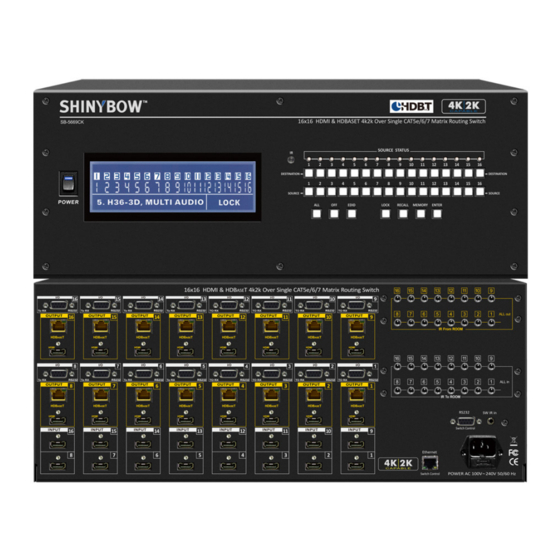
16x16 HDMI & HDBaseT 4K2K MATRIX ROUTING SWITCHER
16x16 HDMI & HDBaseT 4K2K Over Single CAT5e/6/7
Matrix Routing Switch
HDMI-HDBaseT 4k2k Matrix Routing Switch Series
Thank you for purchasing the SB-5669CK HDMI-HDBaseT Matrix Switcher. You will fi nd this unit easy to install
and highly reliable but it is essential that you read this manual thoroughly before attempting to use 16x16 HDMI-
HDBaseT Matrix switcher.
Advertisement
Table of Contents

Subscribe to Our Youtube Channel
Related Manuals for Shinybow USA SB-5669CK


Summary of Contents for Shinybow USA SB-5669CK
- Page 1 HDMI-HDBaseT 4k2k Matrix Routing Switch Series Thank you for purchasing the SB-5669CK HDMI-HDBaseT Matrix Switcher. You will fi nd this unit easy to install and highly reliable but it is essential that you read this manual thoroughly before attempting to use 16x16 HDMI-...
- Page 2 SAFETY INFORMATION To ensure the best results from this product, please read this manual and all other documentation before operating your equipment. Retain all documentation for future reference. Follow all instructions printed on unit chassis for proper operation. To reduce the risk of fi re, do not spill water or other liquids into or on the unit, or operate the unit while standing in liquid. Make sure power outlets conform to the power requirements listed on the back of the unit.
-
Page 3: Table Of Contents
UXGA/WUXGA/DVI 1920x1200 resolution to any HD displays. The We reserve the right to make improvements to this document and/ SB-5669CK has 16x HDMI connector Input and 16x HDBaseT & or product at any time and without notice. 16xHDMI output, effectively making this an 16 in x32 out switcher (same signal on both outputs). -
Page 4: Package Contents
PACKAGE CONTENTS PACKAGE CONTENTS Check that you have the following components; • SB-5688CK Matrix Switcher • Master wireless IR Remote Control (SW-5669) • 16 each; Individual wireless IR Control (HD-69CK-IR01~IR16) • 19 inch Ear mount bracket (Part # 4U-440L) • SB-101 IR Extender distance ~984 feet (300M) Transmitter set. •... -
Page 5: Features
FEATURES FEATURES Based on HDBaseT; bi-directional IR and RS-232 interface. Full resolution HD Video, all HDBaseT signals over single category cable (CAT6/6a/7). • Enables switching of (16)x HDMI digital source devices to (16)x HDMI devices and (16)x HDBaseT • Transmitter output to (32)x destinations •... -
Page 6: Specifications
SPECIFICATIONS SPECIFICATIONS • Type of HDMI Switcher: 16x HDMI inputs To 16x HDMI & 16x HDBaseT Outputs Matrix Switcher. • HDMI Support: HDMI 4K2K, 1080p-@60Hz, H36-bit Deep color, 3D of HDMI V1.4 formats • HDBaseT Support: HDMI digital signals, bi-directional IR and RS-232 over single CATx(6/6a/7) cable •... -
Page 7: Front Panel
FRONT PANEL FRONT PANEL 1. POWER ON SWITCH The power switch turns the unit on and off. The LCM will illuminate blue to indicate the switcher is ON and receiving power. The switcher will remember the last setting during a power cycle. When power is removed and resorted, the last confi guration will be evoked. 2. - Page 8 FRONT PANEL FRONT PANEL 8. FUNCTION KEY - ALL Disables (mute) video on all destinations OR assign the same source to all destinations. Option 1 - Press ALL followed by OFF button. The display will show ”0” to indicate none of the destinations are assigned a video source.
- Page 9 FRONT PANEL FRONT PANEL 12. FUNCTION KEY - MEMORY The system will show store presets, up to a total of 32. Presets are stored in local memory using Source keys 1 thru 16 or Destination keys 1 thru 16 as the memory preset location. - Confi...
- Page 10 FRONT PANEL FRONT PANEL 16. FUNCTION KEY - EDID (1) Used to display change current EDID mode. - Press EDID to select new EDID mode or select - Press SOURCE row #1 or #2 Select EDID modes. - Press ENTER to ready memory location. - Or press EDID again to cancel operation.
-
Page 11: Rear Panel
BACK PANEL BACK PANEL 1. DC POWER INLET: Power Socket: The Switcher is fi tted with a AC power plug input connector. Connector Type : IEC 60320 C13 Ensure that the used is of an approved type and is of suffi cient current carrying connector capacity with the correct voltage and connector polarity. - Page 12 BACK PANEL BACK PANEL 5. INPUTS - 1 ~ 16 HDMI: HDMI Connector: HDMI Type A SMD 19pin Female Connect an HDMI signal source to this Input. This HDMI port socket connector. supports HDMI with embedded audio and DVI with AUX audio Note: With the proper adapters, the switcher sources.
- Page 13 BACK PANEL - HDBaseT I/O BACK PANEL 7. OUTPUT - 1 ~ 16 HDBaseT (Transmitter): HDBaseT Transmitter Connector: 16x RJ-45 Jack To send 16 HDMI and control signals via Switcher 16x HDBaseT 8P8C Female socket. Transmitters to link 16x external HDBaseT Receiver. Switcher used 16x HDBaseT Transmitter Output #1 ~ Output Link LED : solid = valid link #16 with PoE (optional) RJ-45 via CATx(6/6a/7) category cable.
- Page 14 BACK PANEL BACK PANEL 8. HDBaseT RS-232: Remote port: DB-9pin Female connector 1~8 & 9 ~16 CONNECTION: 16x RS-232 control port to allow for interfacing to a PC. Controls I/O via Switcher HDBaseT Transmitter 16 Rooms each via this D-Bub 9pin Female socket for serial RS-232 control. 9.
-
Page 15: Hdbaset I/O Transmission & Cable Extension Lengths
HDBaseT I/O TRANSMISSION & CABLE EXTENSION LENGTHS HDBaseT I/O TRANSMISSION RS-232 Cable Pins out PC 232 PINS DB-9P , MALE plug HDBaseT Transmitter SB-6335T RS-232 PINS OUT DB-9P , FEMALE socket HDBaseT Receiver SB-6335R RS-232 PINS OUT DB-9P , FEMALE socket Category cable lengths via Switcher and HDBaseT Receiver. -
Page 16: Remote Control
REMOTE CONTROL Before making any connections to the switcher, observe the following: • Ensure the mains voltage supply matches the label on the supplied plug- Pack (+/- 10%). • Ensure that the power switch is OFF. • Ensure that all system grounds (earth) are connected to a common point. •... - Page 17 IR REMOTE CODE LIST IR REMOTE CUSTOM AND DATA CODES (NEC STANDARD) HOW TO SETUP IR CODES : CUSTOM CODE : 32CD POWER ON : 32CD A15E OFF : 32CD B14E EDID : 32CD B748 POWER OFF : 32CD A25D RECALL : 32CD B24D LOCK : 32CD B54A ALL : 32CD B04F...
- Page 18 IR REMOTE CODE LIST Let Destination # 7 show the signal from Source #1~16 Let Destination # 8 show the signal from Source #1~16 Let Destination # 9 show the signal from Source #1~16 Press Destination# > Source# The IR Data Code list : Press Destination# >...
- Page 19 ROOM IR REMOTE CODE #01 ~ #04 ROOM IR REMOTE CONTROL #01 ~ #04 CUSTOM CODE AND DATA CODES IR CUSTOM AND DATA CODES (NEC Standard) PRESS Number To Select SOURCE CUSTOM CODE : 32CD IR-01 DATA CODE: IR-02 DATA CODE: SOURCE #1 : 32CD 00FF...
- Page 20 ROOM IR REMOTE CODE #05 ~ #08 ROOM IR REMOTE CONTROL #05 ~ #08 CUSTOM CODE AND DATA CODES IR CUSTOM AND DATA CODES (NEC Standard) PRESS Number To Select SOURCE CUSTOM CODE : 32CD IR-05 DATA CODE: IR-06 DATA CODE: SOURCE #1 : 32CD 40BF...
- Page 21 ROOM IR REMOTE CODE #09 ~ #12 ROOM IR REMOTE CONTROL # 09 ~ #12 CUSTOM CODE AND DATA CODES IR CUSTOM AND DATA CODES (NEC Standard) PRESS Number To Select SOURCE CUSTOM CODE : 32CD IR-09 DATA CODE: IR-10 DATA CODE: SOURCE #1 : 32CD 807F...
- Page 22 ROOM IR REMOTE CODE #13 ~ #16 ROOM IR REMOTE CONTROL #13 ~ #16 CUSTOM CODE AND DATA CODES IR CUSTOM AND DATA CODES (NEC Standard) PRESS Number To Select SOURCE CUSTOM CODE : 32CD IR-13 DATA CODE: IR-14 DATA CODE: SOURCE #1 : 32CD C03F...
-
Page 23: Edid Functions
EDID FUNCTION EDID FUNCTION SETUP EDID Setup To Change the EDID Setup Step 1. Press the EDID button The display will show the currently selected EDID mode Step 2. Press SOURCE #1 or #2 button row The button will fl ash blue and the display will show the current Embedded EDID Status. - Page 24 EDID FUNCTION Mode 4. H36-3D-M (1080p-36 bits) Audio Support: PCM 2CH Mode 5. H36-3D (1080p-36 bits) Audio Support: MAT(MLP) 7.1CH, PCM2CH, One Bit Audio 2CH, AC-3 5.1CH, DTS5.1CH, PCM7.1CH, Dolby Digital + 7.1CH, DTS-HD 7.1CH Mode 6. 4K2K (24/30Hz) HDMI Support : 4K2K-3D, PCM 2CH (3840x2160-24/30Hz) Audio Support : PCM 2CH Mode 7.
- Page 25 EDID FUNCTION Learning EDID Single to Single Example : Learn Destination #8 EDID To Source #5. Step 1. Press EDID button The button will fl ash blue and the display will show the current Embedded EDID Status. Step 2. Press the Destination #12 button row Copy the Destination #12 Display EDID.
- Page 26 EDID FUNCTION EDID FUNCTION : LEARNING Learning EDID Single Destination to Single Source EDID Destination 1 thru 16 Source 1 thru 16 Enter Copy the EDID of a single destination device and pass it to a single source. The source device will output video and audio according to the EDID of the destination.
- Page 27 EDID FUNCTION COMPARISON TABLE Function Note Learning Let the source device(s) learn the EDID When a source devices has “learned” the EDID information of a destination Mode from a single source and output video device, the switcher will save that EDID into EPROM and the stored EDID and audio accordingly.
-
Page 28: Typical Application
INSTALLING DIAGRAM Samples connection : 1. Using IR External or RS-232 command to control Switcher SB-5669CK via a PC or use extender Receiver (SB-100) to transmit the SB-5669CK’s IR signal to control switch I/O. 2. Switch control via Bi-Directional IR, RS-232 and Ethernet. - Page 29 TYPICAL APPLICATION IR Transmitter / Receiver INSTALLING DIAGRAM Sample connection using SB-5669CK’s HDBaseT Transmitter and a HDBaseT Receiver (SB-6335R) via IR Transmitters (SB-101) and IR Receiver (SB-100) to control a projector. NOTE: 1. Using IR control Projector Over HDBaseT Extender: HDBaseT Transmitter : SB-5669CK HDBaseT Tx.
- Page 30 TYPICAL APPLICATION Control Source via HDBaseT INSTALLING DIAGRAM Sample connection using SB-5669CK HDBaseT Transmitter to transmit the IR signal via a HDBaseT Receiver (SB-6335R) and IR Transmitters (SB-101) to control Satellite Receiver. NOTE: 1. IR Control Satellite Receiver Over HDBaseT Extender via...
- Page 31 TYPICAL APPLICATION - Control Via HDBaseT RS-232 INSTALLING DIAGRAM Sample connection using SB-5669CK HDBaseT Transmitter to extend RS-232 commands to HDBaseT Receiver (SB-6335R) To control a projector via a PC RS-232 serial interface. NOTE: 1. IR Control Projector Over HDBaseT Extender: SB-5669CK HDBaseT Transmitter / SB-6335R HDBaseT Receiver 2.
-
Page 32: Ir Extender
IR EXTENDER IR RECEIVER: 1. SB-100 IR 300M Receiver Device Cable (3C) IR Receiver (SB-100) R oHS /95/E C INP UT R S -232 IR E XT. in DC 12V IR Rx RS - 232 IR EXT . SB-100 SB-100 IR Receiver Set SB-100 Maximum Distance ~ 984 feet (300 meters) 2. - Page 33 IR EXTENDER IR EMITTER: 1. SB-101 IR 300M Transmitter Device Cable (3C) IR Transmitter (SB-101) IR out CAT6/6a/7 DC 12V IR in R oHS /95/E C IR Tx From OUTPUT Receiver Receiver SB-101 SB-101 IR Transmitter Set SB-101 Maximum Distance ~ 984 feet (300 meters) 2.
-
Page 34: Ethernet Protocol
ETHERNET SERIAL INTERFACE ETHERNET SERIAL INTERFACE CONNECT A PC OR CONTROL SYSTEM. VERSION COMPATIBLE V2.0 For a complete list of commands, please reference external document extended Ethernet Protocol Instruction Manual. ETHERNET SERIAL INTERFACE Pin Ethernet Reference TXOP TX + TXON TX - RXIP RX +... -
Page 35: Rs-232 Protocol
RS-232 SERIAL INTERFACE RS-232 SERIAL INTERFACE CONNECT A PC OR CONTROL SYSTEM. VERSION -2.0 COMPATIBLE RS-232 SERIAL INTERFACE RS-232 Defi nition -------- Not used Transmitter Receiver -------- Not used Ground -------- Not used -------- Not used -------- Not used -------- Not used RS-232 PROTOCOL COMMANDS (RS-232 Control driver V2.0.1) The ShinybowUSA switcher can be controlled via the RS-232 serial control port to allow for interfacing to a PC, or similar third party control... -
Page 36: Limited Warranty
LIMITED WARRANTY PLEASE READ THE FOLLOWING TERMS AND CONDITIONS CAREFULLY BEFORE USING THIS HARDWARE, COMPONENTS AND SOFTWARE PROVIDED BY, THROUGH OR UNDER SHINYBOWUSA, INC (COLLECTIVELY, THE “PRODUCT”). By using installing or using the Product, you unconditionally signify your agreement to these Terms and Conditions. If you do not agree to these Terms and Conditions, do not use the Product and return the Product to SHINYBOWUSA, Inc. - Page 37 M ULT IM EDI A AUDIO AN D V IS UA L 122 Rose Ln. Suite 303 | Frisco, Texas 75034 1-877-SHINY-USA 1-877-744-6987 1-972-377-2508 sales@shinybowusa.com www.shinybowusa.com...
Need help?
Do you have a question about the SB-5669CK and is the answer not in the manual?
Questions and answers