Table of Contents
Advertisement
Quick Links
KEY FEATURES
• High output line array element
• Compact size, very good output-to-weight ra o
• High quality, low compression, low distor on HF driver
• Very stable horizontal coverage
INTRODUCTION
The AX2065A Ver cal Line Array element is designed for a wide range of sound reinforcement applica ons where a fl exible and easy to use ver cal
array systems is needed. The AX2065A has been designed both for rental live sound applica ons and for fi xed installa ons and has been engineered
and eliminates the "boxy" mid-bass sound commonly obtained from regular bassrefl ex enclosures.
The AX2065A is processed by 40bit, 96kHz fl oa ng point CORE DSP and powered by DA SERIES digital
power modules, a new genera on of CLASS D power amplifi er with digitally-controlled SMPS. The
DA module employed for powering the AX2065A delivers in an ultra-compact package a maximum
power of 2000W and each AX2065A is able to power an addi onal passive AX2065P module through
the available power output on the back panel. This feature will allows to assemble very compe
hybrid solu ons both for rental and installa on applica ons.
TECHNICAL SPECIFICATION
Acous cal
System type
Low frequency transducer
High frequency transducer
Frequency response (±3 dB)
Horizontal Coverage Angle
Ver cal Coverage Angle
Maximum Peak SPL @ 1m
Electrical
Input Impedance
Input Sensi vity
Signal Processing
Direct access Controls
* Nominal consump on is measured with pink noise with a crest factor of 12
dB, this can be considered a standard music program.
revision 2014-11-10
USER MANUAL
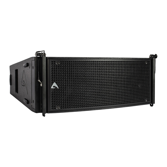
AX2065A
ac ve ver cal array loudspeaker
for the simplest use possible but without sacrifi cing anything in sound quality and performance.
The high frequency range is reproduced by a low-distor on compression driver, equipped with very light-weight
Titanium diaphragms and a special new suspension design for
very natural sound. A transmission line wave-forming waveguide
has been used to load the HF driver, in order to provide a detailed
and natural sound and to achieve a long-distance HF projec ng
capacity.
The two 6.5" woofers are back loaded by a short hybrid
transmission line that minimizes the eff ect of the box resonances
Line Array Element
Short Transmission Line LF Back Loading
Acous c Transmission Line HF Waveguide
Two 6.5" (165 mm), 1.5" (38 mm) aluminium
voice coil, 16Ω each, paralleled
One 1.4" driver, 2.5" (64 mm) edgewound
voice coil, tanium diaphragm,
8Ω each, paralleled
80 Hz – 18 kHz (Processed)
110° (-6 dB)
12° (-6 dB)
129 dB
20 kΩ balanced
+4 dBu / 1.25 V
CORE processing, 96kHz / 40bit fl oa ng
point SHARC DSP, 24 bit AD/DA converters
4 Presets: Standard, Long Throw, Down Fill-
Single Box, User.
Network Termina on, GND Link
• Transmission Line back loading for clean mid-bass reproduc on
• Natural sound Transmission Line HF projec on wave-forming device
• 96KHz / 40 bit fl oa ng point CORE processing with PRONET remote control
• Digitally controlled Class D amplifi er module with SMPS
Remote Controls
Network protocol
Amplifi er Type
Output Power
Mains Voltage Range (Vac)
Mains Connector
Consump on*
IN / OUT Connectors
IN / OUT Network Connectors
Mechanical
Width
Height
Depth
Taper angle
Construc on
Paint
Suspension system
Front Suspension
Back Suspension
Net Weight
ve
PRONET control so ware
CANBUS
Class D with Variable Switching Frequency
and SMPS
2x 1000 W
230 V~ ±15% or 115 V~ ±15% 50/60 Hz
PowerCon® (NAC3MPA + NAC3MPB)
700 W (nominal) 1700 W (max)
Neutrik XLR-M / XLR-F / Speakon NL4MP
ETHERCON® (NE8FAV)
583 mm (22.95")
244 mm (9.60")
481 mm (18.93")
5°
15 mm, reinforced Phenolic Birch
High resistance, water based paint
Aluminium Fast Link structure with ¼ Fast Pin
High Strength Steel with ¼ Fast Pin
22.5 Kg (49.6 lbs.)
Advertisement
Table of Contents

Related Manuals for Axiom AX2065A


Summary of Contents for Axiom AX2065A
-
Page 1: User Manual
INTRODUCTION The AX2065A Ver cal Line Array element is designed for a wide range of sound reinforcement applica ons where a fl exible and easy to use ver cal array systems is needed. The AX2065A has been designed both for rental live sound applica ons and for fi xed installa ons and has been engineered for the simplest use possible but without sacrifi... - Page 2 Carrying Case for 4 box unit USB2CAN PRONET network converter NAC3FCA Neutrik Powercon® BLUE PLUG KPTSW215 Fly bar for Axiom AX2065 and SW215 Loudspeakers NAC3FCB Neutrik Powercon® WHITE PLUG KPTAX2065 Fly bar for Axiom AX2065 only NE8MCB Neutrik Ethercon PLUG...
- Page 3 TERMINATE - In a PRONET network the last loudspeaker device must be terminated (with an inner load resistance) especially in a long run cabling: press this switch if you want to terminate the unit. POWER OUT - AX2065A is able to power an addi onal passive AX2065P module through the available power output on the back panel.
- Page 4 POWER AMPLIFIERS The AX2065A is powered by DA SERIES digital power modules, a new genera on of CLASS D power amplifi er with digitally-controlled SMPS. The innova ve technology used for these amplifi ers (including also the use of a variable switching frequency) off ers performances at the top of the range, such as a superior sound defi...
- Page 5 TOP BOX DOWN FILL BOXES: the power level in the proximity of the stage is higher, as well as the high frequency level. DOWN FILL BOX AX2065A - PRESET RESPONSE LONG THROW STANDARD SINGLE/DOWNFILL PRESET USING EXAMPLE In order to op mize the array performances for this specifi c applica on, the PRESETS should be used in the following way.
- Page 6 Download the EASE Focus 2 app from the AXIOM website at h p://www.axiomproaudio.com/ clicking on downloads sec on of the product. Use the menu op on Edit / Import System Defi ni on File to import the fi le AXIOM_AX Series_v2_1.gll from the installa on Data folder, the detailed instruc ons to use the program are located in the menu op on Help / User’s Guide.
- Page 7 KPTSW215 FLY BAR FOR FLOWN ARRAY KPTSW215 FLOWN PINPOINT SINGLE PINPOINT FOR STRAIGHT SHACKLE Follow the sequence in the fi gure for fi xing the fl y bar at the fi rst box. Usually this is the fi rst step before li ing up the system. Be careful to insert properly all the locking pins (1)(2) and (3)(4) then the shackle (5) in the right holes as specifi...
- Page 8 Stacked installa on (KPTSW215 only) KPTSW215 STACKED ARRAY WARNING! • The ground where the KPTSW215 Fly bar serving as ground support is placed needs to be absolutely stable and compact. • Adjust the feet so to lie the bar perfectly horizontal. max splay angle 10°...
Need help?
Do you have a question about the AX2065A and is the answer not in the manual?
Questions and answers