Table of Contents
Advertisement
Quick Links
Advertisement
Table of Contents

Related Manuals for Axiom AX2065AV2


Summary of Contents for Axiom AX2065AV2
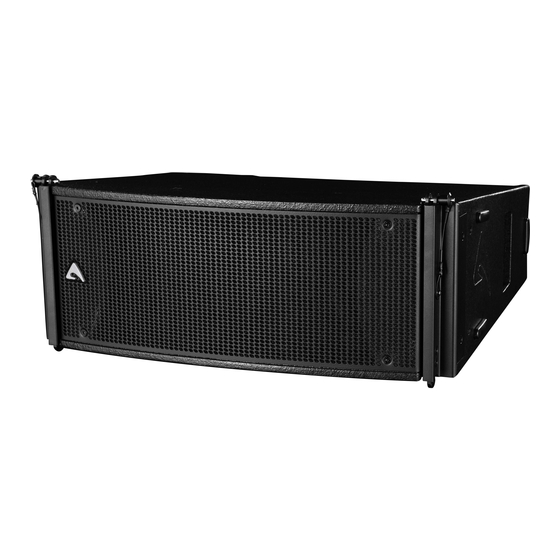
- Page 1 AX2065AV2 Active Vertical Array Loudspeaker USER MANUAL revision 2023-09-04...
-
Page 2: Important Safety Instructions
IMPORTANT SAFETY INSTRUCTIONS Watch for these symbols: The lightning flash with arrowhead symbol within an equilateral triangle is intended to alert the user to the presence of uninsulated “dangerous voltage” within the product’s enclosure, that may be of sufficient magnitude to constitute a risk of electric shock to persons. -
Page 3: Federal Communications Commission (Fcc) Statement
FEDERAL COMMUNICATIONS COMMISSION (FCC) STATEMENT This equipment has been tested and found to comply with the limits for a Class A digital device, pursuant to part 15 of the FCC Rules. These limits are designed to provide reasonable protection against harmful interference when the equipment is operated in a commercial environment. This equipment generates, uses, and can radiate radio frequency energy and, if not installed and used in accordance with the instruction manual, may cause harmful interference to radio communications. -
Page 4: Technical Specification
“boxy” mid-bass sound commonly obtained from regular bassreflex enclosures. The AX2065AV2 is processed by 40 bit floating point CORE2 DSP and powered by a high efficiency CLASS D amplifier module with a newly designed power supply equipped with PFC, which reduces the power consumption while enhancing reliability and consistency in all operating conditions. -
Page 5: Mechanical Drawing
Fly bar for Axiom AX2065 and SW215 Loudspeakers AXCASE06 Carrying Case for 4 box unit KPTAX2065 Fly bar for 6 MAX Axiom AX2065 Loudspeakers only NAC3FXXA-W-L Neutrik Powercon® BLUE PLUG AXFEETKIT Kit of 6pcs BOARDACF01 M10 foot for stacked installation NAC3FXXB-W-L Neutrik Powercon®... -
Page 6: Power Out
• Turn on each unit one a time starting from the latest unit. POWER OUT AX2065AV2 is able to power an additional passive AX2065P module through the available power output on the back panel. WARNING: connect a single AX2065P module only. -
Page 7: Preset Button
POWER OUT PIN 1+/1-: MF PIN 2+/2-: HF CONNECT ONLY AX2065P NETWORK IN/OUT These are a standard RJ45 CAT5 connectors (with optional NEUTRIK NE8MC RJ45 cable connector carrier), used for PRONET network transmission of remote control data over long distance or multiple unit applications. TERMINATE In a PRONET AX network the last device must be always terminated (with an inner load resistance): press this switch if you want to terminate the network on this unit. - Page 8 In this case some optional accessories are required: 1x KPAX265, 1x KP10, 1x DHSS10M20 for each system. KPAX265 Each AX2065AV2 box preset must be set as DOWN FILL/SINGLE BOX. KP010 DHSS10M20 PRESET USING EXAMPLE: INSTALLATION IN A THEATRE WITH BALCONY...
- Page 9 PRONET AX - OPERATION The AXIOM active loudspeaker devices can be connected in a network and controlled by the PRONET AX software. PRONET AX software has been developed in collaboration with sound engineers and sound designers, in order to offer an “easy-to- use”...
- Page 10 AFMG Technologies GmbH. It is based on the EASE GLL loudspeaker data file required for its use. The GLL file contains the data that defines the Line Array with regard to its possible configurations as well as to its geometrical and acoustical properties. Download the EASE Focus 3 app from the AXIOM website at https://www.axiomproaudio.com/ clicking on downloads section of the product.
- Page 11 The following examples shows how to operate correctly to link the loudspeaker box and to suspend or stack the whole system safely and surely, read these instructions with extreme attention: WARNING! CAREFULLY READ THE FOLLOWING INSTRUCTIONS AND CONDITION OF USE: •...
- Page 12 Pin locking and splay angles set up The figures below shows how to insert correctly the locking pin, always carefully check that each pin is fully inserted and locked in the correct position. Set up the splay angle between loudspeakers inserting the pin in the correct hole, please note that the inner holes in the hinge top are for even angles (2, 4, 6 etc.) while the outer holes are for the odd angles (1, 3, 5 etc.).
- Page 13 10:1, up to: • 6 AX2065 active or passive (flybar from 0° to 10°) • 8 AX2065AV2 + 8 AX2065P (flybar from 0° to 10°) • 12 AX2065AV2 (flybar from 0 to 10°) KPTAX2065 can NOT be used for stacked array.
- Page 14 Follow the sequence in the figure for fixing the fly bar at the first box. Usually this is the first step before lifting up the system. Be careful to insert properly all the locking pins (2)(3) and the shackle (5) in the right holes as specified by the aiming software. When lifting the system always proceed gradually step by step, paying attention to secure the fly bar to the box (and the box to the other boxes) before pulling up the system: this makes easier to insert properly the locking pins.
- Page 15 Follow the sequence in the figure for fixing the fly bar at the first box. Usually this is the first step before lifting up the system. Be careful to insert properly all the locking pins (2)(3) and the shackle (5) in the right holes as specified by the aiming software. When lifting the system always proceed gradually step by step, paying attention to secure the fly bar to the box (and the box to the other boxes) before pulling up the system: this makes easier to insert properly the locking pins.
-
Page 16: Stacked Installation
The optimal splay angles can be simulated using the EASE Focus 3 software. KPTSW215 STACKED ARRAY max splay angle 10° max splay angle 10° max splay angle 10° max splay angle 10° System: AXIOM AX Series Company: PROEL S.p.A. Label: AXIOM AX Series Position: X=0.00 m Y=0.00 m...
Need help?
Do you have a question about the AX2065AV2 and is the answer not in the manual?
Questions and answers