Fri-Jado STG7 P Installation Manual
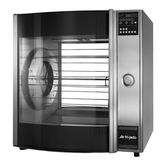
Gas fired rotisserie oven
Hide thumbs
Also See for STG7 P:
- Service manual (44 pages) ,
- Installation manual (22 pages) ,
- Installation manual (22 pages)
Table of Contents
Advertisement
Quick Links
INSTALLATION MANUAL
MODELS
Programmable controls
Gas types
This manual is prepared for the use of trained Service Technicians and should
This manual is not intended to be all encompassing. If you have not attended a
training for this product, you should read, in its entirety, the repair procedure
ments and skills required to perform the procedure. Procedures for which you
Reproduction or other use of this Manual, without the express written consent of
STG7 P GAS FIRED
ROTISSERIE OVEN
not be used by those not properly qualified. If you have attended a training
for this product, you may be qualified to perform all the procedures in this
you wish to perform to determine if you have the necessary tools, instru-
do not have the necessary tools, instruments and skills should be performed
STG7 P
G20/25
- NOTICE -
manual.
by a trained technician.
Fri-Jado, is prohibited.
Installation Manual STG7 P Gas form 9123689 rev. 11/2011
Model STG7 P Gas
Advertisement
Table of Contents

Subscribe to Our Youtube Channel
Related Manuals for Fri-Jado STG7 P


Summary of Contents for Fri-Jado STG7 P
- Page 1 Reproduction or other use of this Manual, without the express written consent of Fri-Jado, is prohibited. Installation Manual STG7 P Gas form 9123689 rev. 11/2011...
- Page 2 EMPTY PAGE Page 2 Installation Manual STG7 P Gas form 9123689 rev. 11/2011...
-
Page 3: Table Of Contents
Legs / castors ............................10 Tethering of the unit ........................... 11 Extraction of the rotisserie ........................12 Test run ..............................12 Instructions for operators ........................12 Maintenance ............................13 Installation drawings ..........................14 Installation Manual STG7 P Gas form 9123689 rev. 11/2011 Page 3... -
Page 4: General Technical Data
38 3/4 “ Depth 850 mm 33 1/2 “ Tools • Standard set of tools. • Metric wrenches, sockets and hex socket key wrenches. • VOM with AC current tester (any VOM with a sensitivity of at least 20,000 ohms per volt can be used). • Temperature tester. • Insulation value tester (Megger). • Toxicity meter. • Gas pressure meter. • TL 84919 Field Service Grounding Kit. Page 4 Installation Manual STG7 P Gas form 9123689 rev. 11/2011... -
Page 5: Installation Procedures
See pictures. Open door and remove the drawer. Lift the unit from pallet and put the unit in its place. Another possibility is to disassemble the pallet. For the pallet of the STG 7 follow the procedure on the photo. Installation Manual STG7 P Gas form 9123689 rev. 11/2011 Page 5... -
Page 6: Location
If use is to be made of a permanent connection, the connecting cable must be connected to a manual on/off switch that is installed near the unit in a clear visible manner. For a 1-phase 208 V ~ circuit with neutral, the unit must be connected according to the figure below. Page 6 Installation Manual STG7 P Gas form 9123689 rev. 11/2011... -
Page 7: Gas Connection
GAS INLET PRESSURE The inlet pressure has to be according the table on the next page. The pressure can be checked on the gas block with a pressure meter (see also gas block). Installation Manual STG7 P Gas form 9123689 rev. 11/2011 Page 7... -
Page 8: Gas Technical Data
Consumption Consumption type pressure pressure (Qn -Hi) (Qn -Hi) inch wc mbar inch wc mbar 14.5 0.89 cfm 1.51 m 14.5 1.01 cfm 1.71 m 14.5 0.32 cfm 0.55 m Page 8 Installation Manual STG7 P Gas form 9123689 rev. 11/2011... -
Page 9: Gas Consumption
You can use this measuring point also to check if the gas valves are opening. Coils for gas valves Inlet pressure Burner pressure Gas inlet Gas outlet Installation Manual STG7 P Gas form 9123689 rev. 11/2011 Page 9... -
Page 10: Flue Gas Analyser
130 °F dew point 54°C 713 °F Exhaust gas temp. 378°C °F Ambient temp. 23°C The 2 most important values are the CO2 percentage and the exhaust gas temperature. CO2% G 20/25 between 8.8 - 9.2% Exhaust gas between 698 - 788 °F (370 - 420 °C) LEGS / CASTORS Each rotisserie is furnished on 2 ” legs. A caster-equipped stand with convenient storage drawer is available. The rotisserie is mounted on top of the stand. Page 10 Installation Manual STG7 P Gas form 9123689 rev. 11/2011... -
Page 11: Tethering Of The Unit
The remaining open hole in the center of the tether bracket is to be used to secure one end of the tether (locally supplied chain, cable, etc.). The other end of the tether is to be secured to an anchoring point in the building struc- ture. Note: Length of tether must be shorter than the flexible conduit to make sure that during appliance movement, no stress is transmitted to the conduit. Warning: Following installation, check to confirm that, when the appliance is moved to the limits of the tether in each direction, no stress is transmitted to the electrical conduit. Installation Manual STG7 P Gas form 9123689 rev. 11/2011 Page 11... -
Page 12: Extraction Of The Rotisserie
• Programming and options. • Working of the unit. • Free space of unit for cooling of drive motor and blowers. • Run through the user manual. • Refer to the storyboard, training guide and laminated sheet with pre-programmed programs (only for Wall-mart). • Periodical maintenance: o Cleaning of fan plate every month. o Cleaning of fans on blower every month. • How to react for information or service calls. Page 12 Installation Manual STG7 P Gas form 9123689 rev. 11/2011... -
Page 13: Maintenance
• Check for gas leaks and/or bad connections of the gas supply inside and outside. • Check the gas burner. • Check the inlet pressure and re-adjust if necessary. For the correct value, see table page 8. • Measure the exhaust gas with a flue gas analyzer, see page 10. • Check the electrical supply. Installation Manual STG7 P Gas form 9123689 rev. 11/2011 Page 13... -
Page 14: Installation Drawings
Space between a rotisserie and a wall or ceiling Location for socket Gas connection *) length is measured from the point where the cables coms out of the unit Placing and connecting the STG 7 Page 14 Installation Manual STG7 P Gas form 9123689 rev. 11/2011... - Page 15 INSTALLATION DRAWINGS Placing and connecting the STG 7 on base Installation Manual STG7 P Gas form 9123689 rev. 11/2011 Page 15...
- Page 16 EMPTY PAGE Page 16 Installation Manual STG7 P Gas form 9123689 rev. 11/2011...
- Page 17 EMPTY PAGE Installation Manual STG7 P Gas form 9123689 rev. 11/2011 Page 17...
- Page 18 Fri-Jado Inc. • 180 Kehoe Blvd. • Carol Stream, Ill. 60188 • USA • tel. 630-784-3469 • fax 630-784-1650 • toll free 877-FRI-JADO • us.info@frijado.com • www.frijado.com...
Need help?
Do you have a question about the STG7 P and is the answer not in the manual?
Questions and answers