Table of Contents
Advertisement
Quick Links
SERVICE MANUAL
DELI MULTISSERIE
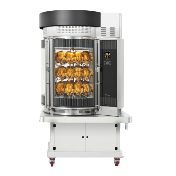
MODELS
Deli Multisserie with Grease Separator
Deli Multisserie with GS and condensor (shown).
Deli Multisserie with Grease Collector
Deli Multisserie with GC and condensor.
- NOTICE -
This manual is prepared for the use of trained Service Technicians and
should not be used by those not properly qualified. If you have attended
a trianing for this product, you may be qualified to perform all the proce-
dures in this manual.
This manual is not intended to be all encompassing. If you have not
attended a training for this product, you should read, in its entirety, the
repair procedure you wish to performto determine if you have the neces-
sary tools, instruments and skills required to perform the procedure.
Procedures for which you do not have the necessary tools, instruments
and skills should be performed by a trained technician.
Reproduction or other use of this Manual, without the express written
consent of Fri-Jado, is prohibited.
Service Manual Deli Multisserie form 9123560 rev. 02/2017
Page 1
Advertisement
Table of Contents
Troubleshooting

Related Manuals for Fri-Jado Deli Multisserie with Grease Separator


Summary of Contents for Fri-Jado Deli Multisserie with Grease Separator
- Page 1 SERVICE MANUAL DELI MULTISSERIE MODELS Deli Multisserie with Grease Separator Deli Multisserie with GS and condensor (shown). Deli Multisserie with Grease Collector Deli Multisserie with GC and condensor. - NOTICE - This manual is prepared for the use of trained Service Technicians and should not be used by those not properly qualified.
- Page 2 Table of Contents Page 2 Service Manual Deli Multisserie form 9123560 rev. 09/2017...
-
Page 3: Table Of Contents
Table of Contents Versions Version Issue date Remarks dd/mm/yy 0706 06/2007 First release 1112 6/1/2012 Significant overall update. 1201 13/1/2012 changes on pages 38,53,66,76 regarding addition of pcb of 3-way valve 1701 31/1/2017 Service instructions included Error messages added in Trouble shooting Exploded views extended Electric diagrams updated 1704... - Page 4 Table of Contents Service Procedures ........................26 Access to the Heater compartment .....................26 Exchanging the shaft seal ......................27 disassembling the blowers ......................27 Disassembling the shaft transit spacer..................28 assembling the shaft transit spacer.....................29 assembling the blowers ......................29 assembling the blowers (continued) ....................31 exchanging a heating element ....................32 Replacement of a lamp ......................33 Disassembling the steam injection pipes and joints ..............34...
- Page 5 Table of Contents Conversion to left controls ......................86 Service kit 9190171, Doorgasket channel repair .................88 Service kit 9190173, mounting SS gutters ...................92 Condenser Hood ........................95 General Description ........................95 Access to service parts .......................97 Exchanging parts ........................99 Trouble shooting Hood ......................101 Troubleshooting ........................
-
Page 6: General Technical Data
GENERAL TECHNICAL DATA This manual covers the Fri-Jado Deli Multisserie ovens. All of the information, illustrations and specifica- tions contained in this manual are based on the latest product information available at the time of prin- ting. TECHNICAL DATA Type Deli Mts. - Page 7 General Technical Data WATER REQUIREMENTS Water connection Wash G 3/4” aerated Water pressure Minimum 3 Bar at 15 ltr/min / 40 Psi at 4 Gallon / minute Maximum 6 Bar at 15 ltr/min / 90 Psi at mimimum 4 Gallon / minute Water temperature Maximum 70°C / 158°F Acidity...
-
Page 8: Programming Instructions
PROGRAMMING INSTRUCTIONS Programming Instructions DISPLAY AND KEYS Settings tab Program tab Operate tab Switching OFF Combination of dial Press both keys for 3 up - down - left - right keys seconds. -Rotor key for positioning rotor Start / pause of pro- -Door open key in BSi gram Confirmation or entering... -
Page 9: Add A Program
Programming Instructions ADD A PROGRAM Press program key. Note: when a pincode has been set, first en- ter the pincode and confirm with OK. Add program by using the dial and confirm with OK. Edit the program name by using the dial and press OK twice to confirm. -
Page 10: Add A Program
Programming Instructions ADD A PROGRAM Select time table with the dial and press OK to edit. Set the time of the cooking step and press OK to confirm. Repeat this for: Temperature. Fan speed. Steam mode. Steam quantity. Vent position. Note that the first column, the core probe temperature, can be disabled in the service menu! -
Page 11: Pre Heating
Programming Instructions PRE HEATING When preheating step is activated in mana- ger menu, the multisserie will start up with the preheat program after the program start. After reaching the preheat temperature the display will indicate: load products. LOADING WITH PRODUCTS Press rotor key to put the rotor in the good position. -
Page 12: Program Stop
Programming Instructions PROGRAM STOP Press cancel key. Select yes with the dial and confirm with OK. Page 12 Service Manual Deli Multisserie form 9123560 rev. 02/2017... -
Page 13: Optional Settings
Programming Instructions OPTIONAL SETTINGS • Interrupting active program. • Editing a program. • Deleting a program. • Running in test program. • Demo mode. INTERRUPTING ACTIVE PROGRAM Press start/stop key. Heating, blowers and rotation stops. Press start/stop key again to resume. EDIT A PROGRAM Press program key. - Page 14 Programming Instructions Time. In the first line (step), time is adjustable from 1 untill 240 minutes, or “PRE” (preheat). In the second step, there is also a possibility to put the time on “HOLD”. The program will run untill the <Stop> key is being pushed. Temperature.
-
Page 15: Delete A Program
Programming Instructions DELETE A PROGRAM Press program key. Note: when a pincode has been set, first en- ter the pincode and confirm with OK. Go to delete program with the dial and con- firm with OK. Now select the program to delete and con- firm with OK. -
Page 16: Hidden Possibilities
Programming Instructions HIDDEN POSSIBILITIES Demo mode. The controller has a so called “Demo Mode”. See parameter “demo mode” in the chapter “parameter listings”. In this demonstration mode, the heating of the unit is disabled and will si- mulate the machine heating up, only through software. All other functions are still active. -
Page 17: The Usb Feature In The 9172552 Board
Programming Instructions THE USB FEATURE IN THE 9172552 BOARD. Mini USB port USB port • From the first release in November 2012, it was possible to upgrade the sw version by means of a USB stick. • From V5.00.14, recipes can be exchanged by means of a USB stick. This is a temporary solution and will only function in case of the same software version. -
Page 18: Saving And Loading Files
Programming Instructions Updating systemsoftware (firmware). • This software can be found and downloaded from the Frijado website and can also be sent by e-mail as an attachment. • It comes in a “zip” file with the version number of the software, for example “V5_01_03. zip”. -
Page 19: Saving And Loading Cookbooks
Programming Instructions SAVING AND LOADING COOKBOOKS Insert the USB stick in the socket. USB stick Files in folder Push <settings> --> manager--> Pincode optional PARAMS information PROGRAMS manager service Loading in other unit PROGRAMS PARAMS Explanation of file names and folders. •... -
Page 20: Saving Error History And/Or Haccp Logs
Programming Instructions Explanation of file names • The folder“PARAMS” is used for loading AND saving of parameters. • This folder will be automaticly made when saving parameters. • The name of the file can be choosen freely, for example “parfile” •... -
Page 21: Default Parameters Version 3.77
Programming Instructions DEFAULT PARAMETERS VERSION 3.77 Level 1 Level 2 Level 3 Default Possibilities Information 3.77 software version Manager Change Pin code 0000 0000 - 9999 Light on - off Temperature °C °C - °F Set time Local time Set date Actual date Set contrast 35 - 105... - Page 22 Programming Instructions Level 1 Level 2 Level 3 Default Possibilities Clean timing Adding clnr 8 min. 0 - 10 Dry soak 10 min. 0 - 30 Wet soak 30 min. 0 - 60 Rinsing 4 min. 0 - 10 Drying 30 min.
-
Page 23: Default Parameters Version 6.00.06
Programming Instructions DEFAULT PARAMETERS VERSION 6.00.06 Level 1 Level 2 Level 3 Default Possibilities Information 6.00.06 software version Manager Change Pin code 0000 0000 - 9999 Save Recipes save cookbook to USB Load Recipes load cookbook from USB Light on - off Temperature °C °C - °F... - Page 24 Programming Instructions Level 1 Level 2 Level 3 Default Possibilities temp probe no-yes auto off no or 10 - 240 pin code **** read out of the manager pin code Sensor offset 0°C -5°C - +5°C drain feedback yes* no-yes Clean timing Adding clnr 8 min.
-
Page 25: Cleaning Program Multisserie
Programming Instructions CLEANING PROGRAM MULTISSERIE PHASE STEP ADJUSTABLE IN SERVICE MENU START depending extra dity uses 1 + 2 + 3 [CLEAN EXTRA] on how dirty CLE- dirty uses 2 + 3 [CLEAN REGULAR] it is. ANING CYCLUS not dirty uses 3 [CLEAN LIGHT] only rinsing uses 3 from rinsing [RINSE] 1) first time 2) second... -
Page 26: Service Procedures
SERVICE PROCEDURES Service Procedures WARNING: Disconnect the electrical power to the machine at the main circuit box. Place a tag on the circuit box indicating the circuit is being serviced. ACCESS TO THE HEATER COMPARTMENT Note: numbers in brackets [ ] are positions on the exploded views 1. -
Page 27: Exchanging The Shaft Seal
Service Procedures EXCHANGING THE SHAFT SEAL Provide access to the blowers according the procedure above. 9191244s 7. Loosen the socket set-screw from the blo- wer blade at least 3 turns. (metric 4mm) 8. Pull the blade from the shaft . Maybe with help of a ball joint puller. -
Page 28: Disassembling The Shaft Transit Spacer
Service Procedures 16.Disconnect the wiring from the 2 screw terminals on the blower motor(s) and cut the cable tie. 17.Remove the 4 nuts (M6 serrated) from the aluminium motor-housing and carefully take out the blower [50]. Repeat this if ne- cessary with the other blower. -
Page 29: Assembling The Shaft Transit Spacer
Service Procedures ASSEMBLING THE SHAFT TRANSIT SPACER. 1. Clean and degrease the “old” spacer [254] or take a new one. 2. Clean and degrease the contact-surface from the spacer on the inner oven wall. 3. Mount the mounting plate half-fastened on the spacer (3 bolts M5x10 serrated). - Page 30 Service Procedures 11. Put the blower in that position that the shaft comes through the centre of the hole of the spacer. Note that occasionally it might be necessary to drill up the mounting holes to 3/8”. 12. Fasten the 4 nuts. Torque 6 lbf.ft 13.
-
Page 31: Assembling The Blowers (Continued)
Service Procedures ASSEMBLING THE BLOWERS (CONTINUED) 18.Mark the position of the flat surface on the shaft, on the shaft head. 19.Place the blade in such a way that the soc- ket set-screw is positioned square to the flat surface on the shaft. Keep blower motor and fan blade together!! 20.Slowly fasten the set-screw while the centre of the flat surface is searched by... -
Page 32: Exchanging A Heating Element
Service Procedures EXCHANGING A HEATING ELEMENT Gain access to the heater compartment as des- cribed in a previous chapter. On the inside: 1. Remove 3 nuts M4 + washers. On the backside: 2. Open the service doors at the back [551]. 3. -
Page 33: Replacement Of A Lamp
Service Procedures REPLACEMENT OF A LAMP Notice: Do not touch the lamps with bare hands. Use a clean cloth or paper tissues when replacing the lamp. Remove any moisture with alcohol or methylated spirits after the lamp has cooled down. 1. -
Page 34: Disassembling The Steam Injection Pipes And Joints
Service Procedures DISASSEMBLING THE STEAM INJECTION PIPES AND JOINTS 1. Gain access to the heater compartment as- described in a previous chapter. 2. Check if the pipes [229 and 230] are open. 3. Try to drill out the holes with a 19/64” drill in case it is clogged with lime, or place new ones. - Page 35 Service Procedures 11. Unscrew the top swivels of the joints with a 17 mm wrench. It might be necessary to hold the body with a 19mm wrench from the inside of the unit. 12. Unscrew the nuts of the joints with a 19mm wrench and take out the joints.
-
Page 36: Disassembling The Water Valves
Service Procedures DISASSEMBLING THE WATER VALVES. Side post sprayers Disconnect the power supply first! Steam injection 1. Open the service doors on the back. Reducers Center column 2. Close the tap. inside ! sprayers 3. Disconnect the 4 hoses at the top. 4. -
Page 37: Cleaning Or Renewal Of Water Sprayers
Service Procedures CLEANING OR RENEWAL OF WATER SPRAYERS General information of water sprayers. • All sprayers have 1/8” BNP pipe thread. • The sprayers in the column and bottom pipe are all tapered (BNPt). • The sprayers in the sidepost have parrallel thread (BNPp). -
Page 38: Exchanging The Side Post Pipe And Sprayers
Service Procedures EXCHANGING THE SIDE POST PIPE AND SPRAYERS Disassembling the pipe and sprayers. 1. Remove the 3 sprayers [210] including the nipple adapters [209] from the inside. Wrench size metric 24. 2. Open the top of the unit. 9 screws 3. -
Page 39: Exchanging The Rotor Column And Central Sprayer Pipes
Service Procedures EXCHANGING THE ROTOR COLUMN AND CENTRAL SPRAYER PIPES 1. Remove all chicken racks and/or baskets. 2. Unscrew the horizontal sprayer pipe [224]. 3. Unscrew 2 bolts M5 and remove the 2 mounting plates [215]. 4. Bend the lock washer [851]open. 5. -
Page 40: Exchanging The Rotor Motor
Service Procedures EXCHANGING THE ROTOR MOTOR Disconnect the power supply!! 1. Open the top of the unit and the service doors on the back. 2. Put a cable tie around the chain tensioner. 3. Lift the chain from the tensioner or remove the tensioner. - Page 41 Service Procedures 6. Unscrew 7 screws M5x12 and 4 screws M5x 30 at the top-backside. 7. Unscrew 2 bolts M5x10 at the backside and take out the top plate. 8. Loosen the screw on the back from the chain box [557] 4 turns. 9.
-
Page 42: Exchanging Vent Parts
Service Procedures EXCHANGING VENT PARTS 1. Open the service door on the back. 2. Unscrew 4 bolts and take out the vent mo- tor assembly. A spring will push the shaft a little out. 3. Place a mark on the shaft at the side of the front cam. - Page 43 Service Procedures Note that the front cam points in the same direction as the sheet metal spring [407]. 4 mm Adjustment in closed position with mounting plate [408] 1 mm Adjustment in open position with bracket [406]. Service Manual Deli Multisserie form 9123560 rev. 02/2017 Page 43...
-
Page 44: Exchanging The Pt1000 Temperature Sensors
Service Procedures EXCHANGING THE PT1000 TEMPERATURE SENSORS 1. Open the top to gain access to the wiring. Core probe. 2. Disconnect the 2 wires from the sliding ring. 3. Unscrew the core probe (17mm Wrench). • Reverse the procedure to mount. Do not put too much force on the 17mm bolt! it is hollow and therefore weaker ! •... - Page 45 Service Procedures 10. Tie the wires together. 11. Pull the wire up through the side post . 12. Twist the new sensor ±4 turns ccw. (after mounting, the wire will have no stress) 13. Mount the sensor with the sensor protec- tion.
-
Page 46: Exchanging The 3 Way Drain Valve
Service Procedures EXCHANGING THE 3 WAY DRAIN VALVE Disconnect the power supply!! 1. Open the service doors [551] on the back. 2. Open the service hatch [512] on the back of the underframe. 3. Remove the transparant safety panel [573]. 4. - Page 47 Service Procedures 8. The assembly can be taken apart by unscre- wing the inner sliding pipe [370]. A few beats with a hammer on the lever will loo- sen the pipe. 9. The motor can easily be taken from the valve by unscrewing 4 bolts.
-
Page 48: Exchanging The Emergency Switch
Service Procedures EXCHANGING THE EMERGENCY SWITCH Disconnect the power supply!! 1. Open the service doors on the back. (4 screws) 2. Remove the curved panel [274]. (2 screws) The contacts of the switch are out of sight. Therefore the rest of the description is with help of dismounted parts. -
Page 49: Exchanging The Doorswitches
Service Procedures EXCHANGING THE DOORSWITCHES 1. Open the top of the unit. 2. Unscrew 3 screws at the top. 3. Pull a screwdriver in the seam of the curved frontpanel [567] and push it out. 4. Loosen the set screw [871] a few turns and pull out the reed switch. -
Page 50: Exchanging The Doors And Door Parts
Service Procedures EXCHANGING THE DOORS AND DOOR PARTS 1. Open the door. 2. Open the inner door by pulling it from the outer door at the top. 3. Lift the inner door ± 1 inch and pull it out of the outer door. - Page 51 Service Procedures Overview of hinges and catches. Step 2. Left door middle door right door • Fully open the doorhandle and check the clearance between the Locking pin and the catch at the top and the bottom side. This should be ± the same. •...
- Page 52 Service Procedures Mounting of the glass. Mounting of glass • The glass must never touch the metal! The- Outer glass Inner glass refore, a ptfe collar bush is applied at each bolt. 2 different sizes are available, 2mm [109] and 3mm [110]. See drawing how to use.
- Page 53 Service Procedures closed Additional information. Too much play between the threaded bush and both levers (see a), will cause malfunc- √ tion of the doorlock. In most occasions when closing the door, the bottom latch rod touches the catch (e) and it is not pushed down far enough (c).
-
Page 54: Exchanging Soap Injection Parts
Service Procedures EXCHANGING SOAP INJECTION PARTS Disconnect the power supply!! In service compartment Compressor. 1. Open the service doors on the back and the hatch of the underframe. 2. Pull the plug of the compressor from the socket in the service compartment. - Page 55 Service Procedures Soap mister (pressure controlled soap nozzle). 9. Unscrew the nut from the inside. Wrench size 32mm. 10. Disconnect the hoses from the mister and take it out. Too less pressure Needle lifted Additional information. results in no soap soap is injected As soon as the compressor starts, air will go through hose A and C and flushes out the...
-
Page 56: Electrical Tests
ELECTRICAL TESTS Electrical tests MEASURING ON THE BLOWER CIRCUIT (FROM MAY 2014) Working principle. A transformer is used to be able to switch the 2 blowers on low speed (175Volt) or high speed (208Volt). Since May 2014, the transformer gets power as soon as X5 X3 the key switch is switched ON. - Page 57 Electrical tests ∞ 0,42 0,49 0,15 Ω Ω MΩ Ω The speed transformer. Insulation test General. This transformer has big copper wires and therefore the resistance is very low. 500V For this reason it is difficult to measure the right value because of deviations in the multimeter and contact resistances of the test probes.
- Page 58 Electrical tests necting it to the mains supply (208V~). The same spark Charging with a test cable Checking with an Ω meter must arise. Do this a few times. The capacitor will not be charged when the leads are disconnected during ∞...
-
Page 59: Measuring On The Blower Circuit (Untill May 2014, Unless Updated)
Electrical tests MEASURING ON THE BLOWER CIRCUIT (UNTILL MAY 2014, UNLESS UPDATED) It is advised to upgrade this wiring with the speed transformer kit 9190193s. Working principle. A transformer is used to be able to switch the 2 blowers X5 X3 X15 X14 on low speed (165Volt) or high speed (208Volt). - Page 60 Electrical tests ∞ 0,42 0,49 0,15 Ω Ω MΩ Ω The speed transformer. Insulation test General. This transformer has big copper wires and therefore the resistance is very low. 500V For this reason it is difficult to measure the right value because of deviations in the multimeter and contact resistances of the test probes.
- Page 61 Electrical tests necting it to the mains supply (208V~). The same spark Charging with a test cable Checking with an Ω meter must arise. Do this a few times. The capacitor will not be charged when the leads are disconnected during ∞...
- Page 62 Electrical tests Output X7 active The duration of following test should only last for 3 seconds. In this time, the voltage over the resistor 50 V~ 158 V~ 160 V~ 131 V~ 158 V~ has to be measured!! Therefore: • Connect the Volt meter to the Resistor terminals with crocodile clamps or something like that and keep the meter in the neighbourhood.
-
Page 63: Measuring On The 3 Way Valve
Electrical tests MEASURING ON THE 3 WAY VALVE Working principle. The 3 way valve is turned into the drain (sewer) posi- tion at the moment that the cleaning program is started. Waste water goes into the sewer. Slave board As soon as the cleaning program ends or is interrupted, the valve is turned into opposite direction back to the default cooking position. - Page 64 Electrical tests Power & I/O board inputs Relay K7 and K8 K7 & K8 Between A1 and A2 ± 36 kΩ Power and I/O board inputs Between X16 and X17 ±5 kΩ Between X30 and X31 ±5 kΩ 36 48 50 Typical voltages 208V~ Cooking position->...
- Page 65 Electrical tests 3 Way valve test rig. The figures show the two positions and how they can be recognized. With help of a self made test rig, it is possible to check the functions manually. Take care of the necessary safety precautions!! Operation Drain Power (208 V) between wire 1 and 3 will put the valve...
-
Page 66: Measuring On The Heaters
Electrical tests MEASURING ON THE HEATERS Working principle. Power and I/O board The temperature is measured by two PT1000 sensors. The upper sensor controls the top heater and the lower sensor controls the lower heater. Therefore, two separate contacters are controlled by the board. -
Page 67: Measuring On The Illumination
Electrical tests MEASURING ON THE ILLUMINATION Working principle. Power and I/O board To increase the lifetime of the halogen lamps, there is chosen for a voltage of 120V~. The lamp It’s resistance is 6,5 Ω. In circuit, a resistance of 2,17 Ω can be expected (3 lamps in parallel). -
Page 68: Measuring On The Watervalves
Electrical tests MEASURING ON THE WATERVALVES Working principle. ±675 ±310k Ω Ω There are 6 watervalves mounted in the unit. A double inlet valve and a quadruple valve. Outputs on the Slave I/O board Relay K5 switches the 2 waterinlet valves and is control- led by output X8 . -
Page 69: Measuring On The Pt1000 Sensors
Electrical tests MEASURING ON THE PT1000 SENSORS Working principle. Two PT1000 sensors control the heat in the cooking cavity. The upper sensor controls the upper heater and the lower sensor controls the lower heater. A core sensor can be used for cooking on core tempe- rature. -
Page 70: Service Instructions
SERVICE INSTRUCTIONS SERVICE SET CPU BOARD 9172552S CPU+LCD i-control 1) Mounting instructions 2) Adjustment of device type 9172552 3) Software update (only if needed) Contents: 1x 9172552 CPU+ LCD+buzzer 4x 0149297 Spacer ø4,2xØ8x12 (mm), nylon. 4x 0188750 Washer 4,3x9x1,4, nylon This instruction (4 pages) This CPU board also replaces the 9172317 board (if ap- 9172552... - Page 71 Service Instructions This CPU board can be applied in the below shown units. It is very important to adjust the “device type” parameter to the right setting. Also refer to the service manual I-control. STG-i TDR-i Super Turbo Grill Turbo Deli Rotisserie Auto Clean Rotisserie Mtsr M-bake...
- Page 72 Service Instructions Select “service” Mounting the CPU+LCD board. • Switch off the power • Mount the new CPU board in the unit. Refer to page 1. • Switch on the power. Adjusting the device type. 1. Switch ON the unit. (push 3 sec.) 2.
- Page 73 Updating systemsoftware (firmware). Only if needed!! This software, supplied by Fri-Jado comes in a “zip” file with the version number of the soft- ware, for example “V5_00_13.zip”. The file needs to be copied on a USB stick. (disk “STORE N GO (F:)”...
-
Page 74: Speed Transformer Upgrade Kit 9190193S
Service Instructions SPEED TRANSFORMER UPGRADE KIT 9190193S Contents kit: Applied in: 9190193 1x NTC assembly. (as shown) Deli Multisserie 9191254 1x Terminal numbers 0260155 1850mm wire AWG18 Bakery Multisserie Open the service doors. Remove the air channel Note Wires 127 and 128, when men- tioned, are only applicable in case the unit has a condensing hood Wires 108 and 109... - Page 75 Service Instructions • Slide the block together • Move the red wire to #4 • Connect wire 127 to #6 • Place the # numbers. • Connect the black wire to #2 1 2 3 4 5 6 7 8 1 2 3 4 5 6 7 8 1 2 3 4 5 6 7 8 •...
-
Page 76: Soap Bottle Cap
Service Instructions SOAP BOTTLE CAP From 2010, the soap bottle cap has been improved. The new swivel construction makes it easier to exchange the soap bottle. Note: The colour of the cap can differ according to the country. Removed are: (in blue) 9191183 2x Straight adapter 9192220 (Eur cap) 9192250 (US) 9191169... -
Page 77: Service Set 9190131, Soap Bottle Cap
Service Instructions SERVICE SET 9190131, SOAP BOTTLE CAP Since January 2010, this soap bottle cap has been improved. The new swivel construction makes it easier to exchange the soap bottle. Note: The cap for use in the USA is black colored. Soap tube, marked black Soap tube. -
Page 78: Service Set 9191292S, Revision Of Soap Mister
Service Instructions SERVICE SET 9191292S, REVISION OF SOAP MISTER Contents: parts b, g, m(3x), q, u and a sheet soap tube metal tool. Open the top of the unit and disconnect the 2 hoses from the soap mister. The soap tube is marked with black tape. Open the door and unscrew the mounting nut (v). - Page 79 Service Instructions Note that the o-rings might be deteriorated, hardened or completely disappeared. With a small (slotted) screwdriver, it is possible to break the o-rings in pieces in order to take them out. Some times, a self tapping screw (or small (M3) tap) can be used to pull out the o-rings.
- Page 80 Service Instructions Assembling the needle with the plunger. Basicly this is in reverse order of disassembly. • Thread sealant needs to be applied as shown to make the assembly air-tight. • Now place the cuff (g), the washer (f), the lock-washer (e) and the capnut (d).
-
Page 81: Hinge Repair Kit 9190565
Service Instructions HINGE REPAIR KIT 9190565 Since May 2011, serial number 100052917, M6 bolts are used to mount the door hinges. In case in older units, the M5 screws don’t hold anymore, this kit can be used. 9190559 9190560 9190561 9190562 Mounting description 1. -
Page 82: Rinse Agent Kit 9190198S
Service Instructions RINSE AGENT KIT 9190198S 1) Open the service door at the back. 2) Cut the 3 cable ties, see arrows. 3) Cut the 2 hoses as indicated with the knife. 4) Connect the 2 rinse agent injection assemblies as shown in-between the hoses. - Page 83 Service Instructions Connection overview To Side post sprayers water nozzle yellow 47/49 Side Rinse 77/78 86/88 water nozzle yellow Center Rinse Descaled water Tap water 94/93 To center sprayers 7a) Push the hose through the immersing weight. 7b) Push the stiffener sleeve into the hose. 7c) Pull the hose upwards untill it gets stuck.
-
Page 84: Repair Of Blower Motor Connection Block
Service Instructions REPAIR OF BLOWER MOTOR CONNECTION BLOCK The black motor connection block is not available as a service part. ∞ Below is a description of how to repair it. MΩ First check if the motor is still OK. Insulation test Main coil: 33 Ω. -
Page 85: Conversion To New Motor Connection Block
Service Instructions CONVERSION TO NEW MOTOR CONNECTION BLOCK In case the new blower has this connection block, then see below how to connect. • Cut the receptacles from the capacitor and mount ringterminals instead. • Pinch the ferrules and connect ringterminals to them OR cut the ferrules from the (black) wires, strip and mount ringterminals. -
Page 86: Conversion To Left Controls
Service Instructions CONVERSION TO LEFT CONTROLS This guide is meant to give an impression how to convert to left hand controls. Note that it is NOT possible to have the left door with the hinge on the right hand side!! Description 1. - Page 87 Service Instructions it is recommended to place new ones. Part nr. 9110260 (2x 1mtr). 1. Mount the name panel on the right hand side. 2. Hook in the control panel on the left side and fix it with the front side top screw. 3.
-
Page 88: Service Kit 9190171, Doorgasket Channel Repair
Service Instructions SERVICE KIT 9190171, DOORGASKET CHANNEL REPAIR The top and bottom doorgasket channel is build up by two horizontal sheet metal plates and a 10mm sheet metal spacer. The spacer plate has 5 cams on top and bottom side which are stuck through the horizontal plates. - Page 89 Service Instructions Step by step description of bottom channel repair: 1. Remove the curved panel with the drip tray. 2. Remove the doorgasket at the bottom side. Remove the gasket completely when it is worn out. 3. Attach 2 carriage bolts with an M8 nut and an M5 nut to the template.
- Page 90 Service Instructions General When one of the bottom welds is broken, it is advised to drill all 4 holes from the template like in the above des- cription. Consider to do this for all 3 doors at the same time. When one of the top welds is broken, you could decide to fix only this weld by mounting a bolt on both sides of Shim in top...
- Page 91 Service Instructions Contents of service kit 9190171. The kit consists of : 1x 9194864 Drilling template. 3x 9194844 Channel shim 20x Carriage bolt M5x20 20x O-ring 20x 0142315 Nut M5 2x 0141547 Nut M8 12x 2005250 Finishing plug 1x drill 3,2 mm 2x drills 5 mm 1x countersink drill 10 mm 1x can of cutting grease.
-
Page 92: Service Kit 9190173, Mounting Ss Gutters
SERVICE KIT 9190173, MOUNTING SS GUTTERS Due to limitations in the production proces of punching curved stainless steel, the mounting holes in the new stainless steel gutter differ from the plastic ones. Therefore an upgrade kit is available to be able to mount this gutter on the “old” curved pa- nels. - Page 93 Service Instructions In case it is preferred to mount the gutters on new adapted curved panels, these can be ordered with the part numbers, mentioned below. Note that the middle door has no grids in the curved panel and has therefore a different part number. Exchanging plastic gutters, complete with curved panels.
- Page 94 Service Instructions Contents of service kit 9190173 The kit consists of : 1x 9194890 Drilling template. 1x 9191301 drill 4,0 mm 12x Self tapping pan head screw A4 4,8x13mm (borstlap 55660 048.013) 1x This instruction sheet Necessary tools: (cordless) drill. Normal set of tools in which: Waterpump pliers Screwdriver Philips nr2...
-
Page 95: Condenser Hood
CONDENSER HOOD GENERAL DESCRIPTION The Multisserie Internal Condenser is factory Picture 1 placed on top of the Multisserie. See the part above the dashed line. A “drawer” construction is made to make ac- cess for service easier. The condensor has 3 blowers to cool down the heat exchanger (condenser). - Page 96 Condenser Hood The coldflush blower can also be programmed in the cooking program. In the last column of Picture 3 the programming diagram, a certain time can Flow overview air inlet and outlet be given during which the cold flush blower will be activated.
-
Page 97: Access To Service Parts
Condenser Hood ACCESS TO SERVICE PARTS Service access to the previous mentioned Picture 5 parts. Remove 12 screws and take away the top plate of the condensor. Slide out the Condenser Untill the 90° knee can be reached and disconnect this. Now slide out the condenser completely. - Page 98 Condenser Hood Picture 8 taken from the right hand side <----- Front side Access to the steam injection couplings (position 5 in “general description”). Picture 9 view into the backside These two couplings are positioned below the back side of the condensor hood. See pic- ture 9.
-
Page 99: Exchanging Parts
Condenser Hood EXCHANGING PARTS Picture 11 Exchanging the cold flush blower and / or the non-return valve (housing). • Disconnect the wires from the blower. See picture 11. The middle connection is earth. The two black wires can be exchanged. (Note that the US version has a 3-pole plug with the earth connection on pin 3 , the right hand side) - Page 100 Condenser Hood • Unscrew the blower mounting bracket (mark Picture 16 E) from the bottom side of the condenser. • Take out the bracket with the blowers. • Reverse the procedure to install. Taking out the complete condenser. In case it is convenient for some reason to take out the complete condenser unit, than follow the instruction below.
-
Page 101: Trouble Shooting Hood
Condenser Hood TROUBLE SHOOTING HOOD Symptom Possible cause Solution Fumes coming out of the conden- Leaking O-rings Check and or replace the O-rings (pos. 71 ser hood and 79) Leaking silicon hose (pos 74) Fasten the hose clamps. Replace the hose in case it is broken One or more axial flow ventila- Check voltage and wiring. -
Page 102: Troubleshooting
TROUBLESHOOTING Error message Description Possible causes ..sensor open The temperature sensor input reads higher than 320°C (600°F). (in general) In resistance, this is higher than 2200Ω...sensor shorted The temperature sensor input reads lo- wer than 0°C (32°F). (in general) In resistance, this is lower than 1000Ω. -
Page 103: Communication Between The Electronic Boards
Trouble Shooting COMMUNICATION BETWEEN THE ELECTRONIC BOARDS 1. All boards are connected to each other with a ribbon cable. 2. The CPU board communicates by means of a serial protocol with the other boards. 3. Therefore you wil see 2 LEDs, named RXD and TXD, flashing (in high frequency) close to the sockets. 4. -
Page 104: Troubleshooting By Symptom
Trouble Shooting TROUBLESHOOTING BY SYMPTOM Symptom Possible cause Caused by Product not cooked, cooking Air circulation problem Fanblade loose takes more time Blower(s) defect Capacitor defect Transformer defect Control defect Filters blocked Short of heat Heating element defect Contactor defect Vane switch defect Control defect Sensor defect... - Page 105 Trouble Shooting Symptom Possible cause Caused by Rotation does not stop or stops in Detector switch rotor defect wrong position Reed contact door shortened Control defect Bag overloaded Watervalve defect (too much steam) Too much steam in program Oven cavity fills up Drain sieve clogged Drain valve in wrong position Valve, relay or control defect...
-
Page 106: Troubleshooting By Part / Function
Trouble Shooting Symptom Possible cause Caused by Controls defect Leakage of steam through ventilator shaft Leakage of steam through hea- ting element Cooling air flow blocked Fuses blown TROUBLESHOOTING BY PART / FUNCTION Description of part Symptoms Possible cause Action Control defect Key board fails. - Page 107 Trouble Shooting Description of part Symptoms Possible cause Action Heating element Mutisserie does not reach Heating element defect Check heating element and the adjusted temperature. Wire loose wiring. Product not ready in time. Replace if necessary. Uneven cooking Contactor Product overcooked Contactor hangs (contacts Check contactor.
- Page 108 Trouble Shooting Description of part Symptoms Possible cause Action Sensor Temperature read-out on Upper sensor defect. Check sensor and wiring. LCD is not stable. Wire loose. See also input test in service menu Product over cooked. Upper or lower sensor de- Check sensor and wiring.
- Page 109 Trouble Shooting Description of part Symptoms Possible cause Action Door Door(s) are leaking. Door not right adjusted Adjust door. Door does not close Door not right adjusted Adjust door. smoothly Door lock not functioning Doorlock broken or loose Mount new parts and or fasten it.
-
Page 110: Exploded Views & Partlists
EXPLODED VIEWS & PARTLISTS Exploded views and Parts lists ELECTRICAL PARTS UM1 / R5-AC-E (3x) Old relay From snxxxx Page 110 Service Manual Deli Multisserie form 9123560 rev. 09/2017... - Page 111 Exploded views and Parts lists Part nr Qty Unit Description Part nr Qty Unit Description 9172552s CPU + LCD + buzzer 9192091 Heater, 10kW 208V slim flange untill sn100035862 9192202s Power & I/O board 9192254 Heater, 10kW 208V wide flange 9192203s Extension I/O board from sn100035863...
-
Page 112: Doors
Exploded views and Parts lists DOORS (untill 100033207) okt 2006 835 and 884 from ser. nr. 100052917 Page 112 Service Manual Deli Multisserie form 9123560 rev. 09/2017... - Page 113 Exploded views and Parts lists Part nr Qty Unit Description Part nr Qty Unit Description 9190102s Outer door complete, ass (purple) 9194878 Filling plate, middle bottom until sn100071948 9190496 Catch, right top 9190208s Outer door complete, ass (black) 9194883 Filling plate, right top from sn100071949 9190497 Catch, right bottom...
-
Page 114: Water And Steam System
Exploded views and Parts lists WATER AND STEAM SYSTEM Page 114 Service Manual Deli Multisserie form 9123560 rev. 09/2017... - Page 115 Exploded views and Parts lists Part nr Qty Unit Description 9191200 Valve, quadruple 110-127V60Hz 9191199 Valve, double inlet 110-127V60Hz 3500049 Hose 9,5 x 16 9191295 Hose clip, 15-17mm 9194483 Bracket valve construction 9194457 Nut, 3/4" 9191203 Water supply hose 9301077 Hose pillar 1/2"-90°...
-
Page 116: Blowers And Heating
Exploded views and Parts lists BLOWERS AND HEATING From sn 100060393 Old switch (54) available Page 116 Service Manual Deli Multisserie form 9123560 rev. 09/2017... - Page 117 Exploded views and Parts lists Part nr Qty Unit Description 9192091s Heater, 10kW 208V slim flange untill sn100035862 9192254s Heater, 10kW 208V wide flange from sn100035863 9302045s Heater, 10,8kW 208V 9192225s Blower 9192034 Capacitor 6 uF 9192227 Transformer,208V-->208/165V 0166741 Din rail 9191306 End switch, from sn100060393 9191217...
-
Page 118: Rotor Drive System
Exploded views and Parts lists ROTOR DRIVE SYSTEM Page 118 Service Manual Deli Multisserie form 9123560 rev. 09/2017... - Page 119 Exploded views and Parts lists Part nr Qty Unit Description 9190126 Gearmotor with chain-wheel 9077101 Capacitor 2,5 uF 3500109 End switch 9192018 Sliding ring 9192019 Sliding contact 9291002 Rotorbutton 9291003 Switch 9192242 Spacer ring 9mm, Ø40x30,5 9194448 Positioning cam disc 9190412 Rotor shaft, chain wheel, ass.
-
Page 120: Drain And Vent System
Exploded views and Parts lists DRAIN AND VENT SYSTEM 0,5A UM1 / R5-AC-E Page 120 Service Manual Deli Multisserie form 9123560 rev. 09/2017... - Page 121 Exploded views and Parts lists Part nr Qty Unit Description 9191092 Valve, 3-way Part nr Qty Unit Description 3500109 End switch 9194328 Mounting plate 9191198 Gearmotor 9193100 Shaft vent mechanism, short 9171110 Terminal block, 2 pole porcelain 9194476 Lever 9191302 Pcb for 3-way valve (fused with 9194474 Valve...
-
Page 122: Soap Injection System
Exploded views and Parts lists SOAP INJECTION SYSTEM 3x452+453+454+455= Page 122 Service Manual Deli Multisserie form 9123560 rev. 09/2017... - Page 123 Exploded views and Parts lists Part nr Qty Unit Description 9191202s Pcs Compressor 20psi 115V 60Hz 91,5L/ 3500641 Pcs Capacitor 16uF 450V 9191153s Pcs Air controlled soap mister 9191290 Pcs Needle, soap mister 9191285 Pcs O-ring, soap mister see 480 Pcs Ptfe gasket ring, soap mister see 480 Pcs Cuff, soap mister...
-
Page 124: Underframe (Untill Ser Nr. 100055089, September 2011)
Exploded views and Parts lists UNDERFRAME (UNTILL SER NR. 100055089, SEPTEMBER 2011) Page 124 Service Manual Deli Multisserie form 9123560 rev. 09/2017... - Page 125 Exploded views and Parts lists Part nr Qty Unit Description 9084077 Magnet 9194279 Top plate, rear 9194264 Adjusting plate, (shim) 9194278 Top plate, front 9194255 Corner cover 9194251 Top, frame 9194256 Side cover, curved Replaced by pos 530 (next page) 9194257 Front cover, curved Replaced by pos 531 (next page)
-
Page 126: Underframe (From Ser Nr. 100055090, October 2011)
Exploded views and Parts lists UNDERFRAME (FROM SER NR. 100055090, OCTOBER 2011) Page 126 Service Manual Deli Multisserie form 9123560 rev. 09/2017... - Page 127 Exploded views and Parts lists Part nr Qty Unit Description 9084077 Magnet 9194279 Top plate, rear 9194264 Adjusting plate, (shim) 9194278 Top plate, front 9194255 Corner cover 9194251 Top, frame 9194347 Side panel 9194258 Side-rear panel 9194340 Post cover 9194466 Bracket, pressure regulator valve 9194254 Post...
-
Page 128: Underframe (Build-In)
Exploded views and Parts lists UNDERFRAME (BUILD-IN) Page 128 Service Manual Deli Multisserie form 9123560 rev. 09/2017... - Page 129 Exploded views and Parts lists Part nr Qty Unit Description 9084077 Magnet 9191142 Hose mounting clip 28mm 9194264 Adjusting plate, (shim) 9194251 Top, frame 9194347 Side panel 9194258 Side-rear panel 9194340 Post cover 9194466 Bracket, pressure regulator valve 9194254 Post 9194436 Rear panel 9191124...
-
Page 130: Chassis And Sheet Metal
Exploded views and Parts lists CHASSIS AND SHEET METAL Page 130 Service Manual Deli Multisserie form 9123560 rev. 09/2017... - Page 131 Exploded views and Parts lists Part nr Qty Unit Description 9190129 Control panel, ass (purple) until sn100071948 9190206s Control panel, ass (black) from sn100071949 9194469 Bracket, transformer 9194035 Construction profile 9194026 Cover plate, curved, backside 9190444 Multisserie frame, welding assembly 9190413 Door, electrical compartment 9194829...
-
Page 132: Underframe 2017
Exploded views and Parts lists UNDERFRAME 2017 610 (2x) Page 132 Service Manual Deli Multisserie form 9123560 rev. 09/2017... - Page 133 Exploded views and Parts lists Part nr Unit Description 9301053 Y-threaded 3/4” (F-M-M) 9194434 Bottle holder 9070840 Grommet 15mm 9190518 Base plate, castors with nut 9192346 Stud M24 x M12 9194867 Hex plate, adjustable castor 3701077 Castor, Ø100, H=125 3701078 Castor with brake, Ø100, H=125 9190176s Adj.
-
Page 134: Grease Separator
Exploded views and Parts lists GREASE SEPARATOR only in rst units Page 134 Service Manual Deli Multisserie form 9123560 rev. 09/2017... - Page 135 Exploded views and Parts lists Part nr Unit Description 9192197 Tube Ø35x100 9198116s Grease Separator kit 115V 7100022 Grease Separator 115V 9194929 Top panel, Grease separator 9194930 Top panel hose, Grease separator 9194931 Latch, Grease separator 9192364 Drain, Multisserie-Grease sepa- rator 7100041 Elbow flexible D40 incl.
-
Page 136: Internal Condenser
Exploded views and Parts lists INTERNAL CONDENSER 681 680 Page 136 Service Manual Deli Multisserie form 9123560 rev. 09/2017... - Page 137 Exploded views and Parts lists Part nr Qty Unit Description Part nr Qty Unit Description 9221001 Axial flow ventilator 9194747 Cover frontside R 8072070 Terminal block 3 pole 9194740 Construction profile R for covers 9191280 Radial fow ventilator 115V 60 HZ 9194745 Cover R 9194758...
-
Page 138: Rinse Kit
Exploded views and Parts lists RINSE KIT Page 138 Service Manual Deli Multisserie form 9123560 rev. 09/2017... - Page 139 Exploded views and Parts lists Part nr Qty Unit Description 9191295 Hose clip, 15-17mm 9192395 Hose immersing weight 9191327 Stiffener sleeve 9191325s Exchange tube (set 2 pcs) 9190198s Rinse kit ass. 9301121 Hose nipple, 1/4” SST 3721038 Tee threaded 1/4” 9301022 Hexagon nipple threaded 1/4”...
-
Page 140: Bake
Exploded views and Parts lists BAKE (12x) Page 140 Service Manual Deli Multisserie form 9123560 rev. 09/2017... - Page 141 Exploded views and Parts lists Part nr Unit Description 9192092 Teflon bearing 9194413 Cover plate back 9191113 Elbow threaded 1” 9193092 Teflon bearing 9192162 Centering tube 9190470 Ass. Panel rear, fan 9190507 Ass. Plate fan 9193089 Spacer, fan plate 9193093 Spacer, M6x23 9190415 Ass.
-
Page 142: Fasteners
Exploded views and Parts lists FASTENERS Part nr Qty Unit Description Part nr Qty Unit Description 4280107 Bolt M6x20, ZP 9191130 starlock washer, 3mm black 4289363 Lockwasher M6, serrated ZP 0188750 Nylon Washer 4,3x9x1,4 4288321 Bolt M5x16, SS socket button head. 0141079 Screw M5x35, SS CRPH 9194348... -
Page 143: Miscellanious
Exploded views and Parts lists MISCELLANIOUS Part nr Qty Unit Description 0141238 Bolt M6x16, SS Part nr Qty Unit Description 141521 Nut M6, SS 9192331 Chicken rack 1,7 kg RVS 4285408 Capnut M5, BNP 9191136 Pipe brush 197378 Washer M12, ZP 9191146 Pipe brush little 9008056... - Page 144 Exploded views and Parts lists Part nr Qty Unit Description 9123823 Storyboard soap DMU 21x7.5 USA 9123537 Training guide Multisserie USA 9123828 User manual USA Multisserie 9261022 Cable gland M25 9261023 Nut, cable gland M25 9194529 Lasercut Ampère Sign, Multisserie USA 9191255 Earth sign 9192269...
- Page 145 Exploded views and Parts lists Service Manual Deli Multisserie form 9123560 rev. 09/2017 Page 145...
-
Page 146: Electrical Diagrams
ELECTRICAL DIAGRAMS CIRCUIT DIAGRAM 1OF 2 UNTILL 2015 Page 146 Service Manual Deli Multisserie form 9123560 rev. 02/2017... -
Page 147: Circuit Diagram 2Of 2 Untill 2015
Electrical diagrams CIRCUIT DIAGRAM 2OF 2 UNTILL 2015 Service Manual Deli Multisserie form 9123560 rev. 02/2017 Page 147... -
Page 148: Wiring Diagram 1Of 2 Untill 2015
Electrical diagrams WIRING DIAGRAM 1OF 2 UNTILL 2015 150 watt 150 watt Page 148 Service Manual Deli Multisserie form 9123560 rev. 02/2017... -
Page 149: Wiring Diagram 2Of 2 Untill 2015
Electrical diagrams WIRING DIAGRAM 2OF 2 UNTILL 2015 Service Manual Deli Multisserie form 9123560 rev. 02/2017 Page 149... -
Page 150: Circuit Diagram 1Of 2 From 2016
Electrical diagrams CIRCUIT DIAGRAM 1OF 2 FROM 2016 Page 150 Service Manual Deli Multisserie form 9123560 rev. 02/2017... -
Page 151: Circuit Diagram 2Of 2 From 2016
Electrical diagrams CIRCUIT DIAGRAM 2OF 2 FROM 2016 Service Manual Deli Multisserie form 9123560 rev. 02/2017 Page 151... -
Page 152: Wiring Diagram 1Of 2 From 2016
Electrical diagrams WIRING DIAGRAM 1OF 2 FROM 2016 150 watt 150 watt Page 152 Service Manual Deli Multisserie form 9123560 rev. 02/2017... -
Page 153: Wiring Diagram 2Of 2 From 2016
Electrical diagrams WIRING DIAGRAM 2OF 2 FROM 2016 Service Manual Deli Multisserie form 9123560 rev. 02/2017 Page 153... - Page 154 For technical support call: +1 877 374 5236 Fri-Jado Inc. • 1401 Davey Road • Suite 100 • Woodridge IL 60517 • USA • fax +1 630 689 1424 • us.info@frijado.com • www.frijado.com • USA • toll free 877-FRI-JADO...
Need help?
Do you have a question about the Deli Multisserie with Grease Separator and is the answer not in the manual?
Questions and answers